Entender o compartilhamento de carga com BGP em ambientes single/multihomed

Contents
Introdução
Este documento descreve o compartilhamento de carga, que permite que um roteador distribua o tráfego de saída e de entrada entre vários caminhos.
Pré-requisitos
Requisitos
Certifique-se de atender a estes requisitos antes de tentar esta configuração:
-
Conhecimento do algoritmo de seleção de melhor caminho BGP
-
Conhecimento de configuração do BGP
Componentes Utilizados
Este documento não se restringe a versões de software e hardware específicas.
As informações neste documento foram criadas a partir de dispositivos em um ambiente de laboratório específico. Todos os dispositivos utilizados neste documento foram iniciados com uma configuração (padrão) inicial. Se a rede estiver ativa, certifique-se de que você entenda o impacto potencial de qualquer comando.
Informações de Apoio
Os caminhos de tráfego de entrada e saída são derivados estaticamente ou com protocolos dinâmicos, como:
-
Routing Information Protocol (RIP)
-
Enhanced Interior Gateway Routing Protocol (EIGRP)
-
Protocolo Open Shortest Path First (OSPF)
Por padrão, o Border Gateway Protocol (BGP) seleciona apenas um único melhor caminho e não executa balanceamento de carga. Este documento descreve como executar o compartilhamento de carga em diferentes cenários com o uso do BGP. Para obter informações adicionais sobre balanceamento de carga, consulte Como Funciona o Balanceamento de Carga.
Compartilhamento de carga com o endereço de loopback como um vizinho BGP
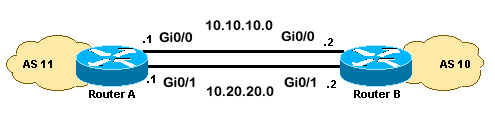
Este cenário mostra como atingir o compartilhamento de carga quando há vários links de mesmo custo (até um máximo de seis). Os links são terminados em um roteador em um sistema autônomo local (AS) e em outro roteador em um AS remoto em um ambiente BGP single-homed. O Diagrama de Rede serve como exemplo.
Diagrama de Rede
Essa seção utiliza esta configuração de rede:
Configurações
Esta seção utiliza as seguintes configurações:
RoteadorA
interface loopback 0
 ip address 192.168.1.1 255.255.255.255

interface GigabitEthernet0/1
 ip address 10.20.20.1 255.255.255.0

interface GigabitEthernet0/0
 ip address 10.10.10.1 255.255.255.0

router bgp 11
 neighbor 192.168.2.2 remote-as 10
 neighbor 192.168.2.2 update-source loopback 0

!--- Use the IP address of the loopback interface for TCP connections.

neighbor 192.168.2.2 ebgp-multihop

!--- You must configure ebgp-multihop whenever the external BGP (eBGP) connections are not on the same network address.

router eigrp 12
 network 192.168.1.1 0.0.0.0
 network 10.0.0.0
 no auto-summary
RoteadorB
interface loopback 0
 ip address 192.168.2.2 255.255.255.255

interface GigabitEthernet0/1
 ip address 10.20.20.2 255.255.255.0

interface GigabitEthernet0/0
 ip address 10.10.10.2 255.255.255.0

router bgp 10
 neighbor 192.168.1.1 remote-as 11
 neighbor 192.168.1.1 update-source loopback 0

!--- Use the IP address of the loopback interface for TCP connections.

neighbor 192.168.1.1 ebgp-multihop

!--- You must configure ebgp-multihop whenever the eBGP connections are not on the same network address.

router eigrp 12
 network 192.168.2.2 0.0.0.0
 network 10.0.0.0
 no auto-summary
Verificar
Use esta seção para confirmar se sua configuração funciona corretamente.
O Cisco CLI Analyzer (somente clientes registrados) aceita alguns comandos show. Use o Cisco CLI Analyzer para visualizar uma análise da saída do comando show.
A saída do comando show ip route mostra ambos os caminhos para a rede 192.168.2.2, aprendidos pelo EIGRP. O comando show ip bgp summary mostra que o vizinho BGP foi construído com o Loopback do roteador remoto. A saída do comando traceroute indica que a carga é distribuída entre dois links seriais. Neste cenário, o compartilhamento de carga ocorre por pacote. Você pode executar o comando ip route-cache nas interfaces seriais para fazer o compartilhamento de carga em uma base por destino. Você também pode configurar o balanceamento de carga por pacote e por destino com o Cisco Express Forwarding. Para obter mais informações sobre como configurar o Cisco Express Forwarding, consulte Configuração do Cisco Express Forwarding.
RouterA#show ip route Codes: L - local, C - connected, S - static, R - RIP, M - mobile, B - BGP D - EIGRP, EX - EIGRP external, O - OSPF, IA - OSPF inter area N1 - OSPF NSSA external type 1, N2 - OSPF NSSA external type 2 E1 - OSPF external type 1, E2 - OSPF external type 2 i - IS-IS, su - IS-IS summary, L1 - IS-IS level-1, L2 - IS-IS level-2 ia - IS-IS inter area, * - candidate default, U - per-user static route o - ODR, P - periodic downloaded static route, H - NHRP, l - LISP a - application route + - replicated route, % - next hop override, p - overrides from PfR Gateway of last resort is not set 10.0.0.0/8 is variably subnetted, 4 subnets, 2 masks C 10.10.10.0/24 is directly connected, GigabitEthernet0/0 L 10.10.10.1/32 is directly connected, GigabitEthernet0/0 C 10.20.20.0/24 is directly connected, GigabitEthernet0/1 L 10.20.20.1/32 is directly connected, GigabitEthernet0/1 192.168.1.0/32 is subnetted, 1 subnets C 192.168.1.1 is directly connected, Loopback0 192.168.2.0/32 is subnetted, 1 subnets D 192.168.2.2 [90/130816] via 10.20.20.2, 00:02:01, GigabitEthernet0/1 [90/130816] via 10.10.10.2, 00:02:01, GigabitEthernet0/0 RouterA#RouterA#show ip bgp summary BGP router identifier 192.168.1.1, local AS number 11 BGP table version is 1, main routing table version 1 Neighbor V AS MsgRcvd MsgSent TblVer InQ OutQ Up/Down State/PfxRcd 192.168.2.2 4 10 20 20 1 0 0 00:15:05 0RouterA#traceroute 192.168.2.2 Type escape sequence to abort. Tracing the route to 192.168.2.2 VRF info: (vrf in name/id, vrf out name/id) 1 10.10.10.2 2 msec 10.20.20.2 2 msec 10.10.10.2 2 msec RouterA#
Troubleshooting
No momento, não há informações específicas disponíveis para solucionar esse problema de configuração.
Compartilhamento de Carga Quando Dual-Homed para um Provedor de Serviços Internet (ISP) através de um único Roteador Local
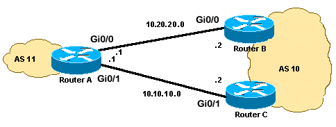
Este cenário mostra como atingir o compartilhamento de carga quando existem vários links entre um AS remoto e um AS local. Esses links são terminados em um roteador no AS local e em vários roteadores em ASs remotos em um ambiente BGP single-homed. O Diagrama de Rede é um exemplo de tal rede.
Esta configuração de exemplo usa o comando maximum-paths. Por padrão, o BGP escolhe um melhor caminho entre os possíveis caminhos de custo igual que são aprendidos de um AS. No entanto, você pode alterar o número máximo de caminhos paralelos de mesmo custo permitidos. Para fazer essa alteração, inclua o comando maximum-paths paths na configuração de BGP. Use um número entre 1 e 6 para o argumento caminhos.
Diagrama de Rede
Essa seção utiliza esta configuração de rede:
Configurações
Esta seção utiliza as seguintes configurações:
RoteadorA
interface Loopback0
 ip address 192.168.1.1 255.255.255.255
!
interface GigabitEthernet0/0
 ip address 10.20.20.1 255.255.255.0
!
!
interface GigabitEthernet0/1
 ip address 10.10.10.1 255.255.255.0
!
!
router bgp 11
 neighbor 10.20.20.2 remote-as 10
 neighbor 10.10.10.2 remote-as 10
 network 192.168.1.1 mask 255.255.255.255
 maximum-paths 2

!--- This command specifies the maximum number of paths to install in the routing table for a specific destination.
RoteadorB
interface GigabitEthernet0/2
 ip address 172.16.2.1 255.255.255.0
!
interface GigabitEthernet0/0
 ip address 10.20.20.2 255.255.255.0
!
!
router bgp 10
 neighbor 10.20.20.1 remote-as 11
 network 172.16.2.0 mask 255.255.255.0
RoteadorC
interface GigabitEthernet0/2
 ip address 172.16.2.2 255.255.255.0
!
interface GigabitEthernet0/1
 ip address 10.10.10.2 255.255.255.0
!
!
router bgp 10
neighbor 10.10.10.1 remote-as 11
network 172.16.2.0 mask 255.255.255.0
Verificar
Use esta seção para confirmar se sua configuração funciona corretamente.
O Cisco CLI Analyzer (somente clientes registrados) aceita alguns comandos show. Use o Cisco CLI Analyzer para visualizar uma análise da saída do comando show.
A saída do comando show ip route mostra que ambos os caminhos para a rede 172.16.2.0 são aprendidos pelo BGP. A saída do comando traceroute indica que a carga é distribuída entre dois links seriais. Neste cenário, o compartilhamento de carga ocorre por destino. O comando show ip bgp fornece as entradas válidas para a rede 172.16.2.0.
RouterA#show ip route Codes: L - local, C - connected, S - static, R - RIP, M - mobile, B - BGP D - EIGRP, EX - EIGRP external, O - OSPF, IA - OSPF inter area N1 - OSPF NSSA external type 1, N2 - OSPF NSSA external type 2 E1 - OSPF external type 1, E2 - OSPF external type 2 i - IS-IS, su - IS-IS summary, L1 - IS-IS level-1, L2 - IS-IS level-2 ia - IS-IS inter area, * - candidate default, U - per-user static route o - ODR, P - periodic downloaded static route, H - NHRP, l - LISP a - application route + - replicated route, % - next hop override, p - overrides from PfR Gateway of last resort is not set 10.0.0.0/8 is variably subnetted, 4 subnets, 2 masks C 10.10.10.0/24 is directly connected, GigabitEthernet0/1 L 10.10.10.1/32 is directly connected, GigabitEthernet0/1 C 10.20.20.0/24 is directly connected, GigabitEthernet0/0 L 10.20.20.1/32 is directly connected, GigabitEthernet0/0 172.16.0.0/24 is subnetted, 1 subnets B 172.16.2.0 [20/0] via 10.20.20.2, 00:08:51 [20/0] via 10.10.10.2, 00:08:51 192.168.1.0/32 is subnetted, 1 subnets C 192.168.1.1 is directly connected, Loopback0RouterA#traceroute 172.16.2.2 source loopback0 Type escape sequence to abort. Tracing the route to 172.16.2.2 VRF info: (vrf in name/id, vrf out name/id) 1 10.10.10.2 3 msec 10.20.20.2 3 msec 10.10.10.2 3 msec RouterA#RouterA#show ip bgp BGP table version is 4, local router ID is 192.168.1.1 Status codes: s suppressed, d damped, h history, * valid, > best, i - internal, r RIB-failure, S Stale, m multipath, b backup-path, f RT-Filter, x best-external, a additional-path, c RIB-compressed, t secondary path, Origin codes: i - IGP, e - EGP, ? - incomplete RPKI validation codes: V valid, I invalid, N Not found Network Next Hop Metric LocPrf Weight Path *m 172.16.2.0/24 10.10.10.2 0 0 10 i *> 10.20.20.2 0 0 10 i *> 192.168.1.1/32 0.0.0.0 0 32768 i
Troubleshooting
No momento, não há informações específicas disponíveis para solucionar esse problema de configuração.
Compartilhamento de carga quando Dual-Homed para um ISP através de vários roteadores locais
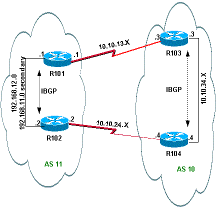
Este cenário mostra como atingir o compartilhamento de carga quando há várias conexões ao mesmo ISP através de vários roteadores locais. Os dois peers eBGP são terminados em dois roteadores locais separados. O balanceamento de carga nos dois enlaces não é possível porque o BGP escolhe o melhor caminho único entre as redes aprendidas do eBGP e do BGP interno (iBGP). O compartilhamento de carga entre os vários caminhos para AS 10 é a melhor opção. Com esse tipo de compartilhamento de carga, o tráfego para redes específicas, com base em políticas predefinidas, trafega por ambos os links. Além disso, cada link atua como um backup para o outro link, caso um link falhe.
Para simplificar, suponha que a política de roteamento BGP para AS 11 seja:
-
O AS 11 aceita as rotas locais do AS 10, juntamente com um padrão para o restante das rotas da Internet.
-
A política de tráfego de saída é:
-
Todo o tráfego destinado à Internet do R101 sai pelo link R101-R103.
-
Se o enlace R101-R103 falhar, todo o tráfego para a Internet vindo de R101 irá para R102 a AS 10.
-
Da mesma forma, todo o tráfego destinado à Internet de R102 passa pelo link R102-R104.
-
Se o enlace R102-R104 falhar, todo o tráfego para a Internet de R102 passará pelo R101 para o AS 10.
-
-
A política de tráfego de entrada é:
-
O tráfego destinado à rede 192.168.11.0/24 da Internet vem do link R103-R101.
-
O tráfego destinado à rede 192.168.12.0/24 da Internet vem do link R104-R102.
-
Se um link para o AS 10 falhar, o outro enlace roteará o tráfego destinado a todas as redes de volta para o AS 11 da Internet.
-
Para conseguir isso, 192.168.11.0 é anunciado de R101 para R103 com um AS_PATH menor do que o anunciado de R102 para R104. O AS 10 encontra o melhor caminho através do link R103-R101. Da mesma forma, 192.168.12.0 é anunciado com um caminho mais curto através do link R102-R104. O AS 10 prefere o link R104-R102 para o tráfego associado a 192.168.12.0 no AS 11.
Para o tráfego de saída, o BGP determina o melhor caminho com base nas rotas aprendidas através do eBGP. Essas rotas são preferíveis às rotas aprendidas através do iBGP. O R101 aprende 10.10.34.0 do R103 através do eBGP e do R102 através do iBGP. O caminho externo é selecionado sobre o caminho interno. Se você observar a tabela BGP na configuração R101, a rota em direção a 10.10.34.0 seria através do link R101-R103, com o próximo salto 10.10.13.3. Em R102, a rota em direção a 10.10.34.0 é através do link R102-R104, com o próximo salto 10.10.24.4. Isso atinge o compartilhamento de carga para o tráfego destinado a 10.10.34.0. Razões semelhantes se aplicam às rotas padrão em R101 e R102. Para obter mais informações sobre os critérios de seleção de caminho BGP, consulte Algoritmo de Seleção de Melhor Caminho BGP.
Diagrama de Rede
Essa seção utiliza esta configuração de rede:
Configurações
Esta seção utiliza as seguintes configurações:
R101
hostname R101
!
interface Ethernet0/0
 ip address 192.168.11.1 255.255.255.0 secondary
 ip address 192.168.12.1 255.255.255.0
!
interface Serial8/0
 ip address 10.10.13.1 255.255.255.0
!
router bgp 11
 no synchronization
 bgp log-neighbor-changes
 network 192.168.11.0
 network 192.168.12.0
 neighbor 10.10.13.3 remote-as 10
 neighbor 10.10.13.3 route-map R101-103-MAP out

!--- The AS_PATH is increased for 192.168.12.0.

 neighbor 192.168.12.2 remote-as 11
 neighbor 192.168.12.2 next-hop-self
 maximum-paths 2
 no auto-summary
!
access-list 1 permit 192.168.12.0
access-list 2 permit 192.168.11.0
route-map R101-103-MAP permit 10
 match ip address 1
 set as-path prepend 11 11 11
!
route-map R101-103-MAP permit 20
 match ip address 2
R102
hostname R102
!
interface Ethernet0/0
 ip address 192.168.11.2 255.255.255.0 secondary
 ip address 192.168.12.2 255.255.255.0
!
interface Serial8/0
 ip address 10.10.24.2 255.255.255.0
!
router bgp 11
 no synchronization
 bgp log-neighbor-changes
 network 192.168.11.0
 network 192.168.12.0
 neighbor 10.10.24.4 remote-as 10
 neighbor 10.10.24.4 route-map R102-104-MAP out

!--- The AS_PATH is increased for 192.168.11.0.

 neighbor 192.168.12.1 remote-as 11
 neighbor 192.168.12.1 next-hop-self
 no auto-summary
!
access-list 1 permit 192.168.11.0
access-list 2 permit 192.168.12.0
route-map R102-104-MAP permit 10
 match ip address 1
 set as-path prepend 11 11 11
!
route-map R102-104-MAP permit 20
 match ip address 2
R103
hostname R103
!
interface Ethernet0/0
 ip address 10.10.34.3 255.255.255.0
!
interface Serial8/0
 ip address 10.10.13.3 255.255.255.0
!
router bgp 10
no synchronization
 bgp log-neighbor-changes
 network 10.10.34.0 mask 255.255.255.0
 neighbor 10.10.13.1 remote-as 11
 neighbor 10.10.13.1 default-originate
 neighbor 10.10.34.4 remote-as 10
 neighbor 10.10.34.4 next-hop-self
 no auto-summary
R104
hostname R104
!
interface Ethernet0/0
 ip address 10.10.34.4 255.255.255.0
!
interface Serial8/0
 ip address 10.10.24.4 255.255.255.0
!
router bgp 10
 no synchronization
 bgp log-neighbor-changes
 neighbor 10.10.24.2 remote-as 11
 neighbor 10.10.24.2 default-originate
 neighbor 10.10.34.3 remote-as 10
 neighbor 10.10.34.3 next-hop-self
 no auto-summary
Verificar
Esta seção fornece informações que você pode usar para confirmar se sua configuração funciona adequadamente.
Determinados comandos show são suportados pelo Cisco CLI Analyzer (somente clientes registrados) , que permite que você veja uma análise da saída do comando show.
Verificação de quando os enlaces entre AS 11 e AS 10 estão ativos
Verificação do Tráfego de Saída
A tabela de BGP em R101 mostra o melhor caminho para todo o tráfego de saída para a Internet é através do link R101-R103. A saída do comando show ip route confirma as rotas na tabela de roteamento.
R101#show ip bgp

BGP table version is 5, local router ID is 192.168.12.1
Status codes: s suppressed, d damped, h history, * valid, > best, i - internal
Origin codes: i - IGP, e - EGP, ? - incomplete

   Network          Next Hop            Metric LocPrf Weight Path
* i0.0.0.0          192.168.12.2                  100      0 10 i
*>                  10.10.13.3                             0 10 i
!--- This is the next hop of R103.

* i10.10.34.0/24    192.168.12.2                  100      0 10 i
*>                  10.10.13.3               0             0 10 i
!--- This is the next hop of R103.
* i192.168.11.0     192.168.12.2             0    100      0 i
*>                  0.0.0.0                  0         32768 i
* i192.168.12.0     192.168.12.2             0    100      0 i
*>                  0.0.0.0                  0         32768 i

R101#show ip route

!--- Output suppressed.

Gateway of last resort is 10.10.13.3 to network 0.0.0.0

C    192.168.12.0/24 is directly connected, Ethernet0/0
C    192.168.11.0/24 is directly connected, Ethernet0/0
     10.0.0.0/24 is subnetted, 2 subnets
C       10.10.13.0 is directly connected, Serial8/0
B       10.10.34.0 [20/0] via 10.10.13.3, 00:08:53
!--- This is the next hop of R103.

B*   0.0.0.0/0 [20/0] via 10.10.13.3, 00:08:53
!--- This is the next hop of R103.
Estas são as tabelas de BGP e roteamento para R102. Com base na política, o R102 roteia todo o tráfego para AS 10 através do link R102-R104:
R102#show ip bgp

BGP table version is 7, local router ID is 192.168.12.2
Status codes: s suppressed, d damped, h history, * valid, > best, i - internal
Origin codes: i - IGP, e - EGP, ? - incomplete

   Network          Next Hop            Metric LocPrf Weight Path
*> 0.0.0.0          10.10.24.4                             0 10 i
!--- This is the next hop of R104.

* i                 192.168.12.1                  100      0 10 i
*> 10.10.34.0/24    10.10.24.4                             0 10 i
!--- This is the next hop of R104.

* i                 192.168.12.1             0    100      0 10 i
* i192.168.11.0     192.168.12.1             0    100      0 i
*>                  0.0.0.0                  0         32768 i
* i192.168.12.0     192.168.12.1             0    100      0 i
*>                  0.0.0.0                  0         32768 i

R102#show ip route

!--- Output suppressed.

Gateway of last resort is 10.10.24.4 to network 0.0.0.0

C    192.168.12.0/24 is directly connected, Ethernet0/0
C    192.168.11.0/24 is directly connected, Ethernet0/0
     10.0.0.0/24 is subnetted, 2 subnets
C       10.10.24.0 is directly connected, Serial8/0
B       10.10.34.0 [20/0] via 10.10.24.4, 00:11:21
!--- This is the next hop of R104.

B*   0.0.0.0/0 [20/0] via 10.10.24.4, 00:11:21
!--- This is the next hop of R104.
Verificação do tráfego de entrada do AS 10 para o AS 11
As redes 192.168.11.0 e 192.168.12.0 pertencem ao AS 11. Com base na política, o AS 11 prefere o link R103-R101 para tráfego destinado à rede 192.168.11.0 e o link R104-R102 para tráfego destinado à rede 192.168.12.0.
R103#show ip bgp

BGP table version is 4, local router ID is 10.10.34.3
Status codes: s suppressed, d damped, h history, * valid, > best, i - internal
Origin codes: i - IGP, e - EGP, ? - incomplete

   Network          Next Hop            Metric LocPrf Weight Path
*> 10.10.34.0/24    0.0.0.0                  0         32768 i
*> 192.168.11.0     10.10.13.1               0             0 11 i
!--- The next hop is R101.
*  192.168.12.0     10.10.13.1               0             0 11 11 11 11 i
*>i                 10.10.34.4               0    100      0 11 i
!--- The next hop is R104.


R103#show ip route

!--- Output suppressed.
Gateway of last resort is not set

B    192.168.12.0/24 [200/0] via 10.10.34.4, 00:04:46
!--- The next hop is R104.

B    192.168.11.0/24 [20/0] via 10.10.13.1, 00:04:46
!--- The next hop is R101.

     10.0.0.0/24 is subnetted, 2 subnets
C       10.10.13.0 is directly connected, Serial8/0
C       10.10.34.0 is directly connected, Ethernet0/0
O melhor caminho para a rede 192.168.11.0 em R103 é através do link R103-R101, e o melhor caminho para a rede 192.168.12.0 é através de R104 para AS 11. Nesse caso, o comprimento do caminho mais curto determina o melhor caminho.
Da mesma forma, em R104, o BGP e a tabela de roteamento se parecem com isto:
R104#show ip bgp

BGP table version is 13, local router ID is 10.10.34.4
Status codes: s suppressed, d damped, h history, * valid, > best, i - internal
Origin codes: i - IGP, e - EGP, ? - incomplete

   Network          Next Hop            Metric LocPrf Weight Path
*>i10.10.34.0/24    10.10.34.3               0    100      0 i
*>i192.168.11.0     10.10.34.3               0    100      0 11 i
*                   10.10.24.2               0             0 11 11 11 11 i
*> 192.168.12.0     10.10.24.2               0             0 11 i

R104#show ip route

!--- Output suppressed.
Gateway of last resort is not set

B    192.168.12.0/24 [20/0] via 10.10.24.2, 00:49:06
!--- The next hop is R102.

B    192.168.11.0/24 [200/0] via 10.10.34.3, 00:07:36
!--- The next hop is R103.

     10.0.0.0/24 is subnetted, 2 subnets
C       10.10.24.0 is directly connected, Serial8/0
C       10.10.34.0 is directly connected, Ethernet0/0
Verificação quando o enlace R101-R103 falha
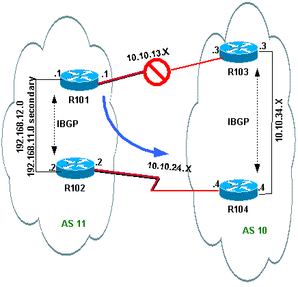
Quando o link R101-R103 falhar, todo o tráfego deverá ser redirecionado por meio do R102. Este diagrama ilustra esta alteração:
Desligue o link R103-R101 em R103 para simular essa situação.
R103(config)#interface serial 8/0
R103(config-if)#shutdown

*May 1 00:52:33.379: %BGP-5-ADJCHANGE: neighbor 10.10.13.1 Down Interface flap
*May 1 00:52:35.311: %LINK-5-CHANGED: Interface Serial8/0, changed state to administratively down
*May 1 00:52:36.127: %LINEPROTO-5-UPDOWN: Line protocol on Interface Serial8/0, changed state to down
Verifique a rota externa para o AS 10.
R101#show ip bgp

BGP table version is 17, local router ID is 192.168.12.1
Status codes: s suppressed, d damped, h history, * valid, > best, i - internal
Origin codes: i - IGP, e - EGP, ? - incomplete

   Network          Next Hop            Metric LocPrf Weight Path
*>i0.0.0.0          192.168.12.2                  100      0 10 i
!--- This is the next hop of R102.
*>i10.10.34.0/24    192.168.12.2                  100      0 10 i
!--- This is the next hop of R102.

* i192.168.11.0     192.168.12.2             0    100      0 i
*>                  0.0.0.0                  0         32768 i
* i192.168.12.0     192.168.12.2             0    100      0 i
*>                  0.0.0.0                  0         32768 i

R101#show ip route

!--- Output suppressed.

Gateway of last resort is 192.168.12.2 to network 0.0.0.0

C    192.168.12.0/24 is directly connected, Ethernet0/0
C    192.168.11.0/24 is directly connected, Ethernet0/0
     10.0.0.0/24 is subnetted, 1 subnets
B       10.10.34.0 [200/0] via 192.168.12.2, 00:01:34
B*   0.0.0.0/0 [200/0] via 192.168.12.2, 00:01:34

!--- All outbound traffic goes through R102.

R102#show ip route

!--- Output suppressed.

Gateway of last resort is 10.10.24.4 to network 0.0.0.0

C    192.168.12.0/24 is directly connected, Ethernet0/0
 C    192.168.11.0/24 is directly connected, Ethernet0/0
     10.0.0.0/24 is subnetted, 2 subnets
C       10.10.24.0 is directly connected, Serial8/0
B       10.10.34.0 [20/0] via 10.10.24.4, 00:13:22
B*   0.0.0.0/0 [20/0] via 10.10.24.4, 00:55:22

!--- All outbound traffic on R102 goes through R104.
Verifique a rota de tráfego de entrada quando R101-R103 estiver inativo.
R103#show ip bgp

BGP table version is 6, local router ID is 10.10.34.3
Status codes: s suppressed, d damped, h history, * valid, > best, i - internal
Origin codes: i - IGP, e - EGP, ? - incomplete

   Network          Next Hop            Metric LocPrf Weight Path
*> 10.10.34.0/24    0.0.0.0                  0         32768 i
*>i192.168.11.0     10.10.34.4               0    100      0 11 11 11 11 i
*>i192.168.12.0     10.10.34.4               0    100      0 11 i

R103#show ip route

!--- Output suppressed.
Gateway of last resort is not set

B    192.168.12.0/24 [200/0] via 10.10.34.4, 00:14:55
!--- The next hop is R104.

B    192.168.11.0/24 [200/0] via 10.10.34.4, 00:05:46
!--- The next hop is R104.
     10.0.0.0/24 is subnetted, 1 subnets
C       10.10.34.0 is directly connected, Ethernet0/0
Em R104, o tráfego para 192.168.11.0 e 192.168.12.0 passa pelo link R104-R102.
R104#show ip route

!--- Output suppressed.

Gateway of last resort is not set

B    192.168.12.0/24 [20/0] via 10.10.24.2, 00:58:35
!--- The next hop is R102.

B    192.168.11.0/24 [20/0] via 10.10.24.2, 00:07:57
!--- The next hop is R102.

     10.0.0.0/24 is subnetted, 2 subnets
C       10.10.24.0 is directly connected, Serial8/0
C       10.10.34.0 is directly connected, Ethernet0/0
Troubleshooting
No momento, não há informações específicas disponíveis para solucionar esse problema de configuração.
Compartilhamento de carga quando multihomed para dois ISPs por um único roteador local
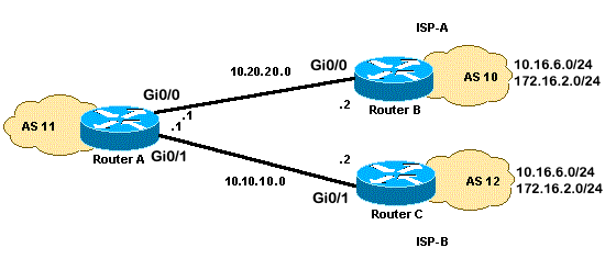
Neste cenário, o balanceamento de carga não é uma opção em um ambiente multihomed, portanto, você só pode fazer o compartilhamento de carga. Você não pode fazer o balanceamento de carga porque o BGP seleciona apenas um único melhor caminho para um destino entre as rotas BGP aprendidas dos ASs diferentes. A ideia é definir uma métrica melhor para as rotas no intervalo de 1.0.0.x a 128.0.0.x que são aprendidas do ISP(A) e uma métrica melhor para o resto das rotas aprendidas do ISP(B). O Diagrama de Rede é um exemplo.
Consulte Configuração de Exemplo para BGP com Dois Provedores de Serviço Diferentes (Multihoming) para obter informações adicionais.
Diagrama de Rede
Essa seção utiliza esta configuração de rede:
Configurações
Esta seção utiliza as seguintes configurações:
RoteadorA
interface GigabitEthernet0/0
 ip address 10.20.20.1 255.255.255.0

interface GigabitEthernet0/1
 ip address 10.10.10.1 255.255.255.0

router bgp 11
 neighbor 10.20.20.2 remote-as 10
 neighbor 10.20.20.2 route-map UPDATES-1 in

!--- This allows only the networks up to 128.0.0.x.

neighbor 10.10.10.2 remote-as 12
neighbor 10.10.10.2 route-map UPDATES-2 in

!--- This allows anything above the 128.0.0.x network.

route-map UPDATES-1 permit 10
 match ip address 1
 set weight 100

route-map UPDATES-1 permit 20
 match ip address 2

route-map UPDATES-2 permit 10
 match ip address 1

route-map UPDATES-2 permit 20
 match ip address 2
 set weight 100

access-list 1 permit 0.0.0.0 127.255.255.255
access-list 2 deny 0.0.0.0 127.255.255.255
access-list 2 permit any
RoteadorB
interface GigabitEthernet0/2
 ip address 172.16.2.1 255.255.255.0

interface GigabitEthernet0/3
 ip address 10.16.6.1 255.255.255.0

interface GigabitEthernet0/0
 ip address 10.20.20.2 255.255.255.0

router bgp 10
 neighbor 10.20.20.1 remote-as 11
 network 172.16.2.0 mask 255.255.255.0
 network 10.16.6.0 mask 255.255.255.0
RoteadorC
interface GigabitEthernet0/3
 ip address 10.16.6.2 255.255.255.0

interface GigabitEthernet0/2
 ip address 172.16.2.2 255.255.255.0

interface GigabitEthernet0/1
 ip address 10.10.10.2 255.255.255.0

router bgp 12
 neighbor 10.10.10.1 remote-as 11
 network 172.16.2.0 mask 255.255.255.0
 network 10.16.6.0 mask 255.255.255.0
Verificar
Use esta seção para confirmar se sua configuração funciona corretamente.
O Cisco CLI Analyzer (somente clientes registrados) aceita alguns comandos show. Use o Cisco CLI Analyzer para visualizar uma análise da saída do comando show.
A saída do comando show ip route e a saída do comando traceroute mostram qualquer rede inferior a 128.0.0.x sai do RouterA por 10.20.20.2. Essa rota é o próximo salto da interface serial 0. O restante das redes sai por 10.10.10.2, que é o próximo salto da interface serial 1.
RouterA#show ip route
!--- Output suppressed.
Gateway of last resort is not set
B 172.16.2.0/24 [20/0] via 10.10.10.2, 00:13:16
!--- This is the next hop out through GigabitEthernet0/0.
B 10.16.6.0/24 [20/0] via 10.20.20.2, 00:13:16 !--- This is the next hop out through GigabitEthernet0/1.
!--- Output suppressed.RouterA#show ip cef 172.16.2.0 172.16.2.0/24 nexthop 10.10.10.2 GigabitEthernet0/1 RouterA#show ip cef 10.16.6.0 10.16.6.0/24 nexthop 10.20.20.2 GigabitEthernet0/0RouterA#show ip bgp BGP table version is 10, local router ID is 192.168.1.1 Status codes: s suppressed, d damped, h history, * valid, > best, i - internal, r RIB-failure, S Stale, m multipath, b backup-path, f RT-Filter, x best-external, a additional-path, c RIB-compressed, t secondary path, Origin codes: i - IGP, e - EGP, ? - incomplete RPKI validation codes: V valid, I invalid, N Not found Network Next Hop Metric LocPrf Weight Path *> 10.16.6.0/24 10.20.20.2 0 100 10 i * 10.10.10.2 0 0 12 i * 172.16.2.0/24 10.20.20.2 0 0 10 i *> 10.10.10.2 0 100 12 i *> 192.168.1.1/32 0.0.0.0 0 32768 iRouterA#traceroute 172.16.2.1 source loopback0 Type escape sequence to abort. Tracing the route to 172.16.2.1 VRF info: (vrf in name/id, vrf out name/id) 1 10.10.10.2 2 msec 3 msec 2 msec 2 172.16.2.1 [AS 12] 3 msec 3 msec * RouterA#traceroute 10.16.6.1 source loopback0 Type escape sequence to abort. Tracing the route to 10.16.6.1 VRF info: (vrf in name/id, vrf out name/id) 1 10.20.20.2 3 msec 2 msec * RouterA#
Troubleshooting
No momento, não há informações específicas disponíveis para solucionar esse problema de configuração.
Compartilhamento de carga quando multihomed para dois ISPs através de vários roteadores locais
O balanceamento de carga não é possível em um ambiente multihomed com dois ISPs. O BGP seleciona apenas o melhor caminho único para um destino entre os caminhos BGP aprendidos de ASs diferentes, o que torna impossível o balanceamento de carga. Mas, o compartilhamento de carga é possível em tais redes BGP multihomed. Com base em políticas predeterminadas, o fluxo de tráfego é controlado com diferentes atributos de BGP.
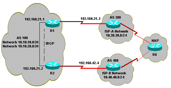
Esta seção discute as configurações multihomed que têm o uso mais frequente. A configuração mostra como atingir o compartilhamento de carga. Veja o Diagrama de Rede, no qual o multihome do AS 100 alcança confiabilidade e compartilhamento de carga.
Para simplificar, suponha que a política de roteamento BGP para AS 100 seja:
-
O AS 100 aceita as rotas locais de ambos os provedores, juntamente com um padrão para as outras rotas de Internet.
-
A política de tráfego de saída é:
-
O tráfego destinado ao AS 300 passa pelo link R1-ISP(A).
-
O tráfego destinado ao AS 400 passa pelo link R2-ISP(B).
-
Todo o tráfego restante prefere a rota padrão 0.0.0.0 através do link R1-ISP(A).
-
Se o link R1-ISP(A) falhar, todo o tráfego passará pelo link R2-ISP(B).
-
-
A política de tráfego de entrada é:
-
O tráfego destinado à rede 10.10.10.0/24 da Internet vem do link ISP(A)-R1.
-
O tráfego destinado à rede 10.10.20.0/24 da Internet vem do link ISP(B)-R2.
-
Se um ISP falhar, o outro roteará o tráfego de volta ao AS 100 da Internet para todas as redes.
-
Diagrama de Rede
Essa seção utiliza esta configuração de rede:
Configurações
Esta seção utiliza as seguintes configurações:
R2
interface Ethernet0
 ip address 192.168.21.2 255.255.255.0
 !
interface Serial0
  ip address 192.168.42.2 255.255.255.0
router bgp 100
 no synchronization
 bgp log-neighbor-changes

!--- The next two lines announce the networks to BGP peers.

 network 10.10.10.0 mask 255.255.255.0
 network 10.10.20.0 mask 255.255.255.0

!--- The next line configures iBGP on R1.

  neighbor 192.168.21.1 remote-as 100
  neighbor 192.168.21.1 next-hop-self

!--- The next line configures eBGP with ISP(B).

 neighbor 192.168.42.4 remote-as 400

!--- This is the incoming policy route map for the application of attributes to specific routes.

 neighbor 192.168.42.4 route-map AS-400-INCOMING in

!--- This is the outgoing policy route map for the application of attributes to specific routes.

 neighbor 192.168.42.4 route-map AS-400-OUTGOING out
 no auto-summary

!--- This line sets the AS path access list, it permits all routes within the routing domain of the provider.

ip as-path access-list 1 permit ^400$

!--- These two lines set the access list.

access-list 10 permit 10.10.10.0 0.0.0.255
access-list 20 permit 10.10.20.0 0.0.0.255

!--- The next three lines configure LOCAL_PREF for routes that match AS path access list 1.

route-map AS-400-INCOMING permit 10
 match as-path 1
 set local-preference 150

!--- Here, the route map prepends AS 100 to BGP updates for networks that are permitted by access list 10.

route-map AS-400-OUTGOING permit 10
 match ip address 10
 set as-path prepend 100

!--- This line announces the network that is permitted by access list 20 without any changes in BGP attributes.

route-map AS-400-OUTGOING permit 20
 match ip address 20
R1
interface Serial0/0
 ip address 192.168.31.1 255.255.255.0
!
interface Ethernet1/0
 ip address 192.168.21.1 255.255.255.0
!
router bgp 100
 no synchronization
 bgp log-neighbor-changes
 network 10.10.10.0 mask 255.255.255.0
 network 10.10.20.0 mask 255.255.255.0

!--- IBGP peering with R2

neighbor 192.168.21.2 remote-as 100
neighbor 192.168.21.2 next-hop-self

!--- This line sets eBGP peering with ISP(A).

neighbor 192.168.31.3 remote-as 300

!--- This is the incoming policy route map for the application of attributes to specific routes.

 neighbor 192.168.31.3 route-map AS-300-INCOMING in

!--- This is the outgoing policy route map for the application of attributes to specific routes.

neighbor 192.168.31.3 route-map AS-300-OUTGOING out
 no auto-summary

!--- This line sets the AS path access list, it permits all routes within the routing domain of the provider.

ip as-path access-list 1 permit ^300$

!--- These two lines set the IP access list.

access-list 10 permit 10.10.20.0 0.0.0.255
access-list 20 permit 10.10.10.0 0.0.0.255

!--- The next three lines configure LOCAL_PREF for routes that match AS path access list 1.

route-map AS-300-INCOMING permit 10
 match as-path 1
 set local-preference 200

!--- Here, the route map prepends AS 100 to BGP updates for networks that are permitted by access list 10.

route-map AS-300-OUTGOING permit 10
 match ip address 10
 set as-path prepend 100

!--- This line announces the network that is permitted by access list 20 without any changes in BGP attributes.

route-map AS-300-OUTGOING permit 20
 match ip address 20
!
Verificar
Use esta seção para confirmar se sua configuração funciona corretamente.
O Cisco CLI Analyzer (somente clientes registrados) aceita alguns comandos show. Use o Cisco CLI Analyzer para visualizar uma análise da saída do comando show.
Execute o comando show ip bgp para verificar se a política de saída/entrada funciona.
R1#show ip bgp

BGP table version is 6, local router ID is 192.168.31.1
Status codes: s suppressed, d damped, h history, * valid, > best, i - internal
Origin codes: i - IGP, e - EGP, ? - incomplete

BGP table version is 6, local router ID is 192.168.31.1
Status codes: s suppressed, d damped, h history, * valid, > best, i - internal
Origin codes: i - IGP, e - EGP, ? - incomplete

Network          Next Hop            Metric LocPrf Weight Path
*> 0.0.0.0          192.168.31.3                  200      0 300 i

!--- This line shows that the default route 0.0.0.0/0 is preferred through AS 300, ISP(A).

* i10.10.10.0/24    192.168.21.2             0    100      0 i
*>                  0.0.0.0                  0         32768 i
* i10.10.20.0/24    192.168.21.2             0    100      0 i
*>                  0.0.0.0                  0         32768 i
*> 10.30.30.0/24    192.168.31.3             0    200      0 300 i
*>i10.40.40.0/24    192.168.21.2             0    150      0 400 i


!--- The route to network 10.30.30.0/24 (AS 300) is preferred through the R1-ISP(A) link.
!--- The route to network 10.40.40.0/24 (AS 400) is preferred through the R2-ISP(B) link.
Agora, observe a saída de show ip bgp em R2:
R2#show ip bgp

BGP table version is 8, local router ID is 192.168.42.2
Status codes: s suppressed, d damped, h history, * valid, > best, i - internal
Origin codes: i - IGP, e - EGP, ? - incomplete

   Network          Next Hop            Metric LocPrf Weight Path
*  0.0.0.0          192.168.42.4                  150      0 400 i
*>i                 192.168.21.1                  200      0 300 i

!--- This line shows that the default route 0.0.0.0/0 is preferred through AS 300, through the R2-ISP(B) link.

*> 10.10.10.0/24    0.0.0.0                  0         32768 i
* i                 192.168.21.1             0    100      0 i
*> 10.10.20.0/24    0.0.0.0                  0         32768 i
* i                 192.168.21.1             0    100      0 i
*>i10.30.30.0/24    192.168.21.1             0    200      0 300 i
*> 10.40.40.0/24    192.168.42.4             0    150      0 400 i

!--- The route to network 10.30.30.0/24 (AS 300) is preferred through the R1-ISP(A) link.
!--- The route to network 10.40.40.0/24 (AS 400) is preferred through the R2-ISP(B) link.
Emita o comando show ip bgp no Roteador 6 para observar a política de entrada para as redes 10.10.10.0/24 e 10.10.20.0/24:
R6#show ip bgp

BGP table version is 15, local router ID is 192.168.64.6
Status codes: s suppressed, d damped, h history, * valid, > best, i - internal
Origin codes: i - IGP, e - EGP, ? - incomplete

   Network          Next Hop            Metric LocPrf Weight Path
*> 10.10.10.0/24    192.168.63.3                           0 300 100 100 i

!--- This line shows that network 10.10.10.0/24 is routed through AS 300
!--- with the ISP(A)-R1 link.

*                   192.168.64.4                           0 400 100 100 100 i
*  10.10.20.0/24    192.168.63.3                           0 300 100 100 i
*>                  192.168.64.4                           0 400 100 i

!--- This line shows that network 10.10.20.0/24 is routed through AS 400
!--- with the ISP(B)-R2 link.

*> 10.30.30.0/24    192.168.63.3             0             0 300 i
*> 10.40.40.0/24    192.168.64.4             0             0 400 i
Desligue o link R1-ISP(A) em R1 e observe a tabela de BGP. Espere que todo o tráfego para a Internet seja roteado pelo link R2-ISP(B):
R1(config)#interface serial 0/0
R1(config-if)#shutdown

*May  2 19:00:47.377: %BGP-5-ADJCHANGE: neighbor 192.168.31.3 Down Interface flap
*May  2 19:00:48.277: %LINK-5-CHANGED: Interface Serial0/0, changed state to
 administratively  down
*May 23 12:00:51.255: %LINEPROTO-5-UPDOWN: Line protocol on Interface Serial0, changed
 state to down

R1#show ip bgp

BGP table version is 12, local router ID is 192.168.31.1
Status codes: s suppressed, d damped, h history, * valid, > best, i - internal
Origin codes: i - IGP, e - EGP, ? - incomplete

   Network          Next Hop            Metric LocPrf Weight Path
*>i0.0.0.0          192.168.21.2                  150      0 400 i

!--- The best default path is now through the R2-ISP(B) link.

* i10.10.10.0/24    192.168.21.2             0    100      0 i
*>                  0.0.0.0                  0         32768 i
* i10.10.20.0/24    192.168.21.2             0    100      0 i
*>                  0.0.0.0                  0         32768 i
*>i10.40.40.0/24    192.168.21.2             0    150      0 400 i

R2#show ip bgp

BGP table version is 14, local router ID is 192.168.42.2
Status codes: s suppressed, d damped, h history, * valid, > best, i - internal
Origin codes: i - IGP, e - EGP, ? - incomplete

   Network          Next Hop            Metric LocPrf Weight Path
*> 0.0.0.0          192.168.42.4                  150      0 400 i

!--- The best default route is now through ISP(B) with a local preference of 150.

* i10.10.10.0/24    192.168.21.1             0    100      0 i
*>                  0.0.0.0                  0         32768 i
* i10.10.20.0/24    192.168.21.1             0    100      0 i
*>                  0.0.0.0                  0         32768 i
*> 10.40.40.0/24    192.168.42.4             0    150      0 400 i
Veja a rota da rede 10.10.10.0/24 no roteador 6:
R6#show ip bgp

BGP table version is 14, local router ID is 192.168.64.6
Status codes: s suppressed, d damped, h history, * valid, > best, i - internal
Origin codes: i - IGP, e - EGP, ? - incomplete

   Network          Next Hop            Metric LocPrf Weight Path
*> 10.10.10.0/24    192.168.64.4                           0 400 100 100 i

!--- Network 10.10.10.0 is reachable through ISP(B), which announced the network with AS path prepend.

*> 10.10.20.0/24    192.168.64.4                           0 400 100 i

*> 10.30.30.0/24    192.168.63.3             0             0 300 i
*> 10.40.40.0/24    192.168.64.4             0             0 400 i
Troubleshooting
No momento, não há informações específicas disponíveis para solucionar esse problema de configuração.
Informações Relacionadas
- BGP Multi-homing: Design e solução de problemas - Vídeo do webcast ao vivo
- BGP Multi-homing: Design e solução de problemas - Perguntas e respostas do webcast ao vivo
- Como funciona o balanceamento de carga
- Configuração de exemplo para o BGP com dois provedores de serviço diferentes (multilocal)
- Como os roteadores BGP usam o Multi-Exit Discriminator para a seleção do melhor caminho
- Página de suporte de tecnologia de roteamento IP
- Suporte Técnico e Documentação - Cisco Systems
Histórico de revisões
| Revisão | Data de publicação | Comentários |
|---|---|---|
5.0 |
28-Jul-2026
|
Recertificação |
4.0 |
26-Feb-2025
|
SEO atualizado. |
3.0 |
30-Aug-2023
|
Título atualizado, informações de fundo, requisitos de estilo e formatação. |
1.0 |
10-Dec-2001
|
Versão inicial |
 Feedback