Configuração de Túnel GRE no Cabo
Índice
Introdução
Este documento contém descrições, configurações e verificações para o Generic Routing Encapsulation (GRE) em um ambiente a cabo. O GRE é um protocolo de tunelamento desenvolvido pela Cisco que encapsula uma ampla variedade de tipos de pacotes de protocolo dentro dos túneis de IP.
Antes de Começar
Convenções
Para obter mais informações sobre convenções de documento, consulte as Convenções de dicas técnicas Cisco.
Pré-requisitos
Não existem requisitos específicos para este documento.
Componentes Utilizados
As informações neste documento são baseadas nas versões de software e hardware abaixo.
-
UBR924 do modem a cabo que executa o Software Release 12.1(5)T4 de Cisco IOS®
Nota: Embora seja possível configurar túneis GRE em outras Plataformas do cable modem Cisco, como no uBR904 usando versões do Cisco IOS diferentes, o suporte oficial para esta característica está no Cisco IOS 12.1(5)T4 para uBR920 e do Cisco IOS 12.1(3) para uBR910.
| Plataforma de cable modem | Versão do Cisco IOS Software |
|---|---|
| uBR920 | 12.1(5)T4 |
| uBR910 | De 12.1(3) e mais atrasado |
Para executar esta configuração, você precisa ter uma conectividade de IP entre dois modems a cabo.
As informações neste documento foram criadas a partir de dispositivos em um ambiente de laboratório específico. Todos os dispositivos utilizados neste documento foram iniciados com uma configuração (padrão) inicial. Se você estiver trabalhando em uma rede ativa, certifique-se de que entende o impacto potencial de qualquer comando antes de utilizá-lo.
Material de Suporte
O Tunelamento fornece uma maneira de encapsular pacotes de um protocolo externo dentro de um protocolo de transporte. O Tunelamento é executado como uma interface virtual para fornecer uma interface simples para a configuração. A interface de túnel não é amarrada ao passageiro específico ou protocolos de transporte, contudo, é uma arquitetura que seja projetada proporcionar os serviços necessários executar todo o esquema padrão do encapsulamento de Point-to-Point. Os túneis são link de ponto a ponto, e você deve configurar um túnel separado para cada link.
O GRE cria uma ligação ponto-a-ponto virtual com os Cisco routers nos pontos remotos em uma inter-rede IP. Conectando sub-redes multiprotocol em um ambiente de backbone de protocolo único, Tunelamento IP que usa o GRE permite a expansão de rede através de um ambiente de backbone de protocolo único. Um cable modem termination system (CMTS) é todo o Data-over-Cable Service Interface Specifications (DOCSIS) - roteador de cabo complacente do final do cabeçalho, tal como o Cisco uBR7246, o uBR7223, ou o uBR7246VXR.
Configurar
Nesta seção, você encontrará informações para configurar os recursos descritos neste documento.
Diagrama de Rede
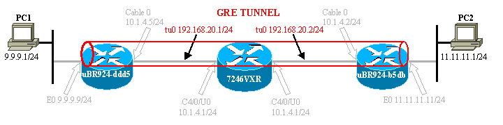
Este documento utiliza a instalação de rede mostrada no diagrama abaixo.
Essa configuração cria um túnel entre os dois modems a cabo uBR924-ddd5 e uBR924-b5db. O exemplo abaixo dos usos dois uBR924s e um uBR7246VXR. Para essa configuração, os nomes dos cable modems são ubr924-ddd5 e ubr924-b5db e usam o Cisco IOS versão 12.1(5)T4. As interfaces de túnel são criadas dinamicamente no modo de configuração global emitindo o comando interface tunnel 0.
Nota: Os modems a cabo uBR900 não precisam estar conectados ao mesmo CMTS uBR7200 ou à rede do mesmo provedor de serviços, desde que haja conectividade IP entre os dois modems a cabo.
Configurações
Este documento utiliza as configurações mostradas abaixo.
Nota: O texto em negrito refere comandos relacionados GRE. Os comentários estão em azul e referem-se à linha acima.
| ubr924-ddd5 |
|---|
version 12.1 no service single-slot-reload-enable no service pad service timestamps debug uptime service timestamps log uptime no service password-encryption ! hostname ubr924-ddd5 ! logging rate-limit console 10 except errors ! clock timezone - -80 ip subnet-zero no ip finger ! call rsvp-sync ! ! ! ! ! ! ! ! ! ! interface Tunnel0 !--- Tunnel interface 0. ip address 192.168.20.1 255.255.255.0 !--- IP address of the GRE tunnel interface 0. tunnel source Ethernet0 !--- IP source of the tunnel. It is best to make this an !--- interface with a public, routable IP address so that !--- it is reachable from the other endpoint of the tunnel. tunnel destination 11.11.11.11 !--- IP destination of the tunnel. Make sure this is !--- reachable via the ping command !--- Otherwise, the tunnel will not be created properly. ! interface Ethernet0 ip address 9.9.9.9 255.255.255.0 ip rip send version 2 !--- Send RIP version 2 packets. ip rip receive version 2 !--- Receive RIP version 2 packets. ! interface cable-modem0 ip rip send version 2 !--- Send RIP version 2 packets. ip rip receive version 2 !--- Receive RIP version 2 packets. cable-modem downstream saved channel 525000000 40 1 cable-modem mac-timer t2 40000 no cable-modem compliant bridge ! router rip version 2 passive-interface Tunnel0 !--- This command is used to avoid recursive routing. network 10.0.0.0 network 9.0.0.0 no auto-summary ! ip default-gateway 10.1.4.1 ip classless no ip http server no ip http cable-monitor ! snmp-server packetsize 4096 snmp-server manager ! voice-port 0 input gain -2 ! voice-port 1 input gain -2 ! ! line con 0 transport input none line vty 0 4 login ! end ubr924-ddd5# |
| ubr924-b5db |
|---|
version 12.1 no service single-slot-reload-enable no service pad service timestamps debug uptime service timestamps log uptime no service password-encryption ! hostname ubr924-b5db ! logging rate-limit console 10 except errors enable password ww ! clock timezone - -80 ip subnet-zero no ip finger ! mgcp call rsvp-sync ! ! ! ! ! ! ! ! ! ! interface Tunnel0 !--- Tunnel interface 0 ip address 192.168.20.2 255.255.255.0 !--- IP address of the gre tunnel interface 0 tunnel source Ethernet0 !--- IP source of the tunnel. It is best to make this an !--- interface with a public, routable IP address so that !--- it is reachable from the other endpoint of the tunnel. tunnel destination 9.9.9.9 !--- IP destination of the tunnel. Make sure this is !--- reachable via the ping command !--- Otherwise, the tunnel will not be created properly. ! interface Ethernet0 ip address 11.11.11.11 255.255.255.0 ip rip send version 2 !--- Send RIP version 2 packets. ip rip receive version 2 !--- Receive RIP version 2 packets. ! no ip route-cache no ip mroute-cache ! interface cable-modem0 ip rip send version 2 !--- Send RIP version 2 packets. ip rip receive version 2 !--- Receive RIP version 2 packets. no ip route-cache no ip mroute-cache no cable-modem compliant bridge ! router rip version 2 passive-interface Tunnel0 !--- This command is used to avoid recursive routing. network 10.0.0.0 network 11.0.0.0 no auto-summary ! ip default-gateway 10.1.4.1 ip classless no ip http server no ip http cable-monitor ! snmp-server packetsize 4096 snmp-server manager ! voice-port 0 input gain -2 ! voice-port 1 input gain -2 ! ! line con 0 exec-timeout 0 0 transport input none line vty 0 4 password ww login ! end ubr924-b5db# |
Verificar
Esta seção fornece informações que você pode usar para confirmar se sua configuração está funcionando adequadamente.
Determinados comandos show são suportados pela Ferramenta Output Interpreter, que permite que você veja uma análise do resultado do comando show.
Verifique que a configuração CMTS (7246VXR) está correta, e que o Modems a cabo é em linha. A configuração do CMTS é mostrada abaixo.
7246VXR#show run
Building configuration...

Current configuration : 4579 bytes
!
! Last configuration change at 13:22:17 PDT Mon Feb 26 2001
! NVRAM config last updated at 13:22:46 PDT Mon Feb 26 2001
!
version 12.1
no service single-slot-reload-enable
no service pad
service timestamps debug datetime msec localtime
service timestamps log datetime localtime
no service password-encryption
service linenumber
service udp-small-servers max-servers no-limit
!
hostname 7246VXR
!
logging buffered 1000000 debugging
logging rate-limit console 10 except errors
enable password cable
!
cable qos profile 8
cable qos profile 10
cable qos profile 10 grant-size 1500
cable qos profile 12 guaranteed-upstream 100000
no cable qos permission create
no cable qos permission update
cable qos permission modems
cable time-server
clock timezone PDT -8
clock summer-time PDT recurring
clock calendar-valid
ip subnet-zero
no ip finger
!
interface Ethernet2/0
 ip address 172.16.30.4 255.255.255.192
 no ip mroute-cache
 half-duplex
!

interface Cable4/0
 ip address 172.16.29.1 255.255.255.224 secondary
 ip address 10.1.4.1 255.255.255.0
 no keepalive
 cable downstream rate-limit token-bucket shaping
 cable downstream annex B
 cable downstream modulation 64qam
 cable downstream interleave-depth 32
 cable downstream frequency 555000000
 cable upstream 0 frequency 40000000
 cable upstream 0 power-level 0
 no cable upstream 0 shutdown
 cable upstream 1 shutdown
 cable upstream 2 shutdown
 cable upstream 3 shutdown
 cable upstream 4 shutdown
 cable upstream 5 shutdown
 cable dhcp-giaddr policy
 cable helper-address 172.16.30.2
!
interface Cable5/0
 ip address 172.16.29.225 255.255.255.224 secondary
 ip address 10.1.5.1 255.255.255.0
 load-interval 30
 no keepalive
 cable downstream rate-limit token-bucket shaping
 cable downstream annex B
 cable downstream modulation 64qam
 cable downstream interleave-depth 32
 cable downstream frequency 620000000
 cable upstream 0 frequency 25008000
 cable upstream 0 power-level 0
 no cable upstream 0 shutdown
 no cable upstream 1 shutdown
 cable dhcp-giaddr policy
!
router eigrp 202
 redistribute connected
 redistribute static
 network 10.0.0.0
 network 172.16.0.0
 no auto-summary
 no eigrp log-neighbor-changes
!
router rip
 version 2
 redistribute connected
 redistribute static
 network 10.0.0.0
 network 172.16.0.0
 no auto-summary
!
ip default-gateway 172.16.30.1
ip classless
ip route 0.0.0.0 0.0.0.0 172.16.30.1
ip route 172.16.30.0 255.255.255.0 Ethernet2/0
ip http server
ip http authentication local
!
access-list 188 permit tcp any any eq www log
access-list 188 permit ip any any
route-map docsis permit 10
!
snmp-server engineID local 00000009020000E01ED77E40
snmp-server community public RO
snmp-server community private RW

line con 0
 exec-timeout 0 0
 transport input none
line aux 0
 speed 19200
line vty 0 4
 session-timeout 60
 exec-timeout 0 0
!
ntp clock-period 17179973
end

7246VXR#show cable modem
Interface   Prim Online     Timing Rec    QoS CPE IP address      MAC address
            Sid  State      Offset Power
Cable4/0/U0 69   online     2812    0.25  5   0   10.1.4.3        0002.1685.b5db
Cable4/0/U0 70   online     2288    0.00  5   0   10.1.4.6        0010.7bed.9b23
Cable4/0/U0 71   online     2289    0.50  5   0   10.1.4.2        0010.7bed.9b45
Cable4/0/U0 72   online     2812    0.00  5   0   10.1.4.4        0002.fdfa.0a63
Cable4/0/U0 73   online     2812   -0.75  5   0   10.1.4.5        0004.2752.ddd5
Cable4/0/U0 74   online     2813    0.25  5   0   10.1.4.7        0001.64ff.e47d
Se o estado on-line do Modems a cabo não mostra em linha, refira o documento Troubleshooting UBR Cable Modems Not Coming Online.
7246VXR#show ip interface brief
Interface                  IP-Address      OK? Method Status                Protocol
FastEthernet0/0            192.168.7.253   YES NVRAM  up                    down
Ethernet2/0                172.16.30.4     YES manual up                    up
Ethernet2/1                unassigned      YES NVRAM  administratively down down
Ethernet2/2                unassigned      YES NVRAM  administratively down down
Ethernet2/3                unassigned      YES NVRAM  administratively down down
Cable3/0                   10.1.3.1        YES manual up                    up
Cable4/0                   10.1.4.1        YES manual up                    up
Cable5/0                   10.1.5.1        YES manual up                    up

7246VXR#show ip route
Codes: C - connected, S - static, I - IGRP, R - RIP, M - mobile, B - BGP
       D - EIGRP, EX - EIGRP external, O - OSPF, IA - OSPF inter area
       N1 - OSPF NSSA external type 1, N2 - OSPF NSSA external type 2
       E1 - OSPF external type 1, E2 - OSPF external type 2, E - EGP
       i - IS-IS, L1 - IS-IS level-1, L2 - IS-IS level-2, ia - IS-IS inter area
       * - candidate default, U - per-user static route, o - ODR
       P - periodic downloaded static route

Gateway of last resort is 172.16.30.1 to network 0.0.0.0

     172.16.0.0/16 is variably subnetted, 4 subnets, 3 masks
C       172.16.29.224/27 is directly connected, Cable5/0
C       172.16.29.0/27 is directly connected, Cable4/0
S       172.16.30.0/24 is directly connected, Ethernet2/0
C       172.16.30.0/26 is directly connected, Ethernet2/0
     9.0.0.0/24 is subnetted, 1 subnets
R       9.9.9.0 [120/1] via 10.1.4.5, 00:00:09, Cable4/0
R    192.168.20.0/24 [120/1] via 10.1.4.5, 00:00:09, Cable4/0
     10.0.0.0/8 is variably subnetted, 5 subnets, 2 masks
C       10.1.3.0/24 is directly connected, Cable3/0
R       10.5.5.0/24 [120/1] via 10.1.4.4, 00:00:01, Cable4/0
R       10.0.0.0/8 [120/1] via 172.16.30.10, 00:00:24, Ethernet2/0
C       10.1.5.0/24 is directly connected, Cable5/0
C       10.1.4.0/24 is directly connected, Cable4/0
     11.0.0.0/24 is subnetted, 1 subnets
R       11.11.11.0 [120/1] via 10.1.4.3, 00:00:15, Cable4/0
S*   0.0.0.0/0 is directly connected
No lado dos modems a cabo, verifique a versão sh dos dois dispositivos, conforme mostrado a seguir.
ubr924-ddd5#sh ver
Cisco Internetwork Operating System Software
IOS (tm) 920 Software (UBR920-K1V4Y556I-M), Version 12.1(5)T4,  RELEASE SOFTWARE (fc1)
TAC Support: http://www.cisco.com/pcgi-bin/ibld/view.pl?i=support
Copyright (c) 1986-2001 by cisco Systems, Inc.
Compiled Fri 02-Feb-01 10:55 by ccai
Image text-base: 0x800100A0, data-base: 0x806DB770

ROM: System Bootstrap, Version 12.0(6r)T3, RELEASE SOFTWARE (fc1)
ROM: 920 Software (UBR920-K1V4Y556I-M), Version 12.1(5)T4,  RELEASE SOFTWARE (fc1)

ubr924-ddd5 uptime is 2 hours, 1 minute
System returned to ROM by reload at 12:45:25 - Fri Feb 23 2001
System restarted at 12:46:07 - Fri Feb 23 2001
System image file is "flash:ubr920-k1v4y556i-mz.121-5.T4"

cisco uBR920 CM (MPC850) processor (revision 4.d) with 15872K/1024K bytes of memory.
Processor board ID FAA0444Q14Z
Bridging software.
1 Ethernet/IEEE 802.3 interface(s)
1 Cable Modem network interface(s)
3968K bytes of processor board System flash (Read/Write)
1536K bytes of processor board Boot flash (Read/Write)

Configuration register is 0x2102

ubr924-b5db#show ver
Cisco Internetwork Operating System Software
IOS (tm) 920 Software (UBR920-K1V4Y556I-M), Version 12.1(5)T4,  RELEASE SOFTWARE (fc1)
TAC Support: http://www.cisco.com/pcgi-bin/ibld/view.pl?i=support
Copyright (c) 1986-2001 by cisco Systems, Inc.
Compiled Fri 02-Feb-01 10:55 by ccai
Image text-base: 0x800100A0, data-base: 0x806DB770

ROM: System Bootstrap, Version 12.0(6r)T3, RELEASE SOFTWARE (fc1)
ROM: 920 Software (UBR920-K1V4Y556I-M), Version 12.1(5)T4,  RELEASE SOFTWARE (fc1)

ubr924-b5db uptime is 1 hour, 53 minutes
System returned to ROM by reload at 12:55:34 - Fri Feb 23 2001
System restarted at 12:56:15 - Fri Feb 23 2001
System image file is "flash:ubr920-k1v4y556i-mz.121-5.T4"

cisco uBR920 CM (MPC850) processor (revision 3.e) with 15872K/1024K bytes of memory.
Processor board ID FAA0422Q04F
Bridging software.
1 Ethernet/IEEE 802.3 interface(s)
1 Cable Modem network interface(s)
3968K bytes of processor board System flash (Read/Write)
1536K bytes of processor board Boot flash (Read/Write)

Configuration register is 0x2102
O túnel mostrará up/up, desde que existam as seguintes condições:
-
Está configurado com endereços IP válidos.
-
Existe uma rota na tabela de roteamento para o IP Address de destino do túnel, e não o IP Address atribuído para a extremidade oposta do túnel.
Isto deve ser verdadeiro apesar de se você pode sibilar o endereço de destino. Uma rota estática incorreta ou uma indicação de rota padrão na direção errada criará o túnel, que, todavia, não funcionará.
O primeiro passo para verificar o funcionamento do túnel é verificar se ele está ativo. Emita os comandos show ip interface brief e show interface tunnel 0 em ambos os modems a cabo. A saída de exemplo de comando está mostrada abaixo.
ubr924-ddd5#show ip interface brief
Interface                  IP-Address      OK? Method Status                Protocol
Ethernet0                  9.9.9.9         YES manual up                    up
Tunnel0                    192.168.20.1    YES manual up                    up
cable-modem0               10.1.4.5        YES unset  up                    up

ubr924-ddd5#show interface tunnel 0
Tunnel0 is up, line protocol is up
  Hardware is Tunnel
  Internet address is 192.168.20.1/24
  MTU 1514 bytes, BW 9 Kbit, DLY 500000 usec,
     reliability 255/255, txload 1/255, rxload 1/255
  Encapsulation TUNNEL, loopback not set
  Keepalive set (10 sec)
  Tunnel source 9.9.9.9 (Ethernet0), destination 11.11.11.11
  Tunnel protocol/transport GRE/IP, key disabled, sequencing disabled
  Checksumming of packets disabled
  Last input 00:15:25, output 00:14:27, output hang never
  Last clearing of "show interface" counters never
  Queueing strategy: fifo
  Output queue 0/0, 2 drops; input queue 0/75, 0 drops
  5 minute input rate 0 bits/sec, 0 packets/sec
  5 minute output rate 0 bits/sec, 0 packets/sec
     146 packets input, 21024 bytes, 0 no buffer
     Received 0 broadcasts, 0 runts, 0 giants, 0 throttles
     0 input errors, 0 CRC, 0 frame, 0 overrun, 0 ignored, 0 abort
     172 packets output, 57392 bytes, 0 underruns
     0 output errors, 0 collisions, 0 interface resets
     0 output buffer failures, 0 output buffers swapped out


ubr924-b5db#show ip interface brief
Interface                  IP-Address      OK? Method Status                Protocol
Ethernet0                  11.11.11.11     YES manual up                    up
Tunnel0                    192.168.20.2    YES manual up                    up
cable-modem0               10.1.4.3        YES NVRAM  up                    up

ubr924-b5db#show interface tunnel 0
Tunnel0 is up, line protocol is up
  Hardware is Tunnel
  Internet address is 192.168.20.2/24
  MTU 1514 bytes, BW 9 Kbit, DLY 500000 usec,
     reliability 255/255, txload 1/255, rxload 1/255
  Encapsulation TUNNEL, loopback not set
  Keepalive set (10 sec)
  Tunnel source 11.11.11.11 (Ethernet0), destination 9.9.9.9
  Tunnel protocol/transport GRE/IP, key disabled, sequencing disabled
  Checksumming of packets disabled
  Last input 00:16:42, output 00:17:40, output hang never
  Last clearing of "show interface" counters never
  Queueing strategy: fifo
  Output queue 0/0, 5 drops; input queue 0/75, 0 drops
  5 minute input rate 0 bits/sec, 0 packets/sec
  5 minute output rate 0 bits/sec, 0 packets/sec
     118 packets input, 19144 bytes, 0 no buffer
     Received 0 broadcasts, 0 runts, 0 giants, 0 throttles
     0 input errors, 0 CRC, 0 frame, 0 overrun, 0 ignored, 0 abort
     164 packets output, 49624 bytes, 0 underruns
     0 output errors, 0 collisions, 0 interface resets
     0 output buffer failures, 0 output buffers swapped out
Verifique se o trabalho do túnel é efetuar ping no endereço IP de destino do túnel. Dessa forma você irá verificar somente a conectividade de IP, e não o funcionamento real do túnel.
From ubr924-ddd5 we ping 11.11.11.11
ubr924-ddd5#ping 11.11.11.11

Type escape sequence to abort.
Sending 5, 100-byte ICMP Echos to 11.11.11.11, timeout is 2 seconds:
!!!!!
Success rate is 100 percent (5/5), round-trip min/avg/max = 12/14/17 ms
ubr924-ddd5#
Faça o ping de ubr924-b5db do endereço de destino 9.9.9.9.
ubr924-b5db#ping 9.9.9.9

Type escape sequence to abort.
Sending 5, 100-byte ICMP Echos to 9.9.9.9, timeout is 2 seconds:
!!!!!
Success rate is 100 percent (5/5), round-trip min/avg/max = 12/14/16 ms
ubr924-b5db#
Para verificar se o túnel funciona, emita o comando show ip route x.x.x.x, onde x.x.x.x é o endereço IP atribuído à extremidade oposta do túnel. Nesse caso, seria o endereço de loopback do roteador distante. Se a única rota mostrada for para a interface do túnel, executar um ping para tal endereço provará que o túnel funciona.
Se há um esquema de endereçamento de IP que anunciasse rotas à parte traseira do segmento do túnel através da rede, haveria mais de uma rota à ponta oposta da interface de túnel. Se esse for o caso, será muito difícil verificar se o túnel está funcionando. Geralmente nessa situação, você não desejará duplicar as rotas para a rede de tunel. Medidas devem ser tomadas para impedir o anúncio dos roteadores por um Routing Protocol pela rede. Se o túnel está sendo usado para transportar o tráfego de um protocolo diferente do IP, o mesmo método da verificação básica aplica-se.
From ubr924-ddd5 we get
ubr924-ddd5#show ip route 192.168.20.2
Routing entry for 192.168.20.0/24
  Known via "connected", distance 0, metric 0 (connected, via interface)
  Routing Descriptor Blocks:
  * directly connected, via Tunnel0
      Route metric is 0, traffic share count is 1

From ubr924-b5db we get
ubr924-b5db#show ip route 192.168.20.1
Routing entry for 192.168.20.0/24
  Known via "connected", distance 0, metric 0 (connected, via interface)
  Routing Descriptor Blocks:
  * directly connected, via Tunnel0
      Route metric is 0, traffic share count is 1
Para verificar se o PC1 pode acessar o PC2 e vice-versa, realize pings estendidos nos modems a cabo e também pings dos PCs.
Execute um ping estendido em ubr924-b5db de sua interface Ethernet (11.11.11.11) à interface Ethernet ubr924-ddd5 (9.9.9.9).
ubr924-b5db#ping ip
Target IP address: 9.9.9.9

!--- ubr924-ddd5 Ethernet's IP address.

Repeat count [5]:
Datagram size [100]:
Timeout in seconds [2]:
Extended commands [n]: y
Source address or interface: 11.11.11.11

!--- ubr924-b5db Ethernet's IP address.

Type of service [0]:
Set DF bit in IP header? [no]:
Validate reply data? [no]:
Data pattern [0xABCD]:
Loose, Strict, Record, Timestamp, Verbose[none]:
Sweep range of sizes [n]:
Type escape sequence to abort.
Sending 5, 100-byte ICMP Echos to 9.9.9.9, timeout is 2 seconds:
!!!!!
Success rate is 100 percent (5/5), round-trip min/avg/max = 12/16/28 ms
ubr924-b5db#
Execute o oposto para testar a conectividade do outro lado.
ubr924-ddd5#ping ip
Target IP address: 11.11.11.11

!--- ubr924-b5db Ethernet's IP address.

Repeat count [5]:
Datagram size [100]:
Timeout in seconds [2]:
Extended commands [n]: y
Source address or interface: 9.9.9.9

!--- ubr924-ddd5 Ethernet's IP address.

Type of service [0]:
Set DF bit in IP header? [no]:
Validate reply data? [no]:
Data pattern [0xABCD]:
Loose, Strict, Record, Timestamp, Verbose[none]:
Sweep range of sizes [n]:
Type escape sequence to abort.
Sending 5, 100-byte ICMP Echos to 11.11.11.11, timeout is 2 seconds:
!!!!!
Success rate is 100 percent (5/5), round-trip min/avg/max = 12/14/16 ms
ubr924-ddd5#
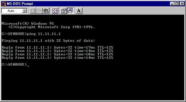
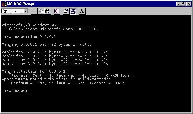
O teste final é emitir um ping de PC1 a PC2, e de PC2 a PC1.
O PC1 possui um endereço IP 9.9.9.1.

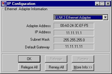
O PC2 tem endereço IP 11.11.11.1.
Ping de PC1 para PC2.
Ping de PC2 para PC1.
Troubleshooting
Atualmente, não existem informações disponíveis específicas sobre Troubleshooting para esta configuração.
Informações Relacionadas
 Feedback
Contate a Cisco
- Abrir um caso de suporte

- (É necessário um Contrato de Serviço da Cisco)