PIX/ASA(버전 7.x 이상) IPsec VPN Tunnel with Network Address Translation 컨피그레이션 예
목차
소개
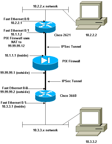
이 샘플 컨피그레이션에서는 NAT(Network Address Translation)를 수행하는 방화벽을 통한 IPsec VPN 터널을 보여 줍니다. 12.2(13)T 이전 버전의 Cisco IOS® Software Releases를 사용하는 경우 이 컨피그레이션은 PAT(Port Address Translation)와 함께 작동하지 않습니다. 이 컨피그레이션 유형은 IP 트래픽을 터널링하는 데 사용할 수 있습니다. 이 컨피그레이션은 IPX 또는 라우팅 업데이트와 같은 방화벽을 통과하지 않는 트래픽을 암호화하는 데 사용할 수 없습니다. GRE(Generic Routing Encapsulation) 터널링이 더 적합한 옵션입니다. 이 예에서 Cisco 2621 및 3660 라우터는 IPsec 트래픽을 허용하기 위해 PIX의 사이에 도관 또는 ACL(Access Control List)이 있는 두 개의 프라이빗 네트워크를 연결하는 IPsec 터널 엔드포인트입니다.
참고: NAT는 일대일 주소 변환이며, 방화벽 내의 다-대-일 변환인 PAT와 혼동되지 않습니다. NAT 작업 및 컨피그레이션에 대한 자세한 내용은 NAT 작업 확인 및 기본 NAT 트러블슈팅 또는 NAT 작동 방식을 참조하십시오.
참고: 외부 터널 엔드포인트 장치가 하나의 IP 주소에서 여러 터널을 처리할 수 없으므로 IPsec with PAT가 제대로 작동하지 않을 수 있습니다. 터널 엔드포인트 디바이스가 PAT와 작동하는지 확인하려면 공급업체에 문의하십시오. 또한 Cisco IOS Software Release 12.2(13)T 이상에서는 NAT 투명성 기능을 PAT에 사용할 수 있습니다. 자세한 내용은 IPSec NAT 투명성을 참조하십시오. Cisco IOS Software Release 12.2(13)T 이상에서 이러한 기능에 대한 자세한 내용은 IPSec ESP Through NAT 지원을 참조하십시오.
참고: Cisco 기술 지원에서 케이스를 열기 전에 NAT FAQ(자주 묻는 질문)를 참조하십시오. NAT는 일반적인 질문에 대한 답변이 많습니다.
PIX 버전 6.x 이전 버전의 NAT가 있는 방화벽을 통한 IPsec 터널을 구성하는 방법에 대한 자세한 내용은 NAT가 있는 방화벽을 통한 IPSec 터널 구성을 참조하십시오.
사전 요구 사항
요구 사항
이 문서에 대한 특정 요건이 없습니다.
사용되는 구성 요소
이 문서의 정보는 다음 소프트웨어 및 하드웨어 버전을 기반으로 합니다.
-
Cisco IOS Software 릴리스 12.0.7.T(Cisco IOS Software 릴리스 12.2(13)T까지(최대 제외)
최신 버전에 대해서는 IPSec NAT 투명성을 참조하십시오.
-
Cisco 2621 라우터
-
Cisco 3660 라우터
-
7.x 이상을 실행하는 Cisco PIX 500 Series Security Appliance
이 문서의 정보는 특정 랩 환경의 디바이스를 토대로 작성되었습니다. 이 문서에 사용된 모든 디바이스는 초기화된(기본) 컨피그레이션으로 시작되었습니다. 현재 네트워크가 작동 중인 경우, 모든 명령어의 잠재적인 영향을 미리 숙지하시기 바랍니다.
표기 규칙
문서 규칙에 대한 자세한 내용은 Cisco 기술 팁 표기 규칙을 참조하십시오.
관련 제품
이 문서는 소프트웨어 버전 7.x 이상이 포함된 Cisco 5500 Series ASA(Adaptive Security Appliance)에서도 사용할 수 있습니다.
구성
이 섹션에서는 이 문서에서 설명하는 기능을 구성하는 데 사용할 수 있는 정보를 제공합니다.
참고: 이 문서에서 사용하는 명령에 대한 추가 정보를 찾으려면 Command Lookup Tool(등록된 고객만 해당)을 사용하십시오.
네트워크 다이어그램
이 문서에서는 이 네트워크 설정을 사용합니다.
설정
이 문서에서는 다음 설정을 사용합니다.
| Cisco 2621 |
|---|
Current configuration: ! version 12.0 service timestamps debug uptime service timestamps log uptime no service password-encryption ! hostname goss-2621 ! ip subnet-zero ! ip audit notify log ip audit po max-events 100 isdn voice-call-failure 0 cns event-service server ! !--- The IKE policy. crypto isakmp policy 10 hash md5 authentication pre-share crypto isakmp key cisco123 address 99.99.99.2 ! crypto ipsec transform-set myset esp-des esp-md5-hmac ! crypto map mymap local-address FastEthernet0/1 !--- IPsec policy. crypto map mymap 10 ipsec-isakmp set peer 99.99.99.2 set transform-set myset !--- Include the private-network-to-private-network traffic !--- in the encryption process. match address 101 ! controller T1 1/0 ! interface FastEthernet0/0 ip address 10.2.2.1 255.255.255.0 no ip directed-broadcast duplex auto speed auto ! interface FastEthernet0/1 ip address 10.1.1.2 255.255.255.0 no ip directed-broadcast duplex auto speed auto !--- Apply to the interface. crypto map mymap ! ip classless ip route 0.0.0.0 0.0.0.0 10.1.1.1 no ip http server !--- Include the private-network-to-private-network traffic !--- in the encryption process. access-list 101 permit ip 10.2.2.0 0.0.0.255 10.3.3.0 0.0.0.255 line con 0 transport input none line aux 0 line vty 0 4 ! no scheduler allocate end |
| Cisco 3660 |
|---|
version 12.0 service timestamps debug uptime service timestamps log uptime no service password-encryption ! hostname goss-3660 ! ip subnet-zero ! cns event-service server ! !--- The IKE policy. crypto isakmp policy 10 hash md5 authentication pre-share crypto isakmp key cisco123 address 99.99.99.12 ! crypto ipsec transform-set myset esp-des esp-md5-hmac ! crypto map mymap local-address FastEthernet0/0 !--- The IPsec policy. crypto map mymap 10 ipsec-isakmp set peer 99.99.99.12 set transform-set myset !--- Include the private-network-to-private-network traffic !--- in the encryption process. match address 101 ! interface FastEthernet0/0 ip address 99.99.99.2 255.255.255.0 no ip directed-broadcast ip nat outside duplex auto speed auto !--- Apply to the interface. crypto map mymap ! interface FastEthernet0/1 ip address 10.3.3.1 255.255.255.0 no ip directed-broadcast ip nat inside duplex auto speed auto ! interface Ethernet3/0 no ip address no ip directed-broadcast shutdown ! interface Serial3/0 no ip address no ip directed-broadcast no ip mroute-cache shutdown ! interface Ethernet3/1 no ip address no ip directed-broadcast interface Ethernet4/0 no ip address no ip directed-broadcast shutdown ! interface TokenRing4/0 no ip address no ip directed-broadcast shutdown ring-speed 16 ! !--- The pool from which inside hosts translate to !--- the globally unique 99.99.99.0/24 network. ip nat pool OUTSIDE 99.99.99.70 99.99.99.80 netmask 255.255.255.0 !--- Except the private network from the NAT process. ip nat inside source route-map nonat pool OUTSIDE ip classless ip route 0.0.0.0 0.0.0.0 99.99.99.1 no ip http server ! !--- Include the private-network-to-private-network traffic !--- in the encryption process. access-list 101 permit ip 10.3.3.0 0.0.0.255 10.2.2.0 0.0.0.255 access-list 101 deny ip 10.3.3.0 0.0.0.255 any !--- Except the private network from the NAT process. access-list 110 deny ip 10.3.3.0 0.0.0.255 10.2.2.0 0.0.0.255 access-list 110 permit ip 10.3.3.0 0.0.0.255 any route-map nonat permit 10 match ip address 110 ! line con 0 transport input none line aux 0 line vty 0 4 ! end |
PIX 보안 어플라이언스 및 액세스 목록 컨피그레이션
ASDM 5.0 컨피그레이션
ASDM을 사용하여 PIX 방화벽 버전 7.0을 구성하려면 다음 단계를 완료합니다.
-
PIX에 대한 콘솔. 지워진 컨피그레이션에서 대화형 프롬프트를 사용하여 워크스테이션 10.1.1.3에서 PIX를 관리하기 위한 ASDM(Advanced Security Device Manager GUI)을 활성화합니다.
PIX 방화벽 ASDM 부트스트랩 Pre-configure Firewall now through interactive prompts [yes]? yes Firewall Mode [Routed]: Enable password [<use current password>]: cisco Allow password recovery [yes]? Clock (UTC): Year [2005]: Month [Mar]: Day [15]: Time [05:40:35]: 14:45:00 Inside IP address: 10.1.1.1 Inside network mask: 255.255.255.0 Host name: pix-firewall Domain name: cisco.com IP address of host running Device Manager: 10.1.1.3 The following configuration will be used: Enable password: cisco Allow password recovery: yes Clock (UTC): 14:45:00 Mar 15 2005 Firewall Mode: Routed Inside IP address: 10.1.1.1 Inside network mask: 255.255.255.0 Host name: OZ-PIX Domain name: cisco.com IP address of host running Device Manager: 10.1.1.3 Use this configuration and write to flash? yes INFO: Security level for "inside" set to 100 by default. Cryptochecksum: a0bff9bb aa3d815f c9fd269a 3f67fef5 965 bytes copied in 0.880 secs -
Workstation 10.1.1.3에서 웹 브라우저를 열고 ADSM(이 예에서는 https://10.1.1.1)을 사용합니다.
-
인증서 프롬프트에서 Yes를 선택하고 PIX 방화벽 ASDM 부트스트랩 컨피그레이션에 구성된 대로 enable 비밀번호를 사용하여 로그인합니다.
-
ASDM이 PC에서 처음 실행되는 경우 ASDM Launcher를 사용할지, 아니면 ASDM을 Java 앱으로 사용할지 묻는 메시지가 표시됩니다.
이 예에서는 ASDM Launcher(ASDM Launcher)를 선택하고 이러한 프롬프트를 설치합니다.
-
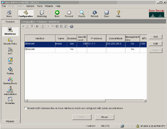
ASDM Home(ASDM 홈) 창으로 이동하여 Configuration(컨피그레이션) 탭을 선택합니다.
-
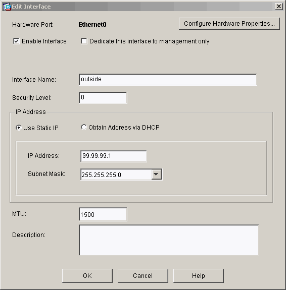
Ethernet 0 Interface(이더넷 0 인터페이스)를 강조 표시하고 Edit(편집)를 클릭하여 Outside Interface(외부 인터페이스)를 구성합니다.
-
Editing interface 프롬프트에서 OK를 클릭합니다.
-
인터페이스 세부사항을 입력하고 완료되면 OK(확인)를 클릭합니다.
-
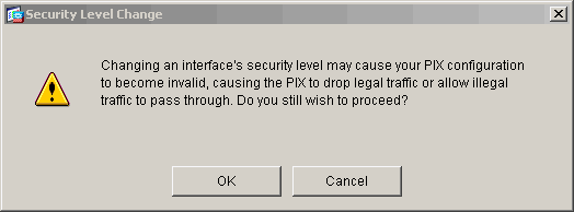
Changing an Interface(인터페이스 변경) 프롬프트에서 OK(확인)를 클릭합니다.
-
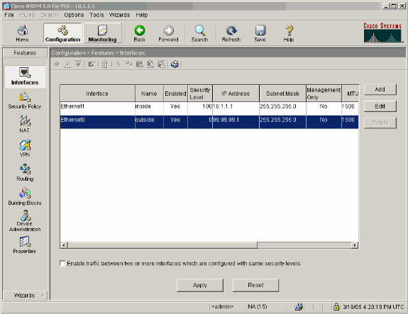
인터페이스 컨피그레이션을 수락하려면 Apply를 클릭합니다. 컨피그레이션도 PIX에 푸시됩니다. 이 예에서는 고정 경로를 사용합니다.
-
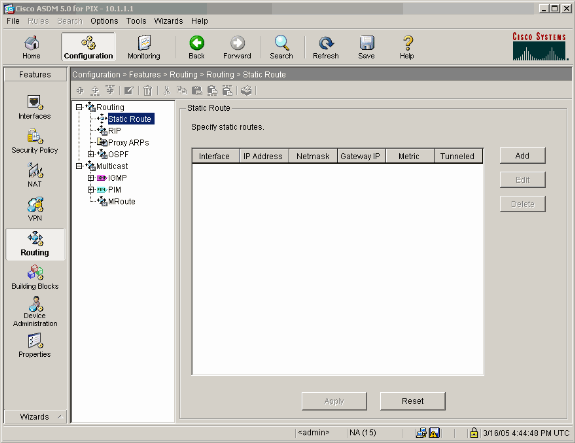
Features(기능) 탭에서 Routing(라우팅)을 클릭하고 Static Route(고정 경로)를 강조 표시한 후 Add(추가)를 클릭합니다.
-
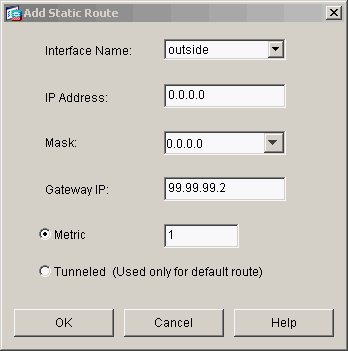
기본 게이트웨이를 구성하고 OK(확인)를 클릭합니다.
-
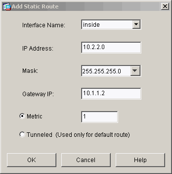
Add(추가)를 클릭하고 Inside networks(내부 네트워크)에 경로를 추가합니다.
-
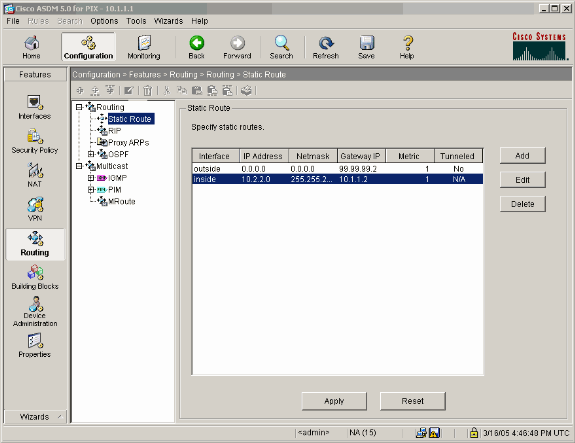
올바른 경로가 구성되었는지 확인하고 Apply를 클릭합니다.
-
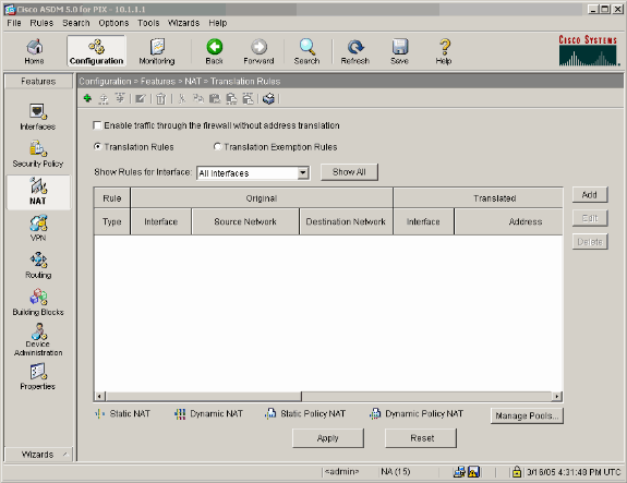
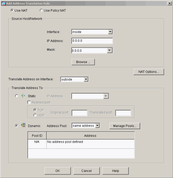
이 예에서는 NAT가 사용됩니다. Enable traffic through the firewall without address translation(주소 변환 없이 방화벽 통과 트래픽 활성화) 확인란을 제거하고 Add(추가)를 클릭하여 NAT 규칙을 구성합니다.
-
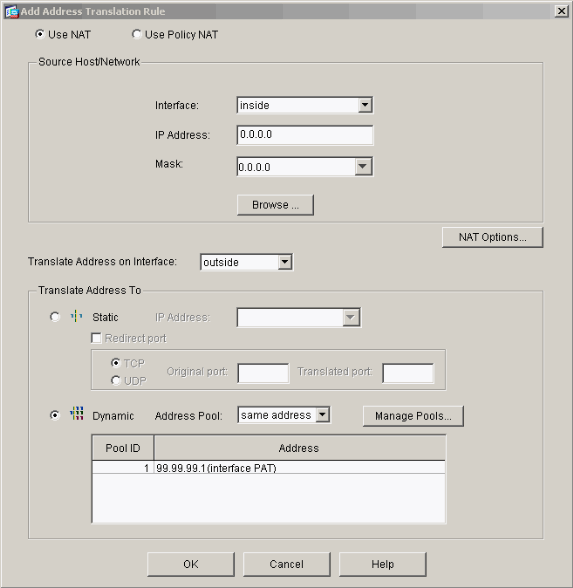
소스 네트워크를 구성합니다(이 예에서는 any를 사용합니다). 그런 다음 Manage Pools(풀 관리)를 클릭하여 PAT를 정의합니다.
-
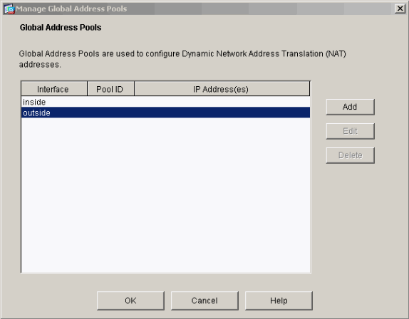
외부 인터페이스를 선택하고 Add를 클릭합니다.
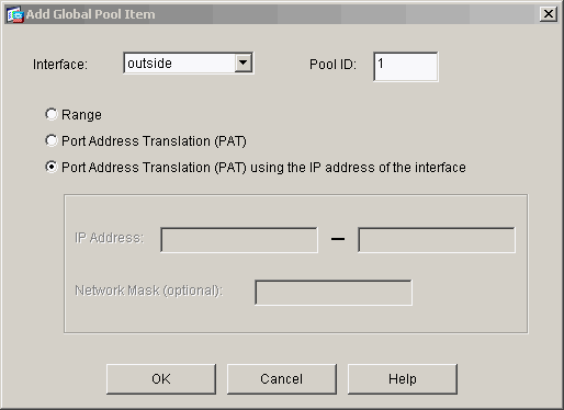
이 예에서는 인터페이스의 IP 주소를 사용하는 PAT를 사용합니다.
-
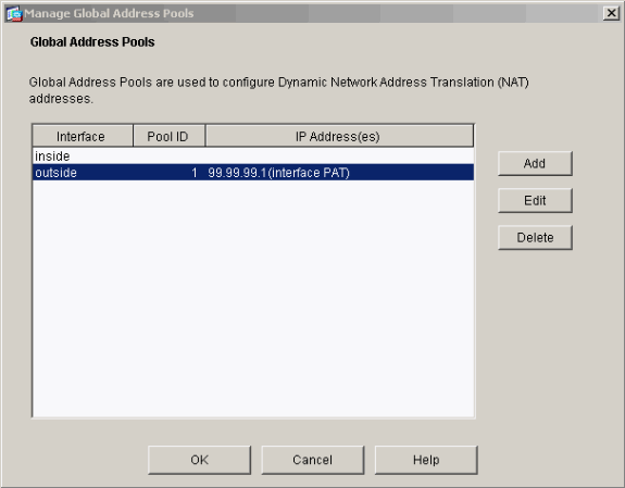
PAT가 구성되면 OK를 클릭합니다.
-
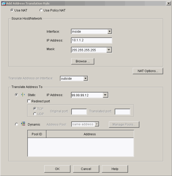
고정 변환을 구성하려면 Add를 클릭합니다.
-
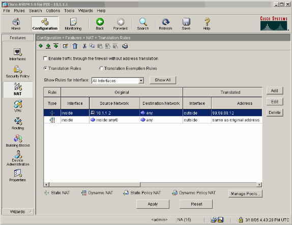
Interface(인터페이스) 드롭다운에서 inside(내부)를 선택한 다음 IP 주소 10.1.1.2, 서브넷 마스크 255.255.255.255를 입력하고 Static(정적)을 선택하고 IP Address(IP 주소) 필드에 outside address 99.99.99.12를 입력합니다. 완료되면 OK(확인)를 클릭합니다.
-
Apply(적용)를 클릭하여 인터페이스 컨피그레이션을 수락합니다. 컨피그레이션도 PIX에 푸시됩니다.
-
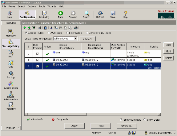
보안 정책 규칙을 구성하려면 Features(기능) 탭에서 Security Policy(보안 정책)를 선택합니다.
-
Add(추가)를 클릭하여 esp 트래픽을 허용하고 OK(확인)를 클릭하여 계속 진행합니다.
-
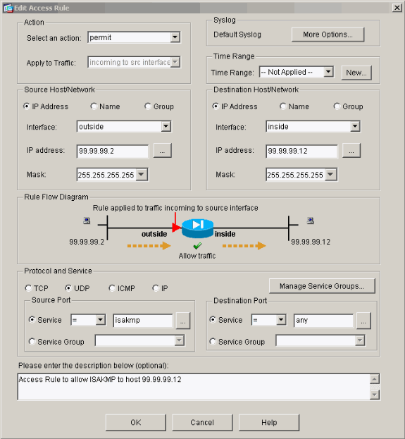
ISAKMP 트래픽을 허용하려면 Add(추가)를 클릭하고 계속하려면 OK(확인)를 클릭합니다.
-
NAT-T에 대해 UDP 포트 4500 트래픽을 허용하려면 Add(추가)를 클릭하고 계속하려면 OK(확인)를 클릭합니다.
-
인터페이스 컨피그레이션을 수락하려면 Apply를 클릭합니다. 컨피그레이션도 PIX에 푸시됩니다.
-
이제 구성이 완료되었습니다.
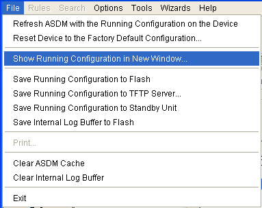
CLI 컨피그레이션을 보려면 File(파일) > Show Running Configuration in New Window(새 창에서 실행 중인 컨피그레이션 표시)를 선택합니다.
PIX 방화벽 컨피그레이션
| PIX 방화벽 |
|---|
pixfirewall# show run
: Saved
:
PIX Version 7.0(0)102
names
!
interface Ethernet0
 nameif outside
 security-level 0
 ip address 99.99.99.1 255.255.255.0
!
interface Ethernet1
 nameif inside
 security-level 100
 ip address 10.1.1.1 255.255.255.0
!
enable password 2KFQnbNIdI.2KYOU encrypted
passwd 2KFQnbNIdI.2KYOU encrypted
hostname pixfirewall
domain-name cisco.com
ftp mode passive

access-list outside_access_in remark Access Rule to Allow ESP traffic
access-list outside_access_in
            extended permit esp host 99.99.99.2 host 99.99.99.12

access-list outside_access_in
            remark Access Rule to allow ISAKMP to host 99.99.99.12
access-list outside_access_in
            extended permit udp host 99.99.99.2 eq isakmp host 99.99.99.12


access-list outside_access_in
            remark Access Rule to allow port 4500 (NAT-T) to host 99.99.99.12
access-list outside_access_in
                    extended permit udp host 99.99.99.2 eq 4500 host 99.99.99.12
pager lines 24
mtu inside 1500
mtu outside 1500
no failover
monitor-interface inside
monitor-interface outside
asdm image flash:/asdmfile.50073
no asdm history enable
arp timeout 14400
nat-control
global (outside) 1 interface
nat (inside) 0 0.0.0.0 0.0.0.0
static (inside,outside) 99.99.99.12 10.1.1.2 netmask 255.255.255.255
access-group outside_access_in in interface outside
route inside 10.2.2.0 255.255.255.0 10.1.1.2 1
route outside 0.0.0.0 0.0.0.0 99.99.99.2 1
timeout xlate 3:00:00
timeout conn 1:00:00 half-closed 0:10:00 udp 0:02:00 icmp 0:00:02
sunrpc 0:10:00 h323 0:05:00 h225 1:00:00 mgcp 0:05:00 mgcp-pat
0:05:00 sip 0:30:00 sip_media 0:02:00
timeout uauth 0:05:00 absolute
http server enable
http 10.1.1.3 255.255.255.255 inside
no snmp-server location
no snmp-server contact
snmp-server enable traps snmp
telnet timeout 5
ssh timeout 5
console timeout 0
!
class-map inspection_default
 match default-inspection-traffic
!
!
policy-map asa_global_fw_policy
 class inspection_default
  inspect dns maximum-length 512
  inspect ftp
  inspect h323 h225
  inspect h323 ras
  inspect netbios
  inspect rsh
  inspect rtsp
  inspect skinny
  inspect esmtp
  inspect sqlnet
  inspect sunrpc
  inspect tftp
  inspect sip
  inspect xdmcp
!
service-policy asa_global_fw_policy global
Cryptochecksum:0a12956036ce4e7a97f351cde61fba7e
: end |
PIX Security Appliance 및 MPF(Modular Policy Framework) 컨피그레이션
PIX/ASA 보안 어플라이언스를 통해 IPsec 트래픽을 전달하려면 액세스 목록 대신 MPF(Modular Policy Framework)에서 inspect ipsec-pass-thru 명령을 사용합니다.
이 검사는 ESP 트래픽에 대한 핀홀을 열도록 구성됩니다. 모든 ESP 데이터 흐름은 전달 흐름이 있을 때 허용되며, 허용할 수 있는 최대 연결 수에는 제한이 없습니다. AH는 허용되지 않습니다. ESP 데이터 흐름에 대한 기본 유휴 시간 제한은 기본적으로 10분으로 설정됩니다. 이 검사는 다른 검사가 적용될 수 있는 모든 위치에 적용할 수 있으며, 여기에는 class 및 match 명령 모드가 포함됩니다. IPSec Pass Through 애플리케이션 검사는 IKE UDP 포트 500 연결과 연결된 ESP(IP 프로토콜 50) 트래픽의 편리한 통과를 제공합니다. ESP 트래픽을 허용하기 위해 긴 액세스 목록 컨피그레이션을 피하고 시간 초과 및 최대 연결 수를 보장하는 보안을 제공합니다. 트래픽의 클래스를 정의하고, 클래스에 inspect 명령을 적용하고, 하나 이상의 인터페이스에 정책을 적용하려면 class-map, policy-map 및 service-policy 명령을 사용합니다. 활성화되면 inspect IPSec-pass-thru 명령은 10분의 시간 제한으로 무제한 ESP 트래픽을 허용하며, 이는 구성할 수 없습니다. NAT 및 비 NAT 트래픽은 허용됩니다.
hostname(config)#access-list test-udp-acl extended permit udp any any eq 500
hostname(config)#class-map test-udp-class
hostname(config-cmap)#match access-list test-udp-acl
hostname(config)#policy-map test-udp-policy
hostname(config-pmap)#class test-udp-class
hostname(config-pmap-c)#inspect ipsec-pass-thru
hostname(config)#service-policy test-udp-policy interface outside
다음을 확인합니다.
이 섹션에서는 컨피그레이션이 제대로 작동하는지 확인하는 데 사용할 수 있는 정보를 제공합니다.
일부 show 명령은 출력 인터프리터 툴 에서 지원되는데(등록된 고객만), 이 툴을 사용하면 show 명령 출력의 분석 결과를 볼 수 있습니다.
-
show crypto ipsec sa - 2단계 보안 연결을 표시합니다.
-
show crypto isakmp sa - 1단계 보안 연결을 표시합니다.
-
show crypto engine connections active - 암호화된 패킷과 해독된 패킷을 표시합니다.
문제 해결
이 섹션에서는 설정 문제 해결에 사용할 수 있는 정보를 제공합니다.
라우터 IPsec에 대한 트러블슈팅 명령
참고: debug 명령을 실행하기 전에 Debug 명령에 대한 중요 정보를 참조하십시오.
-
debug crypto engine — 암호화된 트래픽을 표시합니다.
-
debug crypto ipsec - 2단계의 IPsec 협상을 표시합니다.
-
debug crypto isakmp - 1단계의 ISAKMP(Internet Security Association and Key Management Protocol) 협상을 표시합니다.
보안 연결 지우기
-
clear crypto isakmp - IKE(Internet Key Exchange) 보안 연결을 지웁니다.
-
clear crypto ipsec sa - IPsec 보안 연결을 지웁니다.
PIX용 문제 해결 명령
일부 show 명령은 출력 인터프리터 툴 에서 지원되는데(등록된 고객만), 이 툴을 사용하면 show 명령 출력의 분석 결과를 볼 수 있습니다.
참고: debug 명령을 실행하기 전에 Debug 명령에 대한 중요 정보를 참조하십시오.
-
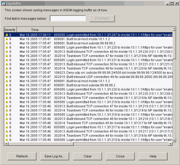
logging buffer debugging - PIX를 통과하는 호스트에 대한 연결이 설정 및 거부되고 있음을 표시합니다. 정보는 PIX 로그 버퍼에 저장되며, 출력은 show log 명령을 사용하여 확인할 수 있습니다.
-
ASDM을 사용하여 로깅을 활성화하고 다음 단계에 표시된 대로 로그를 볼 수 있습니다.
-
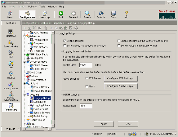
Configuration(컨피그레이션) > Properties(속성) > Logging(로깅) > Logging Setup(로깅 설정) > Enable Logging(로깅 활성화)을 선택하고 Apply(적용)를 클릭합니다.
-
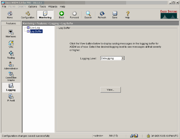
Monitoring(모니터링) > Logging(로깅) > Log Buffer(로그 버퍼) > On Logging Level(로깅 레벨) > Logging Buffer(로깅 버퍼)를 선택한 다음 View(보기)를 클릭합니다.
로그 버퍼의 예입니다.
관련 정보
개정 이력
| 개정 | 게시 날짜 | 의견 |
|---|---|---|
1.0 |
27-Jan-2005 |
최초 릴리스 |
 피드백
피드백