Cat9500 및 ISR4K 간 VPLS 설정

다운로드 옵션
편견 없는 언어
본 제품에 대한 문서 세트는 편견 없는 언어를 사용하기 위해 노력합니다. 본 설명서 세트의 목적상, 편견 없는 언어는 나이, 장애, 성별, 인종 정체성, 민족 정체성, 성적 지향성, 사회 경제적 지위 및 교차성에 기초한 차별을 의미하지 않는 언어로 정의됩니다. 제품 소프트웨어의 사용자 인터페이스에서 하드코딩된 언어, RFP 설명서에 기초한 언어 또는 참조된 서드파티 제품에서 사용하는 언어로 인해 설명서에 예외가 있을 수 있습니다. 시스코에서 어떤 방식으로 포용적인 언어를 사용하고 있는지 자세히 알아보세요.
이 번역에 관하여
Cisco는 전 세계 사용자에게 다양한 언어로 지원 콘텐츠를 제공하기 위해 기계 번역 기술과 수작업 번역을 병행하여 이 문서를 번역했습니다. 아무리 품질이 높은 기계 번역이라도 전문 번역가의 번역 결과물만큼 정확하지는 않습니다. Cisco Systems, Inc.는 이 같은 번역에 대해 어떠한 책임도 지지 않으며 항상 원본 영문 문서(링크 제공됨)를 참조할 것을 권장합니다.
소개
VPLS는 대부분의 고객이 ISP의 서비스와 타사 벤더를 통한 대여/리스 서비스에서 사용하는 레이어 2 확장 기술입니다. VPLS의 사용은 이 컨피그레이션 가이드의 범위를 벗어납니다. 이 가이드는 고객이 기존 ISR4K 플랫폼과 새로운 Cat9500 스위치 간에 L2VPN을 구성할 수 있도록 돕기 위한 기본 구성 가이드입니다.
사전 요구 사항
기본 L2VPN 개념 및 L2 VFI 컨텍스트 구성을 위한 의사 와이어 템플릿 구성에 대해 알고 있어야 합니다
요구 사항
ISR4K 라우터(모든 ISR4400/ISR4300), Cat9500 스위치 및 CE 디바이스로 사용 중인 디바이스 2개
사용되는 구성 요소
ISR4451-X
C9500-40X-A
CISCO1921
CISCO 2911
구성
컨피그레이션에서는 VPLS 컨텍스트 및 지원되는 VC 유형/세부 정보의 사용법을 알려줍니다
네트워크 다이어그램
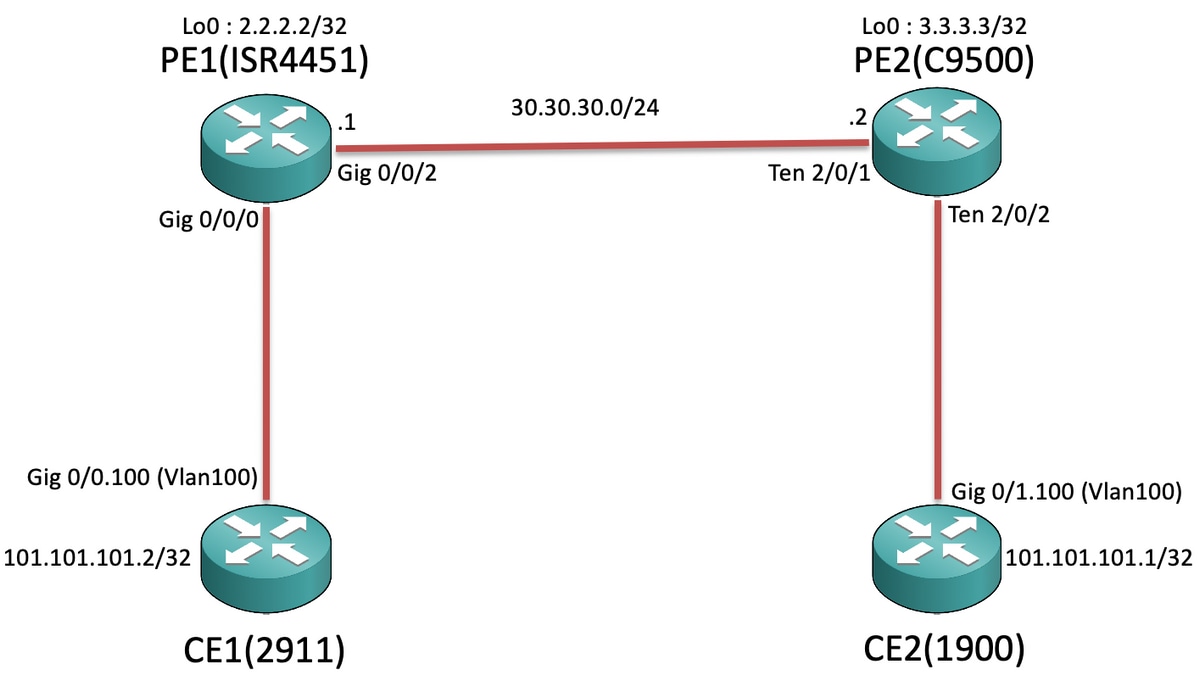
설정
CE1 및 CE2에서:
CE1#sh run Building configuration... Current configuration : 105 bytes ! interface GigabitEthernet0/0 no ip address duplex auto speed auto ! interface GigabitEthernet0/0.100 encapsulation dot1Q 100 ip address 101.101.101.2 255.255.255.0 ! |
CE2#sh run Building configuration... Current configuration : 1718 bytes ! interface GigabitEthernet0/1 no ip address duplex auto speed auto ! interface GigabitEthernet0/1.100 encapsulation dot1Q 100 ip address 101.101.101.1 255.255.255.0 ! |
PE1 및 PE2에서
PE1#sh run Building configuration... Current configuration : 5049 bytes ! pseudowire-class VPLS100 encapsulation mpls no control-word ! l2 vfi 100 manual vpn id 100 bridge-domain 100 mtu 9180 neighbor 3.3.3.3 pw-class VPLS100 ! interface Loopback0 ip address 2.2.2.2 255.255.255.255 ! interface GigabitEthernet0/0/0 mtu 9180 no ip address negotiation auto service instance 100 ethernet encapsulation dot1q 100 rewrite ingress tag pop 1 symmetric bridge-domain 100 ! ! interface GigabitEthernet0/0/2 ip address 30.30.30.1 255.255.255.0 negotiation auto mpls ip ! ip route 3.3.3.3 255.255.255.255 30.30.30.2 ! mpls ldp router-id Loopback0 force ! |
PE2#sh run Building configuration... Current configuration : 10722 bytes ! ip routing ! pseudowire-class VPLS100 encapsulation mpls no control-word ! l2 vfi 100 manual vpn id 100 neighbor 2.2.2.2 pw-class VPLS100 ! interface Loopback0 ip address 3.3.3.3 255.255.255.255 ! interface TenGigabitEthernet2/0/1 no switchport ip address 30.30.30.2 255.255.255.0 mpls ip ! interface TenGigabitEthernet2/0/2 switchport trunk allowed vlan 100 switchport mode trunk ! interface Vlan100 no ip address xconnect vfi 100 ! ip route 2.2.2.2 255.255.255.255 30.30.30.1 ! mpls ldp router-id Loopback0 force ! |

참고: EFP(Ethernet Flow Point) 서비스 인스턴스에서 실행되는 ISR4K 및 ASR1000 디바이스에서 서브넷/브로드캐스트 도메인을 확장할 해당 SI(서비스 인스턴스) 아래에 "rewrite ingress tag pop 1 symmetric" 명령을 구성했는지 확인합니다. 그러면 ISR4K/ASR1k가 CE 끝에서 전송되는 태그(802.1Q Vlan Tag) 패킷을 수신할 수 있습니다.
다음을 확인합니다.
Cat9500 플랫폼은 지금까지 VPLS에서 "이더넷"과의 인터네트워킹을 지원합니다. 따라서 먼저 VC 유형이 이더넷인지 확인합니다(기본값).
PE1#show mpls l2transport binding
  Destination Address: 3.3.3.3,VC ID: 100
    Local Label:  19
        Cbit: 0,    VC Type: Ethernet,    GroupID: n/a
        MTU: 9180,   Interface Desc: n/a
        VCCV: CC Type: RA [2], TTL [3]
              CV Type: LSPV [2]
    Remote Label: 17
        Cbit: 0,    VC Type: Ethernet,    GroupID: 0
        MTU: 9180,   Interface Desc: n/a
        VCCV: CC Type: RA [2], TTL [3]
              CV Type: LSPV [2]
PE2#show mpls l2transport binding
  Destination Address: 2.2.2.2,VC ID: 100
    Local Label:  17
        Cbit: 0,    VC Type: Ethernet,    GroupID: n/a
        MTU: 9180,   Interface Desc: n/a
        VCCV: CC Type: RA [2], TTL [3]
              CV Type: LSPV [2]
    Remote Label: 19
        Cbit: 0,    VC Type: Ethernet,    GroupID: 0
        MTU: 9180,   Interface Desc: n/a
        VCCV: CC Type: RA [2], TTL [3]
              CV Type: LSPV [2]
이제 나머지 명령은 L2VPN VC를 확인하는 방법과 비슷합니다. 그러나 Cat9500에는 시스템 mtu가 있으므로 LAN 쪽을 향하는 개별 인터페이스 MTU 값을 수정할 수 없다는 점을 이해하는 것이 중요합니다. 따라서 MTU 값이 Cat9500 스위치에 구성된 시스템 mtu를 기반으로 협상되도록 ISR4K 플랫폼의 l2 vfi 컨텍스트에서 "mtu <>"를 명시적으로 구성해야 합니다.
PE2:
PE2#show system mtu
Global Ethernet MTU is 9180 bytes.
PE1:
PE1#show mpls l2transport vc detail
Local interface: VFI 100 vfi up
  Interworking type is Ethernet
  Destination address: 3.3.3.3, VC ID: 100, VC status: up
    Output interface: Gi0/0/2, imposed label stack {17}
    Preferred path: not configured
    Default path: active
    Next hop: 30.30.30.2
  Create time: 00:02:10, last status change time: 00:02:10
    Last label FSM state change time: 00:02:10
  Signaling protocol: LDP, peer 3.3.3.3:0 up
    Targeted Hello: 2.2.2.2(LDP Id) -> 3.3.3.3, LDP is UP
    Graceful restart: not configured and not enabled
    Non stop routing: not configured and not enabled
    Status TLV support (local/remote)   : enabled/supported
      LDP route watch                   : enabled
      Label/status state machine        : established, LruRru
      Last local dataplane   status rcvd: No fault
      Last BFD dataplane     status rcvd: Not sent
      Last BFD peer monitor  status rcvd: No fault
      Last local AC  circuit status rcvd: No fault
      Last local AC  circuit status sent: No fault
      Last local PW i/f circ status rcvd: No fault
      Last local LDP TLV     status sent: No fault
      Last remote LDP TLV    status rcvd: No fault
      Last remote LDP ADJ    status rcvd: No fault
    MPLS VC labels: local 19, remote 17
    Group ID: local n/a, remote 0
    MTU: local 9180, remote 9180
    Remote interface description:
  Sequencing: receive disabled, send disabled
  Control Word: Off
  SSO Descriptor: 3.3.3.3/100, local label: 19
  Dataplane:
    SSM segment/switch IDs: 8387/4289 (used), PWID: 4
  VC statistics:
    transit packet totals: receive 0, send 0
    transit byte totals:   receive 0, send 0
    transit packet drops:  receive 0, seq error 0, send 0
PE2:
PE2#show mpls l2transport vc detail
Local interface: VFI 100 vfi up
  Interworking type is Ethernet
  Destination address: 2.2.2.2, VC ID: 100, VC status: up
    Output interface: Te2/0/1, imposed label stack {19}
    Preferred path: not configured
    Default path: active
    Next hop: 30.30.30.1
  Create time: 01:02:03, last status change time: 00:03:09
    Last label FSM state change time: 00:03:09
  Signaling protocol: LDP, peer 2.2.2.2:0 up
    Targeted Hello: 3.3.3.3(LDP Id) -> 2.2.2.2, LDP is UP
    Graceful restart: not configured and not enabled
    Non stop routing: not configured and not enabled
    Status TLV support (local/remote)   : enabled/supported
      LDP route watch                   : enabled
      Label/status state machine        : established, LruRru
      Last local dataplane   status rcvd: No fault
      Last BFD dataplane     status rcvd: Not sent
      Last BFD peer monitor  status rcvd: No fault
      Last local AC  circuit status rcvd: No fault
      Last local AC  circuit status sent: No fault
      Last local PW i/f circ status rcvd: No fault
      Last local LDP TLV     status sent: No fault
      Last remote LDP TLV    status rcvd: No fault
      Last remote LDP ADJ    status rcvd: No fault
    MPLS VC labels: local 17, remote 19
    Group ID: local n/a, remote 0
    MTU: local 9180, remote 9180
    Remote interface description:
  Sequencing: receive disabled, send disabled
  Control Word: Off
  SSO Descriptor: 2.2.2.2/100, local label: 17
  Dataplane:
    SSM segment/switch IDs: 12297/8194 (used), PWID: 1
  VC statistics:
    transit packet totals: receive 0, send 0
    transit byte totals:   receive 0, send 0
    transit packet drops:  receive 0, seq error 0, send 0
이제 CE1에서 CE2로 ping을 시작할 때
CE1#ping 101.101.101.1 source 101.101.101.2
Type escape sequence to abort.
Sending 5, 100-byte ICMP Echos to 101.101.101.1, timeout is 2 seconds:
Packet sent with a source address of 101.101.101.2
!!!!!
Success rate is 100 percent (5/5), round-trip min/avg/max = 1/1/4 ms
그런 다음 패킷이 VPLS를 통해 이동하는지 확인하기 위해 VC 통계를 확인할 때:
PE1:
PE1#show mpls l2transport vc detail | sec statistics
  VC statistics:
    transit packet totals: receive 5, send 5
    transit byte totals:   receive 660, send 660
    transit packet drops:  receive 0, seq error 0, send 0
PE2:
PE2#show mpls l2transport vc detail | sec statistics
  VC statistics:
    transit packet totals: receive 5, send 5
    transit byte totals:   receive 680, send 680
    transit packet drops:  receive 0, seq error 0, send 0
문제 해결
이 문서에서는 ISR/ASR 라우터와 PE 노드 역할을 하는 Cat9500 스위치 간에 VPLS VC를 구성하는 동안 호환성 문제를 강조하기 위해 작성되었으므로 현재 문제 해결 단계는 없습니다.
 피드백
피드백