ASR 1000 OTV のユニキャスト隣接サーバの設定例
内容
概要
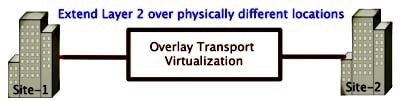
このドキュメントでは、Cisco アグリゲーション サービス ルータ(ASR)1000 プラットフォームでオーバーレイ トランスポート仮想化(OTV)Unicast Adjacency Server を設定する方法について説明します。従来の OTV では、インターネット サービス プロバイダー(ISP)クラウド上でマルチキャストが必要であるため、Unicast Adjacency Server により、マルチキャストのサポートと設定の要件に対応していない場合でも OTV 機能を使用できるようになります。
OTV により、物理的に異なるサイトにわたってレイヤ 2(L2)トポロジが拡張されます。これにより、デバイスはレイヤ 3(L3)プロバイダーにおいて L2 で通信できます。サイト 1 のデバイスは、デバイス自体がサイト 2 のデバイスと同じブロードキャスト ドメインにあると認識します。
前提条件
要件
次の項目に関する知識があることが推奨されます。
- イーサネット仮想コネクション(EVC)の設定
- ASR プラットフォームでの基本的な L2 と L3 の設定
使用するコンポーネント
このドキュメントの情報は、Cisco IOS® バージョン asr1000rp1-adventerprise.03.09.00.S.153-2.S.bin が動作する ASR 1002 に基づいています。
システムには、ASR 1000 およびシスコ クラウド サービス ルータ(CSR)1000V プラットフォームに OTV 機能を実装するために、以下が必須です。
- Cisco IOS-XE バージョン 3.9S またはこれ以降
- 1542 以上の最大伝送ユニット(MTU)
- サイト間のユニキャスト到達可能性
このドキュメントの情報は、特定のラボ環境にあるデバイスに基づいて作成されました。このドキュメントで使用するすべてのデバイスは、初期(デフォルト)設定の状態から起動しています。対象のネットワークが実稼働中である場合には、どのようなコマンドについても、その潜在的な影響について確実に理解しておく必要があります。
設定
基本的な L2/L3 接続を使用したネットワーク構成
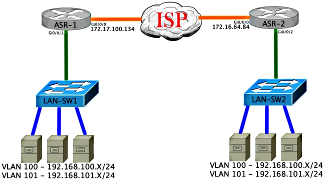
基本的な L2/L3 接続
基本設定から開始します。ASR の内部インターフェイスは、dot1q トラフィックのサービス インスタンスに対して設定されます。OTV 参加インターフェイスは、外部 WAN のレイヤ 3 インターフェイスです。
ASR-1
 interface GigabitEthernet0/0/0
  description OTV-WAN-Connection
  mtu 9216
  ip address 172.17.100.134 255.255.255.0
  negotiation auto
  cdp enable

 ASR-2
 interface GigabitEthernet0/0/0
  description OTV-WAN-Connection
  mtu 9216
  ip address 172.16.64.84 255.255.255.0
  negotiation auto
  cdp enable
OTV は 42 バイトのヘッダーを付加するため、ISP がサイト間で最小の MTU サイズを転送することを確認する必要があります。これを確認するには、DF ビットを設定したサイズが 1514 のパケットを送信します。これにより ISP には、必要なペイロードと、OTV パケットをシミュレートするための do not fragment タグがパケットで渡されます。DF ビットを設定せずに ping を発行できない場合は、ルーティングに問題があります。DF ビットを設定せずに ping を発行できるが、DF ビットを設定すると ping を発行できない場合は、MTU に問題があります。いずれも成功した場合は、ご使用のサイトの ASR に OTV ユニキャスト モードを追加する準備が整いました。
ASR-1#ping 172.17.100.134 size 1514 df-bit
 Type escape sequence to abort.
 Sending 5, 1514-byte ICMP Echos to 172.17.100.134, timeout is 2 seconds:
 Packet sent with the DF bit set
 !!!!!
 Success rate is 100 percent (5/5), round-trip min/avg/max = 1/1/2 ms
内部インターフェイスは、L2 dot1q タグ付きパケットのサービス インスタンスを使用して設定された L2 ポートです。これは内部サイトのブリッジ ドメインを作成します。この例では、タグなしVLAN1です。内部サイトブリッジドメインは、同じサイトにある複数のOTVデバイスの通信に使用されます。これにより、デバイス間の通信が可能になり、またどのデバイスがどのブリッジ ドメインの Authoritative Edge Device(AED)であるかが判定できます。
サービス インスタンスはオーバーレイを使用するブリッジ ドメインに設定する必要があります。
ASR-1
 interface GigabitEthernet0/0/1
  no ip address
  negotiation auto
  cdp enable
  service instance 1 ethernet
   encapsulation untagged
   bridge-domain 1
  !
  service instance 50 ethernet
   encapsulation dot1q 100
   bridge-domain 200
  !
  service instance 51 ethernet
   encapsulation dot1q 101
   bridge-domain 201


ASR-2
 interface GigabitEthernet0/0/2
  no ip address
  negotiation auto
  cdp enable
  service instance 1 ethernet
   encapsulation untagged
   bridge-domain 1
  !
  service instance 50 ethernet
   encapsulation dot1q 100
   bridge-domain 200
  !
  service instance 51 ethernet
   encapsulation dot1q 101
   bridge-domain 201
OTV ユニキャスト隣接関係サーバの最小構成
これは基本的な設定であり、隣接関係サーバおよび参加インターフェイスや内部インターフェイスをセットアップするのに数行のコマンドしか必要としません。
ローカル サイトのブリッジ ドメインを設定します。この例では、LAN 上の VLAN1 です。サイトIDは各物理ロケーションに固有です。この例では、物理的に独立した2つのリモートロケーションがあります。したがって、サイト 1 とサイト 2 を設定します。
ASR-1

 Config t
 otv site bridge-domain 1
 otv site-identifier 0000.0000.0001


ASR-2

 Config t
 otv site bridge-domain 1
 otv site-identifier 0000.0000.0002
それぞれにオーバーレイを作成します。オーバーレイを設定し、参加インターフェイスを適用して、それぞれに隣接関係サーバ設定を追加します。この例では、隣接サーバが ASR-1、クライアントが ASR-2 です。
拡張する 2 つのブリッジ ドメインを追加します。サイトのブリッジ ドメインを拡張するのではなく、必要な 2 つの VLAN のみを拡張することに注意してください。ブリッジドメイン200および201を呼び出すために、オーバーレイインターフェイス用に別のサービスインスタンスを作成します。dot1qタグ100および101をそれぞれ適用します。
ASR-1

 Config t
 interface Overlay1
  no ip address
  otv join-interface GigabitEthernet0/0/0
  otv use-adjacency-server 172.17.100.134 unicast-only
  otv adjacency-server unicast-only
    service instance 10 ethernet
     encapsulation dot1q 100
     bridge-domain 200
    service instance 11 ethernet
     encapsulation dot1q 101
     bridge-domain 201


ASR-2

 Config t
 interface Overlay1
  no ip address
  otv join-interface GigabitEthernet0/0/0
  otv use-adjacency-server 172.17.100.134 unicast-only
    service instance 10 ethernet
     encapsulation dot1q 100
     bridge-domain 200
    service instance 11 ethernet
     encapsulation dot1q 101
     bridge-domain 201
この段階で、ASR 間の OTV ユニキャストのみの隣接関係が完成し、使用できるようになっています。ネイバーが見つけられ、拡張する必要のある VLAN の AED 機能が ASR で使用できる必要があります。
ASR-1#show otv
 Overlay Interface Overlay1
  VPN name                 : None
  VPN ID                   : 1
  State                    : UP
  AED Capable              : Yes
  Join interface(s)        : GigabitEthernet0/0/0
  Join IPv4 address        : 172.17.100.134
  Tunnel interface(s)      : Tunnel0
  Encapsulation format     : GRE/IPv4
  Site Bridge-Domain       : 1
  Capability               : Unicast-only
  Is Adjacency Server      : Yes
  Adj Server Configured    : Yes
 Prim/Sec Adj Svr(s)      :172.17.100.134
 ASR-1#show otv isis neigh

 Tag Overlay1:
 System Id      Type Interface   IP Address      State Holdtime Circuit Id
 ASR-2          L1   Ov1         172.16.64.84      UP    25       ASR-1.01


ASR-2#show otv
 Overlay Interface Overlay1
  VPN name                 : None
  VPN ID                   : 1
  State                    : UP
  AED Capable              : Yes
  Join interface(s)        : GigabitEthernet0/0/0
  Join IPv4 address        : 172.16.64.84
  Tunnel interface(s)      : Tunnel0
  Encapsulation format     : GRE/IPv4
  Site Bridge-Domain       : 1
  Capability               : Unicast-only
  Is Adjacency Server      : No
  Adj Server Configured    : Yes
  Prim/Sec Adj Svr(s)      : 172.17.100.134
 ASR-2#show otv isis neigh

 Tag Overlay1:
 System Id      Type Interface   IP Address      State Holdtime Circuit Id
 ASR-1          L1   Ov1         172.17.100.134    UP    8        ASR-1.01
検証
ここでは、設定が正常に機能しているかどうかを確認します。
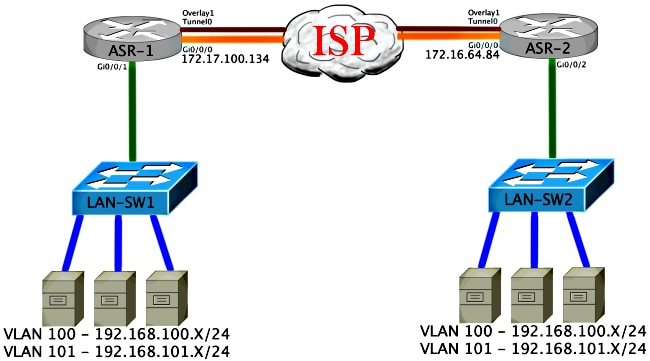
OTV によるネットワーク構成図
検証コマンドと想定される出力
この出力では、VLAN 100 と 101 が拡張されていることが示されています。ASR は AED であり、内部インターフェイスと、VLAN をマッピングするサービス インスタンスが出力に表示されています。
ASR-1#show otv vlan
 Key:  SI - Service Instance

 Overlay 1 VLAN Configuration Information
  Inst VLAN  Bridge-Domain  Auth  Site Interface(s)
  0    100   200            yes   Gi0/0/1:SI50
  0    101   201            yes   Gi0/0/1:SI51
  Total VLAN(s): 2
  Total Authoritative VLAN(s): 2


 ASR-2#show otv vlan
 Key:  SI - Service Instance

 Overlay 1 VLAN Configuration Information
  Inst VLAN  Bridge-Domain  Auth  Site Interface(s)
  0    100   200            yes   Gi0/0/2:SI50
  0    101   201            yes   Gi0/0/2:SI51
  Total VLAN(s): 2
  Total Authoritative VLAN(s): 2
VLAN が拡張されていることを確認するために、サイト間で ping を実行します。ホスト192.168.100.2はサイト1にあり、ホスト192.168.100.3はサイト2にあります。最初のいくつかのpingは、ローカルおよびOTVを介して他方の側にARPを構築すると失敗すると予想されます。
LAN-SW1#ping 192.168.100.3
 Type escape sequence to abort.
 Sending 5, 100-byte ICMP Echos to 192.168.100.3, timeout is 2 seconds:
 ...!!
 Success rate is 40 percent (2/5), round-trip min/avg/max = 1/5/10 ms


LAN-SW1#ping 192.168.100.3
 Type escape sequence to abort.
 Sending 5, 100-byte ICMP Echos to 192.168.100.3, timeout is 2 seconds:
 !!!!!
 Success rate is 100 percent (5/5), round-trip min/avg/max = 1/4/10 ms


LAN-SW1#ping 192.168.100.3 size 1500 df-bit
 Type escape sequence to abort.
 Sending 5, 1500-byte ICMP Echos to 192.168.100.3, timeout is 2 seconds:
 Packet sent with the DF bit set
 !!!!!
 Success rate is 100 percent (5/5), round-trip min/avg/max = 1/4/10 ms
ローカル デバイスを含む MAC テーブルと OTV のルーティング テーブルが適切に作成されたことを確認し、さらにリモート デバイスの MAC アドレスを把握するためには、show otv route コマンドを使用します。
LAN-SW1#show int vlan 100
 Vlan100 is up, line protocol is up
   Hardware is Ethernet SVI, address is 0c27.24cf.abd1 (bia 0c27.24cf.abd1)
   Internet address is 192.168.100.2/24


LAN-SW2#show int vlan 100
 Vlan100 is up, line protocol is up
   Hardware is Ethernet SVI, address is b4e9.b0d3.6a51 (bia b4e9.b0d3.6a51)
   Internet address is 192.168.100.3/24


ASR-1#show otv route vlan 100

 Codes: BD - Bridge-Domain, AD - Admin-Distance,
        SI - Service Instance, * - Backup Route

 OTV Unicast MAC Routing Table for Overlay1

  Inst VLAN BD     MAC Address    AD    Owner  Next Hops(s)
 ----------------------------------------------------------
  0    100  200    0c27.24cf.abaf 40    BD Eng Gi0/0/1:SI50
  0    100  200    0c27.24cf.abd1 40    BD Eng Gi0/0/1:SI50 <--- Local mac is
  pointing to the physical interface
  0    100  200    b4e9.b0d3.6a04 50    ISIS   ASR-2
  0    100  200    b4e9.b0d3.6a51 50    ISIS   ASR-2              <--- Remote
  mac is pointing across OTV to ASR-2

 4 unicast routes displayed in Overlay1

 ----------------------------------------------------------
 4 Total Unicast Routes Displayed


ASR-2#show otv route vlan 100

 Codes: BD - Bridge-Domain, AD - Admin-Distance,
        SI - Service Instance, * - Backup Route

 OTV Unicast MAC Routing Table for Overlay1

  Inst VLAN BD     MAC Address    AD    Owner  Next Hops(s)
 ----------------------------------------------------------
  0    100  200    0c27.24cf.abaf 50    ISIS   ASR-1
  0    100  200    0c27.24cf.abd1 50    ISIS   ASR-1              <--- Remote
  mac is pointing across OTV to ASR-1
  0    100  200    b4e9.b0d3.6a04 40    BD Eng Gi0/0/2:SI50
  0    100  200    b4e9.b0d3.6a51 40    BD Eng Gi0/0/2:SI50 <--- Local mac is
  pointing to the physical interface

 4 unicast routes displayed in Overlay1

 ----------------------------------------------------------
 4 Total Unicast Routes Displayed
一般的な問題
「When OTV Does Not Form」というエラー メッセージが出力に表示された場合、ASR で AED が使用できていません。つまり、ASR は OTV を介して VLAN を転送していません。これには複数の原因が考えられますが、一般的には、サイト間で ASR が接続されていないことが原因です。L3 接続と、OTV 用に予約されている UDP ポート 8472 へのトラフィックがブロックされている可能性がないかを確認します。この状況で考えられる別の原因として、内部サイトのブリッジ ドメインが設定されていない場合があります。このような場合には、ASR がそのサイトの唯一の ASR であることが確実ではないため、ASR は AED になれません。
ASR-1#show otv
 Overlay Interface Overlay1
  VPN name                 : None
  VPN ID                   : 1
  State                    : UP
  AED Capable              : No, overlay DIS not elected <--- Local OTV site cannot
  see the remote neighbor
  Join interface(s)        : GigabitEthernet0/0/0
  Join IPv4 address        : 172.17.100.134
  Tunnel interface(s)      : Tunnel0
  Encapsulation format     : GRE/IPv4
  Site Bridge-Domain       : 1
  Capability               : Unicast-only
  Is Adjacency Server      : Yes
  Adj Server Configured    : Yes
  Prim/Sec Adj Svr(s)      : 172.17.100.134


ASR-2#show otv
 Overlay Interface Overlay1
  VPN name                 : None
  VPN ID                   : 1
  State                    : UP
  AED Capable              : No, overlay DIS not elected <--- Local OTV site cannot
  see the remote neighbor
  Join interface(s)        : GigabitEthernet0/0/0
  Join IPv4 address        :172.16.64.84
  Tunnel interface(s)      : Tunnel0
  Encapsulation format     : GRE/IPv4
  Site Bridge-Domain       : 1
  Capability               : Unicast-only
  Is Adjacency Server      : No
  Adj Server Configured    : Yes
  Prim/Sec Adj Svr(s)      : 172.17.100.134
トラブルシュート
ここでは、設定のトラブルシューティングに使用できる情報を示します。
OTV Hellos を表示するための参加インターフェイスでのパケット キャプチャ作成
考えられる問題のトラブルシューティングに役立てるために、ASR の内蔵パケット キャプチャ デバイスが利用できます。
アクセス コントロール リスト(ACL)を作成してキャプチャの影響と負荷を最小とするために、次を入力します。
ip access-list extended CAPTURE
 permit udp host 172.17.100.134 host 172.16.64.84 eq 8472
 permit udp host 172.16.64.84 host 172.17.100.134 eq 8472
両方の ASR の双方向の参加インターフェイスをスニファするようにキャプチャをセットアップするために、次を入力します。
monitor capture 1 buffer circular access-list CAPTURE interface g0/0/0 both
キャプチャを開始するには、次を入力します。
monitor capture 1 start

 *Nov 14 15:21:37.746: %BUFCAP-6-ENABLE: Capture Point 1 enabled.

 <wait a few min>

 monitor capture 1 stop

 *Nov 14 15:22:03.213: %BUFCAP-6-DISABLE: Capture Point 1 disabled.

 show mon cap 1 buffer brief
バッファ出力には、キャプチャ内の Hellos がネイバーから、およびローカルで入力および出力されることが表示されます。キャプチャが両方の ASR で有効にされ、双方向でキャプチャされている場合、同じパケットが一方から出力され他方に入力していることがキャプチャに表示されます。
ASR-1 の最初の 2 つのパケットは ASR-2 では検出されなかったため、その時間と ASR-1 の出力に先立つ 2 つの余分なパケットに対応するために、キャプチャに 3 秒のオフセットを設定する必要があります。
ASR-1#show mon cap 1 buff bri
  -------------------------------------------------------------
  #   size   timestamp     source             destination   protocol
  -------------------------------------------------------------
    0 1464    0.000000   172.17.100.134     ->  172.16.64.84       UDP  * not in
    ASR-2 cap
    1  150    0.284034   172.17.100.134     ->  172.16.64.84       UDP  * not in
    ASR-2 cap
    2 1464    3.123047   172.17.100.134     ->  172.16.64.84       UDP
    3 1464    6.000992   172.17.100.134     ->  172.16.64.84       UDP
    4  110    6.140044   172.17.100.134     ->  172.16.64.84       UDP
    5 1464    6.507029   172.16.64.84       ->  172.17.100.134     UDP
    6 1464    8.595022   172.17.100.134     ->  172.16.64.84       UDP
    7  150    9.946994   172.17.100.134     ->  172.16.64.84       UDP
    8 1464   11.472027   172.17.100.134     ->  172.16.64.84       UDP
    9  110   14.600012   172.17.100.134     ->  172.16.64.84       UDP
   10 1464   14.679018   172.17.100.134     ->  172.16.64.84       UDP
   11 1464   15.696015   172.16.64.84       ->  172.17.100.134     UDP
   12 1464   17.795009   172.17.100.134     ->  172.16.64.84       UDP
   13  150   18.903997   172.17.100.134     ->  172.16.64.84       UDP
   14 1464   21.017989   172.17.100.134     ->  172.16.64.84       UDP
   15  110   23.151045   172.17.100.134     ->  172.16.64.84       UDP
   16 1464   24.296026   172.17.100.134     ->  172.16.64.84       UDP
   17 1464   25.355029   172.16.64.84       ->  172.17.100.134     UDP
   18 1464   27.053998   172.17.100.134     ->  172.16.64.84       UDP
   19  150   27.632023   172.17.100.134     ->  172.16.64.84       UDP
   20 1464   30.064999   172.17.100.134     ->  172.16.64.84       UDP
   21  110   32.358035   172.17.100.134     ->  172.16.64.84       UDP
   22 1464   32.737013   172.17.100.134     ->  172.16.64.84       UDP
   23 1464   32.866004   172.16.64.84       ->  172.17.100.134     UDP
   24 1464   35.338032   172.17.100.134     ->  172.16.64.84       UDP
   25  150   35.709015   172.17.100.134     ->  172.16.64.84       UDP
   26 1464   38.054990   172.17.100.134     ->  172.16.64.84       UDP
   27  110   40.121048   172.17.100.134     ->  172.16.64.84       UDP
   28 1464   41.194042   172.17.100.134     ->  172.16.64.84       UDP
   29 1464   42.196041   172.16.64.84       ->  172.17.100.134     UDP


ASR-2#show mon cap 1 buff bri
  -------------------------------------------------------------
  #   size   timestamp     source             destination   protocol
  -------------------------------------------------------------
    0 1464    0.000000   172.17.100.134     ->  172.16.64.84       UDP
    1 1464    2.878952   172.17.100.134     ->  172.16.64.84       UDP
    2  110    3.018004   172.17.100.134     ->  172.16.64.84       UDP
    3 1464    3.383982   172.16.64.84       ->  172.17.100.134     UDP
    4 1464    5.471975   172.17.100.134     ->  172.16.64.84       UDP
    5  150    6.824954   172.17.100.134     ->  172.16.64.84       UDP
    6 1464    8.349988   172.17.100.134     ->  172.16.64.84       UDP
    7  110   11.476980   172.17.100.134     ->  172.16.64.84       UDP
    8 1464   11.555971   172.17.100.134     ->  172.16.64.84       UDP
    9 1464   12.572968   172.16.64.84       ->  172.17.100.134     UDP
   10 1464   14.672969   172.17.100.134     ->  172.16.64.84       UDP
   11  150   15.780965   172.17.100.134     ->  172.16.64.84       UDP
   12 1464   17.895965   172.17.100.134     ->  172.16.64.84       UDP
   13  110   20.027998   172.17.100.134     ->  172.16.64.84       UDP
   14 1464   21.174002   172.17.100.134     ->  172.16.64.84       UDP
   15 1464   22.231998   172.16.64.84       ->  172.17.100.134     UDP
   16 1464   23.930951   172.17.100.134     ->  172.16.64.84       UDP
   17  150   24.508976   172.17.100.134     ->  172.16.64.84       UDP
   18 1464   26.942959   172.17.100.134     ->  172.16.64.84       UDP
   19  110   29.235995   172.17.100.134     ->  172.16.64.84       UDP
   20 1464   29.614973   172.17.100.134     ->  172.16.64.84       UDP
   21 1464   29.743964   172.16.64.84       ->  172.17.100.134     UDP
   22 1464   32.215992   172.17.100.134     ->  172.16.64.84       UDP
   23  150   32.585968   172.17.100.134     ->  172.16.64.84       UDP
   24 1464   34.931958   172.17.100.134     ->  172.16.64.84       UDP
   25  110   36.999008   172.17.100.134     ->  172.16.64.84       UDP
   26 1464   38.072002   172.17.100.134     ->  172.16.64.84       UDP
   27 1464   39.072994   172.16.64.84       ->  172.17.100.134     UDP
関連情報
更新履歴
| 改定 | 発行日 | コメント |
|---|---|---|
1.0 |
25-Apr-2014
|
初版 |
 フィードバック