Ejemplo de Configuración de Implementación de VSS de Supervisor Quad en Switches Catalyst 4500
Opciones de descarga
-
ePub (184.7 KB)
Visualice en diferentes aplicaciones en iPhone, iPad, Android, Sony Reader o Windows Phone -
Mobi (Kindle) (184.8 KB)
Visualice en dispositivo Kindle o aplicación Kindle en múltiples dispositivos
Lenguaje no discriminatorio
El conjunto de documentos para este producto aspira al uso de un lenguaje no discriminatorio. A los fines de esta documentación, "no discriminatorio" se refiere al lenguaje que no implica discriminación por motivos de edad, discapacidad, género, identidad de raza, identidad étnica, orientación sexual, nivel socioeconómico e interseccionalidad. Puede haber excepciones en la documentación debido al lenguaje que se encuentra ya en las interfaces de usuario del software del producto, el lenguaje utilizado en función de la documentación de la RFP o el lenguaje utilizado por un producto de terceros al que se hace referencia. Obtenga más información sobre cómo Cisco utiliza el lenguaje inclusivo.
Acerca de esta traducción
Cisco ha traducido este documento combinando la traducción automática y los recursos humanos a fin de ofrecer a nuestros usuarios en todo el mundo contenido en su propio idioma. Tenga en cuenta que incluso la mejor traducción automática podría no ser tan precisa como la proporcionada por un traductor profesional. Cisco Systems, Inc. no asume ninguna responsabilidad por la precisión de estas traducciones y recomienda remitirse siempre al documento original escrito en inglés (insertar vínculo URL).
Contenido
Introducción
Este documento describe cómo configurar el Supervisor Virtual Switching System (VSS) en el Catalyst 4500. El Supervisor VSS cuádruple ha sido una opción en el Catalyst 6500 desde hace unos años, sin embargo, esta tecnología es nueva en el Catalyst 4500 y puede que no funcione de la forma en que está acostumbrado.
Es posible instalar cuatro supervisores (2 por cada chasis) y crear una configuración VSS de cuatro puertos. En esta configuración, un chasis contiene un supervisor que actúa como VSS activo y es responsable del plano de control de toda la configuración de VSS, mientras que el otro supervisor del mismo chasis actúa como en espera dentro del chasis (ICS). El segundo chasis contiene un supervisor que actúa como VSS Standby (es decir, un supervisor al que VSS conmutará por error en caso de fallo activo de VSS) mientras que el otro actúa como ICS.
El comportamiento de VSS de Quad-SUP en el Catalyst 4500 depende de la versión de Cisco IOS XE® que se utiliza. Originalmente para configuraciones VSS de cuatro puertos, los supervisores ICS permanecen en ROMMON en cualquier momento con todos los puertos de enlace ascendente capaces de reenviar datos. No existe ningún mecanismo automático para que ICS se haga cargo automáticamente (es decir, participe en VSS desde la perspectiva del plano de control) en caso de fallo.
En la versión 03.08.00E y posterior, el Catalyst 4500 admite supervisores ICS en el modo Redundancia de procesador de routing (RPR) que mejora la funcionalidad de cuádruple sup y el comportamiento de failover en caso de falla del supervisor, lo que permite la conmutación por fallas automática entre todos los supervisores en caso de falla.
Prerequisites
Requirements
Cisco recomienda que conozca la tecnología VSS antes de instalar cuatro supervisores.
Para configurar un VSS de supervisor cuádruple en el Catalyst 4500 con Supervisor 7, sus supervisores necesitan ejecutar Cisco IOS XE versión 3.4.0 o posterior. También deberá asegurarse de que su versión ROM es 15.0(1r) SG7 o posterior.
Para configurar quad supervisor VSS en Catalyst 4500 con Supervisor 8, sus supervisores necesitan ejecutar Cisco IOS XE versión 3.6.0 o posterior. También deberá asegurarse de que su versión ROM es 15.1(1r) SG4 o posterior.
Para configurar quad supervisor VSS en el Catalyst 4500 con ICS que se ejecuta en modo RPR, sus supervisores necesitan ejecutar Cisco IOS XE versión 3.8.0 o posterior. También deberá asegurarse de que su versión ROM es 15.1(1r)SG6 o posterior.
La redundancia de Stateful Switchover (SSO) entre supervisores activos en el chasis requiere el nivel de licencia de Base IP o de Servicios empresariales.
Componentes Utilizados
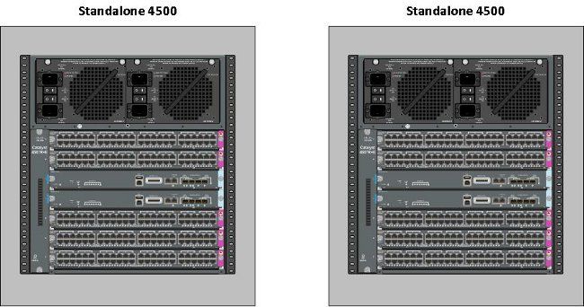
La información de este documento se basa en dos chasis Catalyst 4507R+E que contienen Supervisor 7Es redundante.
Cisco recomienda que el enlace de switch virtual (VSL) esté formado por conexiones redundantes. En este ejemplo, hay links 10G redundantes entre cada supervisor.
En la versión 03.08.00E y anteriores, Cisco NO soporta "activo en espera" mientras se encuentra en quad supervisor VSS. El supervisor redundante en cada chasis permanecerá en ROMMON y tendrá que arrancarse manualmente tras una falla del supervisor principal. En la versión 03.08.00E y posteriores, los supervisores de ICS estarán en modo RPR.
The information in this document was created from the devices in a specific lab environment. All of the devices used in this document started with a cleared (default) configuration. If your network is live, make sure that you understand the potential impact of any command.
Compatibilidad con chasis asimétrico
Catalyst 4500 y Catalyst 4500-X VSS requieren el mismo tipo de motor supervisor en ambos chasis. El chasis debe contener el mismo número de ranuras, incluso si sus tarjetas de línea difieren o sus ranuras están vacías. Siempre que el número de ranuras en los dos chasis coincida, el chasis puede variar en el tipo (es decir, el chasis +E y -E puede estar en un único VSS).
Configurar
Verificar antes de empezar
Para implementar quad supervisor VSS en el Catalyst 4500, utilice el Supervisor 8 para asegurarse de que haya algunas configuraciones en su lugar:
- Asegúrese de que se cumplen los requisitos mínimos de software. Este ejemplo muestra la versión 03.08.01E con la versión ROM 15.1(1r)SG6.
4K_SW1#show version | i Cisco IOS Software|ROM: Cisco IOS Software, IOS-XE Software, Catalyst 4500 L3 Switch Software
(cat4500es8-UNIVERSALK9-M), Version 03.08.01.E RELEASE SOFTWARE (fc2) ROM: 15.1(1r)SG6 - Asegúrese de que los supervisores actuales estén todos en el modo de redundancia SSO.
Nota: Se requiere un nivel mínimo de licencia de Base IP para SSO (Base LAN sólo se ejecutará en RPR).
4K_SW1#show redundancy
Redundant System Information :

------------------------------
       Available system uptime = 1 day, 10 hours, 4 minutes
Switchovers system experienced = 0
              Standby failures = 0
        Last switchover reason = none

                 Hardware Mode = Duplex
    Configured Redundancy Mode = Stateful Switchover
     Operating Redundancy Mode = Stateful Switchover
              Maintenance Mode = Disabled
Communications = Up - Asegúrese de que la variable de registro de inicio correcta esté configurada para asegurarse de que el switch se inicie como se esperaba.Cisco recomienda 0x2102 como valor de registro de configuración. Esto asegura que el switch se inicie a la versión de Cisco IOS XE mencionada en la sentencia de inicio.
4K_SW1#show bootvar
BOOT variable = bootflash:cat4500es8-universalk9.SPA.03.08.01.E.152-4.E1.bin,1;
CONFIG_FILE variable =
BOOTLDR variable =
Configuration register is 0x2102

Standby BOOT variable = bootflash:cat4500es8-universalk9.SPA.03.08.01.E.152-4.E1.bin,1;
Standby CONFIG_FILE variable =
Standby BOOTLDR variable =
Standby Configuration register is 0x2102
Cable and Configure
En este ejemplo, se utilizan cuatro conexiones de fibra de 10 G entre cada chasis para formar el VSL. Las conexiones utilizan los puertos 10G de los supervisores.
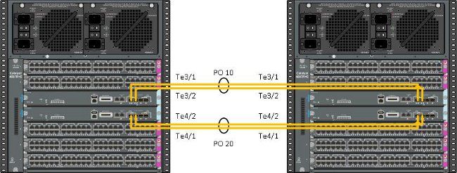
Nota: Hay varias maneras de cablear esta solución y el ejemplo aquí es sólo una manera posible.
Complete estos pasos para configurar los switches:
- Configure el dominio virtual y el número de switch en cada switch. Los números de dominio virtual del switch configurados en los dos switches DEBEN ser idénticos.
4K_SW1(config)#switch virtual domain 200
Domain ID 200 config will take effect only
after the exec command 'switch convert mode virtual' is issued

4K_SW1(config-vs-domain)#switch 1
4K_SW2(config)#switch virtual domain 200
Domain ID 200 config will take effect only
after the exec command 'switch convert mode virtual' is issued

4K_SW2(config-vs-domain)#switch 2 - Cree los canales de puerto y agregue los links de miembro. A diferencia de la numeración de dominio mostrada anteriormente, los números de canal de puerto NO DEBEN ser idénticos.
4K_SW1(config)#int po10
4K_SW1(config-if)#switchport
4K_SW1(config-if)#switchport mode trunk
4K_SW1(config-if)#switch virtual link 1
4K_SW1(config-if)#exit

4K_SW1(config)#int range te3/1-2, te4/1-2
4K_SW1(config-if-range)#switchport mode trunk
4K_SW1(config-if-range)#channel-group 10 mode on

WARNING: Interface TenGigabitEthernet3/1 placed in restricted config mode.
 All extraneous configs removed!

*Jul  3 19:36:00.615: %EC-5-CANNOT_BUNDLE2: Te3/1 is not compatible with Po10
 and will be suspended (trunk mode of Te3/1 is dynamic, Po10 is trunk)

4K_SW1#show etherchannel summary

Group  Port-channel  Protocol    Ports
------+-------------+-----------+-----------------------------------------------
10     Po10(SD)         -        Te3/1(w)    Te3/2(w)    Te4/1(w)
Te4/2(w)4K_SW2(config)#int po20
4K_SW2(config-if)#switchport
4K_SW2(config-if)#switchport mode trunk
4K_SW2(config-if)#switch virtual link 2
4K_SW2(config)#int range te3/1-2, te4/1-2
4K_SW2(config-if-range)#switchport mode trunk
4K_SW2(config-if-range)#channel-group 20 mode on
WARNING: Interface TenGigabitEthernet3/2 placed in restricted config mode.
All extraneous configs removed!
*Jul 3 19:50:26.703: %EC-5-CANNOT_BUNDLE2: Te3/1 is not compatible with
Po20 and will be suspended (trunk mode of Te3/1 is dynamic, Po20 is trunk)
4K_SW2#show etherchannel summary
Group Port-channel Protocol Ports
------+-------------+-----------+-----------------------------------------------
20 Po20(SD) - Te3/1(w) Te3/2(w) Te4/1(w)
Te4/2(w)Nota: El error "%EC-5-CANNOT_BUNDLE2" es transitorio y se puede ignorar de forma segura.
Convertir los switches en virtuales (RPR Mode/03.08.00E y posteriores)
1. Guarde la configuración en ambos switches, que sincronizarán la configuración en los supervisores dentro del chasis.
4K_SW1#copy running-config startup-config
4K_SW2#copy running-config startup-config
2. Convierta el chasis en modo VSS:
Switch#switch convert mode virtual

This command will convert all interface names
to naming convention "interface-type switch-number/slot/port",
save the running config to startup-config and
reload the switch.
Do you want to proceed? [yes/no]: yes
Converting interface names
Esto provoca una recarga del chasis. Durante la recarga en el chasis ICS, se muestra este mensaje y la consola dejará de estar disponible:
***********************************
*  IN-CHASSIS STANDBY SUPERVISOR  *
*     REDUNDANCY mode is RPR      *
* Waiting for Switchover Activity *
***********************************
Convertir los switches en virtuales (modo ROMMON / anterior a la versión 03.08.00E)
Los switches ahora deben convertirse en VSS; sin embargo, a diferencia de un único supervisor VSS tradicional, el proceso requiere que se cree cada conjunto de supervisores.
1. Recargue el supervisor de peer en cada chasis y manténgalo en espera en ROMMON.
Nota: Debe asegurarse de que tiene acceso a la consola en el supervisor y puede detener rápidamente el proceso de inicio.
Supervisores activos en cada chasis
4K_SW1#redundancy reload peer
Reload peer [confirm]
4K_SW1#
Preparing to reload peer
Supervisores de iguales en cada chasis
***** The system will autoboot in 5 seconds *****


 Type control-C to prevent autobooting.
 . .
 Autoboot cancelled......... please wait!!!
rommon 1 > [interrupt]

rommon 1 >
Ambos chasis deben tener un supervisor activo y un supervisor en el estado ROMMON antes de continuar. A continuación, ingrese el comando switch Convert mode virtual para convertir los dos supervisores activos en VSS.
4K_SW1#switch convert mode virtual

This command will convert all interface names
to naming convention "interface-type switch-number/slot/port",
save the running config to startup-config and
reload the switch.

Do you want to proceed? [yes/no]: yes
Converting interface names
Building configuration...
Compressed configuration from 6329 bytes to 2912 bytes[OK]
Saving converted configuration to bootflash: ...
Destination filename [startup-config.converted_vs-20140704-053736]?

7146 bytes copied in 1.404 secs (5090 bytes/sec)
Rebooting the switch

*Jul  4 05:37:40.501: %SYS-5-RELOAD: Reload requested by Exec.
 Reload Reason: Reason unspecified.
4K_SW2#switch convert mode virtual

This command will convert all interface names
to naming convention "interface-type switch-number/slot/port",
save the running config to startup-config and
reload the switch.

Do you want to proceed? [yes/no]: yes
Converting interface names
Building configuration...
Compressed configuration from 5819 bytes to 2786 bytes[OK]
Saving converted configuration to bootflash: ...
Destination filename [startup-config.converted_vs-20140704-053752]?
5831 bytes copied in 0.416 secs (14017 bytes/sec)
Rebooting the switch

*Jul  4 05:37:54.072: %SYS-5-RELOAD: Reload requested by Exec.
 Reload Reason: Reason unspecified.
Nota: Los puertos de switch en los supervisores de peer pasan tráfico activamente incluso cuando el supervisor está en estado ROMMON.
Una vez que los supervisores se han convertido y recargado en VSS, el siguiente paso es colocarlos en un estado ROMMON y convertir los supervisores de peer en VSS. Dado que los supervisores activos están en VSS, simplemente puede ejecutar un único comando para volver a cargar el estante completo. No olvide detenerlos en ROMMON.
4K_SW1#redundancy reload shelf
Reload the entire shelf [confirm]
Preparing to reload this shelf

<Snippet>

***** The system will autoboot in 5 seconds *****


 Type control-C to prevent autobooting.
 .
 Autoboot cancelled......... please wait!!!
rommon 1 > [interrupt]

rommon 1 >
Una vez que los supervisores activos anteriormente se detienen en ROMMON, inicie manualmente los supervisores de peer y conviértalos en VSS.
Una vez que los dos supervisores se inician y están activos, debe realizar algunos cambios de configuración para asegurarse de que los nuevos supervisores se unan al VSS. Recuerde que los supervisores de peer se recargaron antes de la conversión a VSS, por lo que no pueden analizar parte de la configuración al cargar. La forma más segura de asegurarse de que se aplica toda la configuración es repetir los pasos realizados anteriormente. Es posible que también tenga que establecer de forma predeterminada las interfaces antes de volver a configurar el canal de puerto.
4K_SW1(config)#switch virtual domain 200
4K_SW1(config-vs-domain)#switch 1

4K_SW1(config)#int po10
4K_SW1(config-if)#switchport
4K_SW1(config-if)#switchport mode trunk
4K_SW1(config-if)#switch virtual link 1

MESSAGE:
You are configuring VSL on interface Po10.
There are member ports already attached to the port channel.
Remove all member ports before configuring as VSL Port-Channel.
Supervisor activo
4K_SW1(config)#default int range te3/1-2, te4/1-2
Volver a aplicar la configuración al canal de puerto 10
4K_SW1(config)#int po10
4K_SW1(config-if)#switch virtual link 1

*Jul  4 07:25:29.532: %SPANTREE-6-PORTDEL_ALL_VLANS: Port-channel10
 deleted from all Vlans
Configurar puertos de miembro
4K_SW1(config)#int range te3/1-2,te4/1-2
4K_SW1(config-if-range)#switchport mode trunk
4K_SW1(config-if-range)#channel-group 10 mode on
Volver a aplicar la configuración al canal de puerto 20
4K_SW2(config)#int po20
4K_SW2(config-if)#switch virtual link 2

*Jul  4 07:35:29.532: %SPANTREE-6-PORTDEL_ALL_VLANS: Port-channel20 deleted from all Vlans
Configurar puertos de miembro
4K_SW2(config)#int range te3/1-2,te4/1-2
4K_SW2(config-if-range)#switchport mode trunk
4K_SW2(config-if-range)#channel-group 20 mode on
Convertir ambos switches en VSS
4K_SW1#switch convert mode virtual

This command will convert all interface names
to naming convention "interface-type switch-number/slot/port",
save the running config to startup-config and
reload the switch.

Do you want to proceed? [yes/no]: yes
Converting interface names
Building configuration...
Compressed configuration from 6329 bytes to 2911 bytes[OK]
Saving converted configuration to bootflash: ...
Destination filename [startup-config.converted_vs-20140704-080809]?
7146 bytes copied in 0.116 secs (61603 bytes/sec)

Rebooting the switch
4K_SW2#switch convert mode virtual

This command will convert all interface names
to naming convention "interface-type switch-number/slot/port",
save the running config to startup-config and
reload the switch.

Do you want to proceed? [yes/no]: yes
Converting interface names
Building configuration...
Compressed configuration from 5819 bytes to 2785 bytes[OK]
Saving converted configuration to bootflash: ...
Destination filename [startup-config.converted_vs-20140704-080834]?
5831 bytes copied in 0.984 secs (5926 bytes/sec)

Rebooting the switch
Una vez que los supervisores se recarguen, ahora deben formar en VSS. Ahora debe tener dos supervisores activos y dos supervisores que se sientan en ROMMON y esperan un arranque manual. Los supervisores de par permanecen en ROMMON y deben reiniciarse manualmente para aceptar el tráfico del plano de control.
Troubleshoot
Actualmente, no hay información específica de troubleshooting disponible para esta configuración.
Verificación
Use esta sección para confirmar que su configuración funciona correctamente.
4K_SW1#show switch virtual

Executing the command on VSS member switch role = VSS Active, id = 2


Switch mode                  : Virtual Switch
Virtual switch domain number : 200
Local switch number          : 2
Local switch operational role: Virtual Switch Active
Peer switch number           : 1
Peer switch operational role : Virtual Switch Standby

Executing the command on VSS member switch role = VSS Standby, id = 1


Switch mode                  : Virtual Switch
Virtual switch domain number : 200
Local switch number          : 1
Local switch operational role: Virtual Switch Standby
Peer switch number           : 2
Peer switch operational role : Virtual Switch Active
4K_SW1#show switch virtual redundancy

Executing the command on VSS member switch role = VSS Active, id = 2


                  My Switch Id = 2
                Peer Switch Id = 1
        Last switchover reason = user forced
    Configured Redundancy Mode = Stateful Switchover
     Operating Redundancy Mode = Stateful Switchover

Switch 2 Slot 14 Processor Information :
-----------------------------------------------
        Current Software state = ACTIVE
                 Image Version = Cisco IOS Software, Catalyst 4500 L3 Switch  Software
 (cat4500e-UNIVERSALK9-M), Version 15.2(2)E, RELEASE SOFTWARE (fc3)
Technical Support: http://www.cisco.com/techsupport
Copyright (c) 1986-2014 by Cisco Systems, Inc.
Compiled Fri 27-Jun-14 05:55 by prod_rel_team
                          BOOT = bootflash:cat4500e-universalk9.SPA.03.05.02.E.152-1.E2.bin,1;
        Configuration register = 0x102 (will be 0x2102 at next reload)
                  Fabric State = ACTIVE
           Control Plane State = ACTIVE

Switch 1 Slot 4 Processor Information :
-----------------------------------------------
        Current Software state = STANDBY HOT (switchover target)
                 Image Version = Cisco IOS Software, Catalyst 4500 L3 Switch  Software
 (cat4500e-UNIVERSALK9-M), Version 15.2(2)E, RELEASE SOFTWARE (fc3)
Technical Support: http://www.cisco.com/techsupport
Copyright (c) 1986-2014 by Cisco Systems, Inc.
Compiled Fri 27-Jun-14 05:55 by p
                          BOOT = bootflash:cat4500e-universalk9.SPA.03.05.02.E.152-1.E2.bin,1;
        Configuration register = 0x102 (will be 0x2102 at next reload)
                  Fabric State = ACTIVE
           Control Plane State = STANDBY


Executing the command on VSS member switch role = VSS Standby, id = 1

show virtual switch redundancy is not supported on the standby
Información Relacionada
Con la colaboración de ingenieros de Cisco
- Luke PrimmCisco TAC Engineer
- Mariusz KazmierskiCisco TAC Engineer
 Comentarios
Contacte a Cisco
- Abrir un caso de soporte

- (Requiere un Cisco Service Contract)