Introducción
Este documento describe el procedimiento de reemplazo de switches para Cisco Catalyst 4500 Series Switches que se ejecutan en el modo Virtual Switching System (VSS).
Prerequisites
Cisco recomienda que tenga conocimiento sobre estos temas:
- Cisco VSS
- VSS activo y VSS en espera
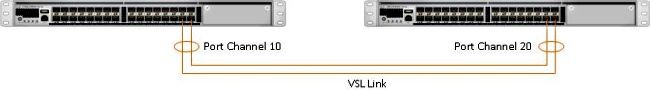
- Enlace de switch virtual (VSL)
Componentes Utilizados
La información de este documento se basa en el WS-C4500X-32 con Cisco IOS® versión 03.05.01. Sin embargo, el mismo proceso se puede aplicar a un chasis 4500 con Supervisor 7 Engine (Sup7).
La información que contiene este documento se creó a partir de los dispositivos en un ambiente de laboratorio específico. Todos los dispositivos que se utilizan en este documento se pusieron en funcionamiento con una configuración verificada (predeterminada). Si tiene una red en vivo, asegúrese de entender el posible impacto de cualquier comando.
Configurar
Nota: Cisco recomienda que, si es posible, la conversión a VSS se realice en una ventana de mantenimiento.
Paso 1: Identificación de funciones de switch
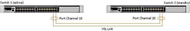
El primer paso es identificar el switch que debe ser reemplazado. En este ejemplo, debe sustituirse el interruptor activo (Switch 1). El comando show switch virtual proporciona la información activa y en espera.
4500X-VSS#show switch virtual

Executing the command on VSS member switch role = VSS Active, id = 1

Switch mode                  : Virtual Switch
Virtual switch domain number : 100
Local switch number          : 1
Local switch operational role: Virtual Switch Active
Peer switch number           : 2
Peer switch operational role : Virtual Switch Standby

Executing the command on VSS member switch role = VSS Standby, id = 2

Switch mode                  : Virtual Switch
Virtual switch domain number : 100
Local switch number          : 2
Local switch operational role: Virtual Switch Standby
Peer switch number           : 1
Peer switch operational role : Virtual Switch Active
Paso 2: Conmutación por fallo
Ahora, sabe qué switch está activo (Switch 1) y qué switch está en estado de espera (Switch 2). El siguiente paso es conmutar por error las responsabilidades del plano de control al Switch 2 para que pueda prepararse para el reemplazo del Switch 1. El comando redundancy force-switchover realiza la operación necesaria.
Nota: La redundancia de redundancia puede provocar tiempos de inactividad en función del estado de redundancia operativa. Tenga en cuenta que este paso recarga completamente el activo actual (Switch 1) para pasar las responsabilidades de control al par (Switch 2).
4500X-VSS#redundancy force-switchover
This will reload the active unit and force switchover to standby[confirm]
Preparing for switchover..

*Mar  2 13:38:06.553: %SYS-5-SWITCHOVER: Switchover requested by Exec. Reason:
  Stateful Switchover.
<Sun Mar  2 13:38:09 2014> Message from sysmgr: Reason Code:[3] Reset Reason:
  Reset/Reload requested by [console]. [Reload command]
Paso 3: Verificación de la conmutación por error
Antes de retirar el switch defectuoso, debe verificar que el sistema ha fallado completamente. Para verificar el estado de redundancia, ingrese el comando show redundancy.
4500X-VSS#show redundancy
Redundant System Information :

------------------------------
       Available system uptime = 1 week, 3 days, 22 hours, 37 minutes
Switchovers system experienced = 8
              Standby failures = 0
        Last switchover reason = user_forced

                 Hardware Mode = Duplex
    Configured Redundancy Mode = Stateful Switchover
     Operating Redundancy Mode = Stateful Switchover
              Maintenance Mode = Disabled
                Communications = Up

Current Processor Information :
------------------------------
               Active Location = slot 2/1
        Current Software state = ACTIVE
       Uptime in current state = 55 minutes
                 Image Version = Cisco IOS Software, Cisco IOS-XE Software, Catalyst
                                 4500 L3 Switch Software (cat4500e-UNIVERSAL-M),
                                 Version 03.05.01.E RELEASE SOFTWARE (fc2)
Technical Support: http://www.cisco.com/techsupport
Copyright (c) 1986-2013 by Cisco Systems, Inc.
Compiled Sat 23-Nov-13 00:46 by prod_re
               BOOT = bootflash:cat4500e-universal.SPA.03.05.01.E.152-1.E1.bin,1;
        Configuration register = 0x2102

Peer Processor Information :
------------------------------
              Standby Location = slot 1/1
        Current Software state = STANDBY HOT
       Uptime in current state = 0 minute
                 Image Version = Cisco IOS Software, Cisco IOS-XE Software,
                                 Catalyst 4500 L3 Switch Software (cat4500e-UNIVERSAL-M),
                                 Version 03.05.01.E RELEASE SOFTWARE (fc2)
Technical Support: http://www.cisco.com/techsupport
Copyright (c) 1986-2013 by Cisco Systems, Inc.
Compiled Sat 23-Nov-13 00:46 by prod_
               BOOT = bootflash:cat4500e-universal.SPA.03.05.01.E.152-1.E1.bin,1;
        Configuration register = 0x2102
En el resultado, el estado del software actual = STANDBY HOT muestra que el sistema se ha estabilizado y está totalmente sincronizado en este momento. Ahora puede continuar con la extracción física del switch.
Paso 4: Retirada del switch
En este momento, el switch fallido está listo para la extracción física. Es muy importante tener en cuenta que si su topología no es totalmente redundante tras la eliminación, puede sufrir un impacto en el servicio. Cisco recomienda implementar Multichassis EtherChannel (MEC) para garantizar que los enlaces permanecen activos.
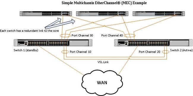
Nota: MEC es un EtherChannel con puertos que finalizan en ambos switches del VSS. Un VSS MEC puede conectarse a cualquier elemento de red que admita EtherChannel (como un host, un servidor, un router o un switch).
Paso 5 - Desarrollo e instalación del switch de reemplazo
Debe utilizar el mismo conjunto de características de licencia e imagen de Cisco IOS en el chasis en espera para este chasis para unirse correctamente al dominio VSS actual. Este ejemplo implica la descarga e instalación de la versión 03.05.01 para que coincida con el peer actual. Una vez instalados, los links físicos deben estar conectados en la ubicación exacta del switch que fue reemplazado y luego el switch debe ser iniciado. El switch ahora debe estar en línea con una configuración en blanco y en un estado autónomo ya que aún no se ha configurado como miembro de VSS.
Paso 6: Configuración y unión al VSS
Debe establecer el dominio VSS y el número de switch.
Nota: Esta es la misma información que habría utilizado el switch anterior. En este ejemplo, el dominio es 100 y el número de switch es 1.
4500X-VSS(config)#switch virtual domain 100
4500X-VSS(config-vs-domain)#switch 1
A continuación, debe configurar las interfaces físicas y los canales de puerto que se utilizan para el enlace VSL.
4500X-VSS(config)# interface Port-channel 10
4500X-VSS(config-if)#switchport
4500X-VSS(config-if)#switch virtual link 1
4500X-VSS(config)# int range tenGigabitEthernet 1/1/15-16
4500X-VSS(config-if-range) channel-group 10 mode on
Por último, debe convertir el modo de switch de independiente a virtual. Una vez realizada esta configuración, el switch se vuelve a cargar.
4500X-VSS# switch convert mode virtual
Cuando el switch 1 completa su recarga, detecta el switch VSS activo actual desde el link VSL y sincroniza automáticamente la configuración.
Verificación
Ahora los switches deben volver a estar en un sistema VSS totalmente redundante. El comando show switch virtual garantiza que cada switch esté en el estado correcto. Para verificar que está nuevamente en el stateful switchover (SSO), o en el estado hot standby, ingrese otro comando show redundancy.
4500X-VSS#show switch virtual

Executing the command on VSS member switch role = VSS Active, id = 2

Switch mode                  : Virtual Switch
Virtual switch domain number : 100
Local switch number          : 2
Local switch operational role: Virtual Switch Active
Peer switch number           : 1
Peer switch operational role : Virtual Switch Standby

Executing the command on VSS member switch role = VSS Standby, id = 1

Switch mode                  : Virtual Switch
Virtual switch domain number : 100
Local switch number          : 1
Local switch operational role: Virtual Switch Standby
Peer switch number           : 2
Peer switch operational role : Virtual Switch Active


4500X-VSS#show redundancy
Redundant System Information :

------------------------------
       Available system uptime = 1 week, 4 days, 9 hours, 27 minutes
Switchovers system experienced = 8
              Standby failures = 0
        Last switchover reason = user_forced

                 Hardware Mode = Duplex
    Configured Redundancy Mode = Stateful Switchover
     Operating Redundancy Mode = Stateful Switchover
              Maintenance Mode = Disabled
                Communications = Up

Current Processor Information :
------------------------------
               Active Location = slot 2/1
        Current Software state = ACTIVE
       Uptime in current state = 1 hours, 3 minutes
                 Image Version = Cisco IOS Software, Cisco IOS-XE Software, Catalyst 4500
                                 L3 Switch Software (cat4500e-UNIVERSAL-M), Version
                                 03.05.01.E RELEASE SOFTWARE (fc2)
Technical Support: http://www.cisco.com/techsupport
Copyright (c) 1986-2013 by Cisco Systems, Inc.
Compiled Sat 23-Nov-13 00:46 by prod_re
               BOOT = bootflash:cat4500e-universal.SPA.03.05.01.E.152-1.E1.bin,1;
        Configuration register = 0x2102

Peer Processor Information :
------------------------------
              Standby Location = slot 1/1
        Current Software state = STANDBY HOT
       Uptime in current state = 1 hours, 3 minutes
                 Image Version = Cisco IOS Software, Cisco IOS-XE Software, Catalyst 4500
                                 L3 Switch Software (cat4500e-UNIVERSAL-M), Version
                                 03.05.01.E RELEASE SOFTWARE (fc2)
Technical Support: http://www.cisco.com/techsupport
Copyright (c) 1986-2013 by Cisco Systems, Inc.
Compiled Sat 23-Nov-13 00:46 by prod_
               BOOT = bootflash:cat4500e-universal.SPA.03.05.01.E.152-1.E1.bin,1;
        Configuration register = 0x2102
Problemas Comunes
VSL permanece inactivo
Si la VSL permanece inactiva mientras uno o ambos switches terminan de arrancar, puede ingresar una situación activa dual si no existe un mecanismo de detección activo dual. El sistema permanece activo dual hasta que se detecta un supervisor de peer (a menudo activando el enlace VSL después de que el switch se haya iniciado). Una vez que se detecta la condición activa dual, uno de los supervisores se pone en modo de recuperación y apaga todas las interfaces locales al chasis en el que se encuentra. Una vez que el link VSL está completamente restaurado, el switch/supervisor en el modo de recuperación debe recargarse para que pueda renegociar correctamente como un modo en espera en el VSS.
Troubleshoot
Para verificar el link VSL, ingrese:
4500X-VSS#show switch virtual link

Executing the command on VSS member switch role = VSS Active, id = 2

VSL Status : UP
VSL Uptime : 11 hours, 53 minutes
VSL Control Link : Te2/1/1
VSL Encryption : Configured Mode - Off, Operational Mode - Off

Executing the command on VSS member switch role = VSS Standby, id = 1

VSL Status : UP
VSL Uptime : 11 hours, 53 minutes
VSL Control Link : Te1/1/1
VSL Encryption : Configured Mode - Off, Operational Mode - Off
Para que el VSS funcione con redundancia SSO, el VSS debe cumplir estas condiciones:
- Versiones de software idénticas en ambos switches
- consistencia de configuración VSL
En la secuencia de inicio, el switch VSS en espera envía información del switch virtual desde el archivo startup-config al switch VSS activo.
El switch activo de VSS garantiza que esta información coincida correctamente en ambos switches:
- Cambiar dominio virtual
- Nodo virtual del switch
- Prioridad de switch (opcional)
- Canal de puerto VSL: Switch Virtual Link Identifier
- Puertos VSL: channel-group number, shutdown, total number of VSL ports
Información Relacionada:
 Comentarios