Ejemplo de Configuración de Multicast de OTV ASR 1000
Contenido
Introducción
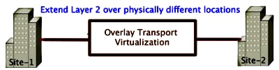
Este documento describe cómo configurar el modo multidifusión Overlay Transport Virtualization (OTV) en la plataforma Cisco Aggregation Services Router (ASR) 1000. OTV amplía la topología de capa 2 (L2) a los distintos sitios físicos, lo que permite a los dispositivos comunicarse en L2 a través de un proveedor de capa 3 (L3). Los dispositivos del Sitio 1 creen que se encuentran en el mismo dominio de difusión que los del Sitio 2.
Prerequisites
Requirements
Cisco recomienda que tenga conocimiento sobre estos temas:
- Configuración de conexión virtual Ethernet (EVC)
- Configuración básica de L2 y L3 en la plataforma ASR
- Conocimiento de configuración de protocolo básico de administración de grupos de Internet (IGMP) versión 3 y multidifusión independiente de protocolo (PIM)
Componentes Utilizados
La información en este documento se basa en el ASR1002 con Cisco IOS® versión asr1000rp1-adventerprise.03.09.00.S.153-2.S.bin.
El sistema debe tener estos requisitos para implementar la función OTV en el ASR 1000:
- Cisco IOS-XE versión 3.5S o posterior
- Unidad máxima de transmisión (MTU) de 1542 o superior
- Alcance de unidifusión y multidifusión entre sitios
The information in this document was created from the devices in a specific lab environment. All of the devices used in this document started with a cleared (default) configuration. If your network is live, make sure that you understand the potential impact of any command.
Configurar
Esta sección describe cómo configurar el modo de multidifusión OTV.
Diagrama de red con conectividad L2/L3 básica
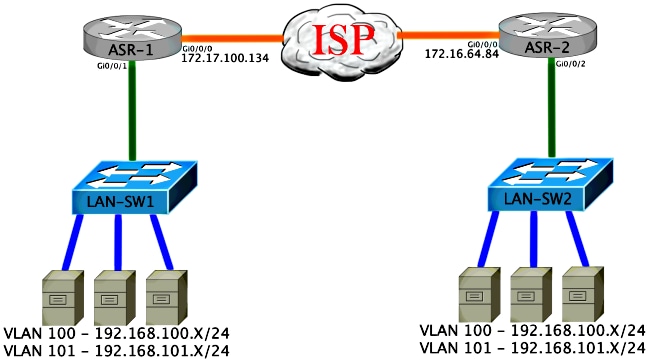
Conectividad básica de L2/L3
Comience con una configuración básica. La interfaz interna en el ASR se configura para instancias de servicio para el tráfico dot1q. La interfaz de unión de OTV es la interfaz WAN L3 externa.
ASR-1
interface GigabitEthernet0/0/0
  description OTV-WAN-Connection
  mtu 9216
  ip address 172.17.100.134 255.255.255.0
  negotiation auto
  cdp enable

ASR-2
interface GigabitEthernet0/0/0
  description OTV-WAN-Connection
  mtu 9216
  ip address 172.16.64.84 255.255.255.0
  negotiation auto
  cdp enable
Dado que OTV agrega un encabezado de 42 bytes, debe verificar que el proveedor de servicios de Internet (ISP) pasa el tamaño mínimo de MTU de sitio a sitio. Para lograr esta verificación, envíe un tamaño de paquete de 1542 con el bit DF configurado. Esto le da al ISP la carga útil requerida más la etiqueta no fragmentar en el paquete para simular un paquete OTV. Si no puede hacer ping sin el bit DF, entonces tiene un problema de ruteo. Si puede hacer ping sin él, pero no puede hacer ping con el bit DF configurado, tiene un problema de MTU. Una vez que tenga éxito, estará listo para agregar el modo de unidifusión OTV a los ASR de su sitio.
ASR-1#ping 172.17.100.134 size 1542 df-bit
 Type escape sequence to abort.
 Sending 5, 1514-byte ICMP Echos to 172.17.100.134, timeout is 2 seconds:
 Packet sent with the DF bit set
 !!!!!
 Success rate is 100 percent (5/5), round-trip min/avg/max = 1/1/2 ms
La interfaz interna es un puerto L2 configurado con instancias de servicio para los paquetes etiquetados con punto1q L2. También crea un dominio de puente de sitio interno. En este ejemplo, es la VLAN1 sin etiqueta. El dominio de puente de sitio interno se utiliza para la comunicación de varios dispositivos OTV en el mismo sitio. Esto les permite comunicarse y determinar qué dispositivo es el dispositivo perimetral autorizado (AED) para qué dominio de puente.
La instancia de servicio se debe configurar en un dominio de puente que utilice la superposición.
ASR-1
 interface GigabitEthernet0/0/1
  no ip address
  negotiation auto
  cdp enable
  service instance 1 ethernet
   encapsulation untagged
   bridge-domain 1
  !
  service instance 50 ethernet
   encapsulation dot1q 100
   bridge-domain 200
  !
  service instance 51 ethernet
   encapsulation dot1q 101
   bridge-domain 201


ASR-2
 interface GigabitEthernet0/0/2
  no ip address
  negotiation auto
  cdp enable
  service instance 1 ethernet
   encapsulation untagged
   bridge-domain 1
  !
  service instance 50 ethernet
   encapsulation dot1q 100
   bridge-domain 200
  !
  service instance 51 ethernet
   encapsulation dot1q 101
   bridge-domain 201
Configuración mínima de multidifusión de OTV
Esta es una configuración básica que requiere sólo unos cuantos comandos para configurar OTV y unir/interfaces internas.
Configure el dominio del puente del sitio local. En este ejemplo, es VLAN1 en la LAN. El identificador del sitio es específico para cada ubicación física. En este ejemplo, hay dos ubicaciones remotas que son físicamente independientes entre sí. El Sitio 1 y el Sitio 2 se configuran en consecuencia. La multidifusión también debe configurarse de acuerdo con los requisitos de OTV.
ASR-1

Config t
otv site bridge-domain 1
otv site-identifier 0000.0000.0001
ip multicast-routing distributed
ip pim ssm default
interface GigabitEthernet0/0/0
  ip pim passive
  ip igmp version 3


ASR-2

Config t
otv site bridge-domain 1
otv site-identifier 0000.0000.0002
ip multicast-routing distributed
ip pim ssm default
interface GigabitEthernet0/0/0
  ip pim passive
  ip igmp version 3
Construya la superposición para cada lado. Configure la superposición, aplique la interfaz de unión y agregue el control y los grupos de datos a cada lado.
Agregue los dos dominios de puente que desea extender. Observe que no amplía el dominio del puente del sitio, sólo las dos VLAN necesarias. Se crea una instancia de servicio independiente para que las interfaces de superposición llamen al dominio de puente 200 y 201. Aplique las etiquetas dot1q 100 y 101 respectivamente.
ASR-1

 Config t
 interface Overlay1
  no ip address
  otv join-interface GigabitEthernet0/0/0
  otv control-group 225.0.0.1  otv data-group 232.10.10.0/24
   service instance 10 ethernet
    encapsulation dot1q 100
    bridge-domain 200
   service instance 11 ethernet
    encapsulation dot1q 101
    bridge-domain 201


ASR-2

 Config t
 interface Overlay1
  no ip address
  otv join-interface GigabitEthernet0/0/0
  otv control-group 225.0.0.1  otv data-group 232.10.10.0/24
   service instance 10 ethernet
    encapsulation dot1q 100
    bridge-domain 200
   service instance 11 ethernet
    encapsulation dot1q 101
    bridge-domain 201
En esta etapa, la adyacencia de multidifusión ASR a ASR OTV es completa y funcional. Se encuentran los vecinos y el ASR debe tener capacidad AED para las VLAN que se deben ampliar.
ASR-1#show otv
Overlay Interface Overlay1
 VPN name                 : None
 VPN ID                   : 2
 State                    : UP
 AED Capable              : Yes
 IPv4 control group       : 225.0.0.1
 Mcast data group range(s): 232.10.10.0/24
 Join interface(s)        : GigabitEthernet0/0/0
 Join IPv4 address        : 172.17.100.134
 Tunnel interface(s)      : Tunnel0
 Encapsulation format     : GRE/IPv4
 Site Bridge-Domain       : 1
 Capability               : Multicast-reachable
 Is Adjacency Server      : No
 Adj Server Configured    : No
 Prim/Sec Adj Svr(s)      : None


ASR-2#show otv
Overlay Interface Overlay1
 VPN name                 : None
 VPN ID                   : 2
 State                    : UP
 AED Capable              : Yes
 IPv4 control group       : 225.0.0.1
 Mcast data group range(s): 232.10.10.0/24
 Join interface(s)        : GigabitEthernet0/0/0
 Join IPv4 address        : 172.16.64.84
 Tunnel interface(s)      : Tunnel0
 Encapsulation format     : GRE/IPv4
 Site Bridge-Domain       : 1
 Capability               : Multicast-reachable
 Is Adjacency Server      : No
 Adj Server Configured    : No
 Prim/Sec Adj Svr(s)      : None
Verificación de OTV
Utilize esta sección para confirmar que su configuración funcione correctamente.
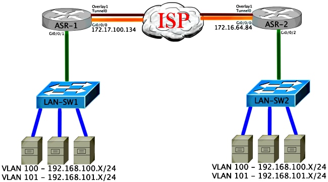
Diagrama de red con OTV
Comandos de verificación y salida esperada
Este resultado muestra que las VLAN 100 y 101 se extienden. El ASR es el AED, y la interfaz interna y la instancia de servicio que mapea las VLAN se muestran en el resultado.
ASR-1#show otv vlan
Key:  SI - Service Instance

Overlay 1 VLAN Configuration Information
 Inst VLAN  Bridge-Domain  Auth  Site Interface(s)
 0    100   200            yes   Gi0/0/1:SI50
 0    101   201            yes   Gi0/0/1:SI51
 Total VLAN(s): 2
 Total Authoritative VLAN(s): 2


ASR-2#show otv vlan
Key:  SI - Service Instance

Overlay 1 VLAN Configuration Information
 Inst VLAN  Bridge-Domain  Auth  Site Interface(s)
 0    100   200            yes   Gi0/0/2:SI50
 0    101   201            yes   Gi0/0/2:SI51
 Total VLAN(s): 2
 Total Authoritative VLAN(s): 2
Para validar, extienda las VLAN y realice un ping de sitio a sitio. El host 192.168.100.2 se encuentra en el Sitio 1, y el host 192.168.100.3 se encuentra en el Sitio 2. Se espera que los primeros pings fallen a medida que se genera el protocolo de resolución de direcciones (ARP) de forma local y a través de OTV al otro lado.
LAN-SW1#ping 192.168.100.3
 Type escape sequence to abort.
 Sending 5, 100-byte ICMP Echos to 192.168.100.3, timeout is 2 seconds:
 ...!!
 Success rate is 40 percent (2/5), round-trip min/avg/max = 1/5/10 ms


LAN-SW1#ping 192.168.100.3
 Type escape sequence to abort.
 Sending 5, 100-byte ICMP Echos to 192.168.100.3, timeout is 2 seconds:
 !!!!!
 Success rate is 100 percent (5/5), round-trip min/avg/max = 1/4/10 ms


LAN-SW1#ping 192.168.100.3 size 1500 df-bit
 Type escape sequence to abort.
 Sending 5, 1500-byte ICMP Echos to 192.168.100.3, timeout is 2 seconds:
 Packet sent with the DF bit set
 !!!!!
 Success rate is 100 percent (5/5), round-trip min/avg/max = 1/4/10 ms
Para asegurarse de que la tabla MAC y las tablas de ruteo OTV se construyan correctamente con el dispositivo local, aprenda la dirección MAC del dispositivo remoto con el uso del comando show otv route.
LAN-SW1#show int vlan 100
 Vlan100 is up, line protocol is up
   Hardware is Ethernet SVI, address is 0c27.24cf.abd1 (bia 0c27.24cf.abd1)
   Internet address is 192.168.100.2/24


LAN-SW2#show int vlan 100
 Vlan100 is up, line protocol is up
   Hardware is Ethernet SVI, address is b4e9.b0d3.6a51 (bia b4e9.b0d3.6a51)
   Internet address is 192.168.100.3/24


ASR-1#show otv route vlan 100

 Codes: BD - Bridge-Domain, AD - Admin-Distance,
        SI - Service Instance, * - Backup Route

 OTV Unicast MAC Routing Table for Overlay1

  Inst VLAN BD     MAC Address    AD    Owner  Next Hops(s)
 ----------------------------------------------------------
  0    100  200    0c27.24cf.abaf 40    BD Eng Gi0/0/1:SI50
  0    100  200    0c27.24cf.abd1 40    BD Eng Gi0/0/1:SI50 <--- Local mac is
  pointing to the physical interface
  0    100  200    b4e9.b0d3.6a04 50    ISIS   ASR-2
  0    100  200    b4e9.b0d3.6a51 50    ISIS   ASR-2        <--- Remote mac is
  pointing across OTV to ASR-2

 4 unicast routes displayed in Overlay1

 ----------------------------------------------------------
 4 Total Unicast Routes Displayed


ASR-2#show otv route vlan 100

 Codes: BD - Bridge-Domain, AD - Admin-Distance,
        SI - Service Instance, * - Backup Route

 OTV Unicast MAC Routing Table for Overlay1

  Inst VLAN BD     MAC Address    AD    Owner  Next Hops(s)
 ----------------------------------------------------------
  0    100  200    0c27.24cf.abaf 50    ISIS   ASR-1
  0    100  200    0c27.24cf.abd1 50    ISIS   ASR-1           <--- Remote mac is
  pointing across OTV to ASR-1
  0    100  200    b4e9.b0d3.6a04 40    BD Eng Gi0/0/2:SI50
  0    100  200    b4e9.b0d3.6a51 40    BD Eng Gi0/0/2:SI50    <--- Local mac is
  pointing to the physical interface

 4 unicast routes displayed in Overlay1

 ----------------------------------------------------------
 4 Total Unicast Routes Displayed
Problema común
El mensaje de error OTV no forma en la salida muestra que el ASR no es apto para AED. Esto significa que el ASR no reenvía las VLAN a través del OTV. Hay varias causas posibles para esto, pero la más común es que los ASR no tienen conectividad entre los sitios. Verifique la conectividad L3 y el posible tráfico multicast bloqueado. Otra causa posible de esta condición es cuando el dominio del puente del sitio interno no está configurado. Esto crea una condición en la que el ASR no puede convertirse en el AED, porque no es seguro si es el único ASR en el sitio o no.
ASR-1#show otv
Overlay Interface Overlay1
 VPN name                 : None
 VPN ID                   : 2
 State                    : UP
 AED Capable              : No, overlay DIS not elected       <--- Not Forwarding
 IPv4 control group       : 225.0.0.1
 Mcast data group range(s): 232.0.0.0/8
 Join interface(s)        : GigabitEthernet0/0/0
 Join IPv4 address        : 172.17.100.134
 Tunnel interface(s)      : Tunnel0
 Encapsulation format     : GRE/IPv4
 Site Bridge-Domain       : 1
 Capability               : Multicast-reachable
 Is Adjacency Server      : No
 Adj Server Configured    : No
 Prim/Sec Adj Svr(s)      : None


ASR-2#show otv
Overlay Interface Overlay1
 VPN name                 : None
 VPN ID                   : 2
 State                    : UP
 AED Capable              : No, overlay DIS not elected       <--- Not Forwarding
 IPv4 control group       : 225.0.0.1
 Mcast data group range(s): 232.0.0.0/8
 Join interface(s)        : GigabitEthernet0/0/0
 Join IPv4 address        : 172.16.64.84
 Tunnel interface(s)      : Tunnel0
 Encapsulation format     : GRE/IPv4
 Site Bridge-Domain       : 1
 Capability               : Multicast-reachable
 Is Adjacency Server      : No
 Adj Server Configured    : No
 Prim/Sec Adj Svr(s)      : None
Troubleshoot
En esta sección se brinda información que puede utilizar para resolver problemas en su configuración.
Cree una captura de paquetes en la interfaz de unión para ver los Hellos de OTV
Puede utilizar el dispositivo de captura de paquetes incorporado en el ASR para ayudar a resolver posibles problemas.
Cree una lista de control de acceso (ACL) para minimizar el impacto y las capturas saturadas. La configuración se configura para capturar solamente los saludos multicast entre dos sitios. Ajuste la dirección IP para que coincida con las interfaces de unión de los vecinos.
ip access-list extended CAPTURE
 permit ip host 172.16.64.84 host 225.0.0.1
 permit ip host 172.17.100.134 host 225.0.0.1
Configure la captura para rastrear la interfaz de unión en ambas direcciones en ambos ASR:
monitor capture 1 buffer circular access-list CAPTURE interface g0/0/0 both
Para iniciar la captura, ingrese:
monitor capture 1 start

 *Nov 14 15:21:37.746: %BUFCAP-6-ENABLE: Capture Point 1 enabled.

 <wait a few min>

 monitor capture 1 stop

 *Nov 14 15:22:03.213: %BUFCAP-6-DISABLE: Capture Point 1 disabled.

 show mon cap 1 buffer brief
La salida del búfer muestra que los saludos en la captura egresan la interfaz capturada. Muestra los saludos destinados a la dirección multicast 225.0.0.1. Este es el grupo de control configurado. Vea los primeros 13 paquetes de la captura y observe cómo hay sólo un resultado unidireccional. Los Hellos de 172.17.100.134 sólo se observan. Una vez que se resuelve el problema de multidifusión en el núcleo, el saludo de vecino aparece en el paquete número 14.
ASR-1#show mon cap 1 buff bri
 -------------------------------------------------------------
 #   size   timestamp     source             destination   protocol
 -------------------------------------------------------------
   0 1456    0.000000   172.17.100.134   ->  225.0.0.1        GRE
   1 1456    8.707016   172.17.100.134   ->  225.0.0.1        GRE
   2 1456   16.880011   172.17.100.134   ->  225.0.0.1        GRE
   3 1456   25.873008   172.17.100.134   ->  225.0.0.1        GRE
   4 1456   34.645023   172.17.100.134   ->  225.0.0.1        GRE
   5 1456   44.528024   172.17.100.134   ->  225.0.0.1        GRE
   6 1456   52.137002   172.17.100.134   ->  225.0.0.1        GRE
   7 1456   59.819010   172.17.100.134   ->  225.0.0.1        GRE
   8 1456   68.641025   172.17.100.134   ->  225.0.0.1        GRE
   9 1456   78.168998   172.17.100.134   ->  225.0.0.1        GRE
  10 1456   85.966005   172.17.100.134   ->  225.0.0.1        GRE
  11 1456   94.629032   172.17.100.134   ->  225.0.0.1        GRE
  12 1456  102.370043   172.17.100.134   ->  225.0.0.1        GRE
  13 1456  110.042005   172.17.100.134   ->  225.0.0.1        GRE
  14 1456  111.492031   172.16.64.84     ->  225.0.0.1        GRE <---Mcast core
  fixed and now see neighbor hellos
  15 1456  111.493038   172.17.100.134   ->  225.0.0.1        GRE
  16 1456  112.491039   172.16.64.84     ->  225.0.0.1        GRE
  17 1456  112.501033   172.17.100.134   ->  225.0.0.1        GRE
  18  116  112.519037   172.17.100.134   ->  225.0.0.1        GRE
  19  114  112.615026   172.16.64.84     ->  225.0.0.1        GRE
  20  114  112.618031   172.17.100.134   ->  225.0.0.1        GRE
  21 1456  113.491039   172.16.64.84     ->  225.0.0.1        GRE
  22 1456  115.236047   172.17.100.134   ->  225.0.0.1        GRE
  23  142  116.886008   172.17.100.134   ->  225.0.0.1        GRE
  24  102  117.290045   172.17.100.134   ->  225.0.0.1        GRE
  25 1456  118.124002   172.17.100.134   ->  225.0.0.1        GRE
  26 1456  121.192043   172.17.100.134   ->  225.0.0.1        GRE
  27 1456  122.443037   172.16.64.84     ->  225.0.0.1        GRE
  28 1456  124.497035   172.17.100.134   ->  225.0.0.1        GRE
  29  102  126.178052   172.17.100.134   ->  225.0.0.1        GRE
  30  142  126.629032   172.17.100.134   ->  225.0.0.1        GRE
  31 1456  127.312047   172.17.100.134   ->  225.0.0.1        GRE
  32 1456  130.029997   172.17.100.134   ->  225.0.0.1        GRE
  33 1456  131.165000   172.16.64.84     ->  225.0.0.1        GRE
  34 1456  132.591025   172.17.100.134   ->  225.0.0.1        GRE
  35  102  134.832010   172.17.100.134   ->  225.0.0.1        GRE
  36 1456  135.856010   172.17.100.134   ->  225.0.0.1        GRE
  37  142  136.174054   172.17.100.134   ->  225.0.0.1        GRE
  38 1456  138.442030   172.17.100.134   ->  225.0.0.1        GRE
  39 1456  140.769025   172.16.64.84     ->  225.0.0.1        GRE
  40 1456  141.767010   172.17.100.134   ->  225.0.0.1        GRE
  41  102  144.277046   172.17.100.134   ->  225.0.0.1        GRE
  42 1456  144.996003   172.17.100.134   ->  225.0.0.1        GRE

ASR-1#
2#show mon cap 1 buff bri
Verifique el estado de la ruta multicast en OTV ASR
Cuando genera el estado de ruteo multicast entre los vecinos OTV, debe tener el estado PIM adecuado. Utilice este comando para verificar el estado PIM esperado en los ASR:
ASR-1#show otv
Overlay Interface Overlay1
 VPN name                 : None
 VPN ID                   : 2
 State                    : UP
 AED Capable              : No, overlay DIS not elected
 IPv4 control group       : 225.0.0.1
 Mcast data group range(s): 232.0.0.0/8
 Join interface(s)        : GigabitEthernet0/0/0
 Join IPv4 address        : 172.17.100.134
 Tunnel interface(s)      : Tunnel0
 Encapsulation format     : GRE/IPv4
 Site Bridge-Domain       : 1
 Capability               : Multicast-reachable
 Is Adjacency Server      : No
 Adj Server Configured    : No
 Prim/Sec Adj Svr(s)      : None
Observe el mismo error que antes: AED habilitado = No, DIS superpuesto no elegido. Esto significa que el ASR no puede convertirse en el reenviador AED, porque no tiene suficiente información sobre su peer. Es posible que la interfaz interna no esté activa, que el dominio del puente del sitio esté inactivo/no se haya creado, o que los dos sitios no puedan verse entre sí a través del ISP.
Observe ASR-1 para identificar el problema. Muestra que no se ven vecinos PIM. Esto se espera incluso cuando funciona. Esto se debe a que PIM se ejecuta de forma pasiva en la interfaz de unión. PIM pasivo es el único modo PIM soportado en la interfaz de unión para OTV.
ASR-1#show ip pim neigh
PIM Neighbor Table
Mode: B - Bidir Capable, DR - Designated Router, N - Default DR Priority,
      P - Proxy Capable, S - State Refresh Capable, G - GenID Capable
Neighbor          Interface                Uptime/Expires    Ver   DR
Address                                                            Prio/Mode
Para verificar que las interfaces PIM estén configuradas en el ASR-1, ingrese:
ASR-1#show ip pim int

Address          Interface                Ver/   Nbr    Query  DR     DR
                                          Mode   Count  Intvl  Prior
172.17.100.134   GigabitEthernet0/0/0     v2/P   0      30     1      172.17.100.134
172.17.100.134   Tunnel0                  v2/P   0      30     1      172.17.100.134
0.0.0.0          Overlay1                 v2/P   0      30     1      0.0.0.0
El estado de ruta multicast del ASR proporciona una gran cantidad de información con respecto al estado de multidifusión del link. En este resultado, no ve al vecino como una entrada S,G en la tabla de ruta multicast ASR local. Cuando ve el recuento de rutas multicast para el grupo de control, sólo ve la interfaz de unión local como un origen también. Observe que el recuento corresponde a los paquetes recibidos con el total reenviado. Esto significa que está activo y reenviando en el lado local al dominio multicast.
ASR-1#show ip mroute
IP Multicast Routing Table
Flags: D - Dense, S - Sparse, B - Bidir Group, s - SSM Group, C - Connected,
       L - Local, P - Pruned, R - RP-bit set, F - Register flag,
       T - SPT-bit set, J - Join SPT, M - MSDP created entry, E - Extranet,
       X - Proxy Join Timer Running, A - Candidate for MSDP Advertisement,
       U - URD, I - Received Source Specific Host Report,
       Z - Multicast Tunnel, z - MDT-data group sender,
       Y - Joined MDT-data group, y - Sending to MDT-data group,
       G - Received BGP C-Mroute, g - Sent BGP C-Mroute,
       Q - Received BGP S-A Route, q - Sent BGP S-A Route,
       V - RD & Vector, v - Vector
Outgoing interface flags: H - Hardware switched, A - Assert winner
 Timers: Uptime/Expires
 Interface state: Interface, Next-Hop or VCD, State/Mode

(*, 225.0.0.1), 00:20:29/stopped, RP 0.0.0.0, flags: DC
  Incoming interface: Null, RPF nbr 0.0.0.0
  Outgoing interface list:
    Tunnel0, Forward/Sparse-Dense, 00:20:29/00:02:55
    GigabitEthernet0/0/0, Forward/Sparse-Dense, 00:20:29/Proxy

(172.17.100.134, 225.0.0.1), 00:16:25/00:02:19, flags: T
  Incoming interface: GigabitEthernet0/0/0, RPF nbr 0.0.0.0
  Outgoing interface list:
    GigabitEthernet0/0/0, Forward/Sparse-Dense, 00:16:25/Proxy
    Tunnel0, Forward/Sparse-Dense, 00:16:25/00:02:55

(*, 224.0.1.40), 00:20:09/00:02:53, RP 0.0.0.0, flags: DPC
  Incoming interface: Null, RPF nbr 0.0.0.0
  Outgoing interface list: Null

ASR-1#show ip mroute count
Use "show ip mfib count" to get better response time for a large number of mroutes.

IP Multicast Statistics
3 routes using 1828 bytes of memory
2 groups, 0.50 average sources per group
Forwarding Counts: Pkt Count/Pkts per second/Avg Pkt Size/Kilobits per second
Other counts: Total/RPF failed/Other drops(OIF-null, rate-limit etc)

Group: 225.0.0.1, Source count: 1, Packets forwarded: 116, Packets received: 117
  Source: 172.17.100.134/32, Forwarding: 116/0/1418/1, Other: 117/1/0

Group: 224.0.1.40, Source count: 0, Packets forwarded: 0, Packets received: 0
Cuando se resuelve el problema de multidifusión de núcleo, verá el resultado esperado del ASR.
ASR-1#show otv
Overlay Interface Overlay1
 VPN name                 : None
 VPN ID                   : 2
 State                    : UP
 AED Capable              : Yes
 IPv4 control group       : 225.0.0.1
 Mcast data group range(s): 232.0.0.0/8
 Join interface(s)        : GigabitEthernet0/0/0
 Join IPv4 address        : 172.17.100.134
 Tunnel interface(s)      : Tunnel0
 Encapsulation format     : GRE/IPv4
 Site Bridge-Domain       : 1
 Capability               : Multicast-reachable
 Is Adjacency Server      : No
 Adj Server Configured    : No
 Prim/Sec Adj Svr(s)      : None
Todavía no hay vecinos PIM y las interfaces física, superpuesta y de túnel son interfaces PIM locales.
ASR-1#show ip pim neigh
PIM Neighbor Table
Mode: B - Bidir Capable, DR - Designated Router, N - Default DR Priority,
      P - Proxy Capable, S - State Refresh Capable, G - GenID Capable
Neighbor          Interface                Uptime/Expires    Ver   DR
Address                                                            Prio/Mode
ASR-1#show ip pim int

Address          Interface                Ver/   Nbr    Query  DR     DR
                                          Mode   Count  Intvl  Prior
172.17.100.134   GigabitEthernet0/0/0     v2/P   0      30     1      172.17.100.134
172.17.100.134   Tunnel0                  v2/P   0      30     1      172.17.100.134
0.0.0.0          Overlay1                 v2/P   0      30     1      0.0.0.
La tabla mroute y los contadores proporcionan información sobre el estado multicast. El resultado muestra la interfaz de unión así como el vecino OTV en el grupo de control como orígenes. Asegúrese de ver también el punto de encuentro (RP) en el campo Vecino de reenvío de ruta inversa (RPF) del sitio remoto (NBR). También reenvía y recibe los contadores coincidentes. Las dos fuentes deberían sumar el total recibido por el grupo.
ASR-1#show ip mroute
IP Multicast Routing Table
Flags: D - Dense, S - Sparse, B - Bidir Group, s - SSM Group, C - Connected,
       L - Local, P - Pruned, R - RP-bit set, F - Register flag,
       T - SPT-bit set, J - Join SPT, M - MSDP created entry, E - Extranet,
       X - Proxy Join Timer Running, A - Candidate for MSDP Advertisement,
       U - URD, I - Received Source Specific Host Report,
       Z - Multicast Tunnel, z - MDT-data group sender,
       Y - Joined MDT-data group, y - Sending to MDT-data group,
       G - Received BGP C-Mroute, g - Sent BGP C-Mroute,
       Q - Received BGP S-A Route, q - Sent BGP S-A Route,
       V - RD & Vector, v - Vector
Outgoing interface flags: H - Hardware switched, A - Assert winner
 Timers: Uptime/Expires
 Interface state: Interface, Next-Hop or VCD, State/Mode

(*, 225.0.0.1), 00:25:16/stopped, RP 0.0.0.0, flags: DC
  Incoming interface: Null, RPF nbr 0.0.0.0
  Outgoing interface list:
    Tunnel0, Forward/Sparse-Dense, 00:25:16/00:02:06
    GigabitEthernet0/0/0, Forward/Sparse-Dense, 00:25:16/Proxy

(172.16.64.84, 225.0.0.1), 00:04:09/00:02:50, flags: T
  Incoming interface: GigabitEthernet0/0/0, RPF nbr 172.17.100.1
  Outgoing interface list:
    Tunnel0, Forward/Sparse-Dense, 00:04:09/00:02:06

(172.17.100.134, 225.0.0.1), 00:21:12/00:01:32, flags: T
  Incoming interface: GigabitEthernet0/0/0, RPF nbr 0.0.0.0
  Outgoing interface list:
    GigabitEthernet0/0/0, Forward/Sparse-Dense, 00:21:12/Proxy
    Tunnel0, Forward/Sparse-Dense, 00:21:12/00:02:06

(*, 224.0.1.40), 00:24:56/00:02:03, RP 0.0.0.0, flags: DPC
  Incoming interface: Null, RPF nbr 0.0.0.0
  Outgoing interface list: Null

ASR-1#show ip mroute count
Use "show ip mfib count" to get better response time for a large number of mroutes.

IP Multicast Statistics
4 routes using 2276 bytes of memory
2 groups, 1.00 average sources per group
Forwarding Counts: Pkt Count/Pkts per second/Avg Pkt Size/Kilobits per second
Other counts: Total/RPF failed/Other drops(OIF-null, rate-limit etc)

Group: 225.0.0.1, Source count: 2, Packets forwarded: 295, Packets received:
297 <----- 32 + 263 = 295
  Source: 172.16.64.84/32, Forwarding: 32/0/1372/1, Other: 32/0/0
  Source: 172.17.100.134/32, Forwarding: 263/0/1137/3, Other: 264/1/0

Group: 224.0.1.40, Source count: 0, Packets forwarded: 0, Packets received: 0
Crear una captura de paquetes en la interfaz de unión para ver los paquetes de datos de OTV
Debido a que OTV es tráfico encapsulado, se considera tráfico de encapsulación de routing genérico (GRE) con un origen de la interfaz de unión al destino de la interfaz de unión remota. No hay mucho que pueda hacer para ver el tráfico específicamente. Un método que puede utilizar para verificar si su tráfico lo hace a través de OTV es configurar una captura de paquetes, específicamente con un tamaño de paquete que sea independiente de sus patrones de tráfico actuales. En este ejemplo, puede especificar un paquete de protocolo de mensajes de control de Internet (ICMP) con un tamaño de 700 y determinar qué puede filtrar fuera de la captura. Esto se puede utilizar para validar si un paquete lo hace a través de la nube OTV.
Para configurar el filtro de lista de acceso entre sus dos interfaces de unión, ingrese:
ip access-list extended CAPTURE
 permit ip host 172.17.100.134 host 172.16.64.84
Para configurar la sesión de monitor para filtrar el tamaño especificado de 756, introduzca:
monitor capture 1 buffer size 1 access-list CAPTURE limit packet-len 756
interface g0/0/0 out
Para iniciar la captura, ingrese:
ASR-1#mon cap 1 start
*Nov 18 12:45:50.162: %BUFCAP-6-ENABLE: Capture Point 1 enabled.
Envíe el ping específico con un tamaño especificado. Dado que OTV agrega un encabezado de 42 bytes junto con un ICMP de 8 bytes con un encabezado IP de 20 bytes, puede enviar un ping con un tamaño de 700 bytes y esperar ver que los datos alcancen la nube OTV con un tamaño de paquete de 756.
LAN-Sw2#ping 192.168.100.2 size 700 repeat 100
Type escape sequence to abort.
Sending 100, 700-byte ICMP Echos to 192.168.100.2, timeout is 2 seconds:
!!!!!!!!!!!!!!!!!!!!!!!!!!!!!!!!!!!!!!!!!!!!!!!!!!!!!!!!!!!!!!!!!!!!!!
!!!!!!!!!!!!!!!!!!!!!!!!!!!!!!
Success rate is 100 percent (100/100), round-trip min/avg/max = 10/19/30 ms
Para detener la captura, ingrese:
ASR-1#mon cap 1 stop
*Nov 18 12:46:02.084: %BUFCAP-6-DISABLE: Capture Point 1 disabled.
En el búfer de captura, verá que los 100 paquetes alcanzan la captura en el lado local. Debería ver que los 100 paquetes alcanzan el lado remoto también. Si no es así, se requiere una investigación adicional en la nube de OTV para la pérdida de paquetes.
ASR-1#show mon cap 1 buff bri
 -------------------------------------------------------------
 #   size   timestamp     source             destination   protocol
 -------------------------------------------------------------
   0  756    0.000000   172.17.100.134   ->  172.16.64.84     GRE
   1  756    0.020995   172.17.100.134   ->  172.16.64.84     GRE
   2  756    0.042005   172.17.100.134   ->  172.16.64.84     GRE
   3  756    0.052991   172.17.100.134   ->  172.16.64.84     GRE
<Output Omitted>
  97  756    1.886999   172.17.100.134   ->  172.16.64.84     GRE
  98  756    1.908009   172.17.100.134   ->  172.16.64.84     GRE
  99  756    1.931003   172.17.100.134   ->  172.16.64.84     GRE
Información Relacionada
Historial de revisiones
| Revisión | Fecha de publicación | Comentarios |
|---|---|---|
1.0 |
25-Apr-2014
|
Versión inicial |
 Comentarios
Contacte a Cisco
- Abrir un caso de soporte

- (Requiere un Cisco Service Contract)