MPLS VPN sobre ATM: con BGP o RIP en el lado del cliente
Contenido
Introducción
Este documento proporciona una configuración de ejemplo de una VPN de switching de etiquetas multiprotocolo (MPLS) sobre ATM cuando el protocolo de gateway fronterizo (BGP) o el protocolo de información de routing (RIP) están presentes en los sitios del cliente.
La función Red privada virtual (VPN), cuando se utiliza con MPLS, permite que varios sitios se interconecten de forma transparente a través de una red de proveedor de servicios. Una red proveedora de servicios puede ofrecer soporte a varias VPN IP diferentes Cada una de éstas le aparece a sus usuarios como una red privada, separada de todas las otras redes. Dentro de una VPN, cada sitio puede enviar paquetes IP a cualquier otro sitio dentro de la misma VPN
Cada VPN está asociada con uno o más casos de reenvío o ruteo VPN (VRF). Un VRF consta de una tabla de IP Routing, una tabla de Cisco Express Forwarding (CEF) derivada y un conjunto de interfaces que utilizan esta tabla de reenvío.
El router mantiene un ruteo separado y una tabla CEF para cada VRF. Esto no permite que la información se envíe fuera de la VPN, pero permite que la misma subred se utilice en varias VPN sin problemas de dirección IP duplicada.
El router que utiliza BGP distribuye la información de ruteo VPN con las comunidades extendidas BGP.
Para obtener más información sobre la propagación de actualizaciones a través de una VPN, vea estos enlaces:
Prerequisites
Versiones de hardware y de software
Estas letras representan los diferentes tipos de routers y switches utilizados:
-
P: Router de núcleo del proveedor
-
PE: Router de borde del proveedor
-
CE: Router de borde del cliente
-
C: Router del cliente
Hemos desarrollado y probado la configuración con estas versiones de software y hardware:
-
Routers PE:
-
Software: Versión 12.1(3)T del software Cisco IOS®. La versión 12.0(5)T incluye MPLS VPN.
-
Hardware Cualquier router Cisco de la serie 3600 o superior, como el Cisco 3660 o 7206.
-
-
Routers CE: Utilice cualquier router que pueda intercambiar información de ruteo con su router PE.
-
Routers P y switches: La función de integración de VPN MPLS reside sólo en el borde de la red MPLS, por lo que utilice cualquier switch compatible con MPLS. En la configuración de ejemplo, la nube MPLS se compone de un 8540 MSR y un LightStream 1010. Si utiliza LightStream 1010, le recomendamos que utilice la versión de software WA4.8d o posterior. También puede utilizar otros switches ATM, como Cisco BPX 8650 o MGX 8850 en la red de núcleo ATM.
Convenciones
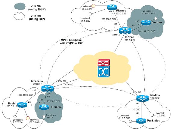
Este diagrama muestra una configuración típica que ilustra estas convenciones:
Antecedentes
Descripción
Hemos configurado una estructura básica MPLS ATM estándar con el área 0 Open Shortest Path First (OSPF) como protocolo de gateway interior (IGP). Hemos configurado dos VPN diferentes con esta estructura básica. El primero de ellos utiliza RIP como su protocolo de routing de borde del cliente a extremo del proveedor (CE-PE) y el otro utiliza BGP como su protocolo de routing PE-CE.
Hemos configurado varios loops de retorno y rutas estáticas en los routers CE para simular la presencia de otros routers y de otras redes.
Procedimiento de configuración
Nota: Es obligatorio utilizar BGP como el IGP VPN entre los routers PE. Esto se debe a que el uso de comunidades extendidas BGP es la única manera de transportar información de ruteo para la VPN entre los routers PE.
Diagrama de la red
Procedimiento de configuración Parte I
La documentación del IOS de Cisco (redes privadas virtuales MPLS) también describe este procedimiento de configuración.
Asegúrese de que la ip cef esté habilitada. Si utiliza un Cisco 7500 Router, asegúrese de que ip cef distributed esté habilitado. En los PE, una vez que se ha configurado MPLS, siga estos pasos:
-
Cree un VRF para cada VPN conectada con el comando ip vrf <VPN routing/forwarding instance name>:
-
Especifique el discriminador de rutas adecuado usado para esa VPN. Esto se utiliza para extender la dirección IP de modo que pueda identificar la VPN a la que pertenece.
rd -
Configure las propiedades de importación y exportación para las comunidades ampliadas BGP. Se utilizan para filtrar el proceso de importación y exportación.
route-target [export|import|both]
-
-
Configure los detalles de reenvío para las respectivas interfaces con este comando:
ip vrf forwarding
Nota: Recuerde configurar la dirección IP después de hacerlo.
Según el protocolo de ruteo PE-CE que utilice, ahora debe hacer uno o más de los siguientes pasos:
-
Configure las rutas estáticas:
ip route vrf vrf-name prefix mask [next-hop-address] [interface {interface-number}] -
Configure el RIP con este comando:
address-family ipv4 vrfUna vez que haya realizado esta parte, escriba los comandos de configuración de RIP normal.
Nota: Esto sólo se aplica a las interfaces de reenvío para el VRF actual.
Nota: Debe redistribuir el BGP correcto en RIP. Al hacerlo, recuerde especificar también la métrica que se utiliza.
-
Declare la información del vecino BGP.
-
Configure el OSPF con el nuevo comando IOS:
router ospfvrf . Nota: Esto sólo se aplica a las interfaces de reenvío para el VRF actual.
Nota: Debe redistribuir el BGP correcto en OSPF. Al hacerlo, recuerde especificar también la métrica que se utiliza.
Nota: Una vez que se atribuye el proceso OSPF a un VRF, este número de proceso siempre se utiliza para este VRF en particular. Esto sucede incluso si no lo especifica en la línea de comando.
Procedimiento de configuración Parte II
Configure BGO entre los routers PE. Hay varias maneras de configurar BGP; una forma es utilizar el reflector de ruta o los métodos de confederación. El método utilizado aquí - configuración de vecino directo - es el más simple y el menos escalable.
-
Declare los diferentes vecinos.
-
Ingrese la familia de direcciones ipv4 vrf <nombre de instancia de ruteo/reenvío VPN> para cada VPN presente en este router PE. Realice uno o varios de estos pasos, según sea necesario:
-
Vuelva a distribuir la información de ruteo estático.
-
Vuelva a distribuir los datos de RIP Routing.
-
‘Vuelva a distribuir la información de ruteo de OSPF.’
-
Active BGP en la proximidad a los routers CE.
-
-
Ingrese el modo address-family vpnv4 y realice una de estas acciones:
-
Activar los vecinos.
-
Especifique que debe usarse la comunidad extendida. Esto es obligatorio.
-
Configuraciones
En la configuración de Alcalzaba, las líneas específicas de la VPN 101 se muestran en negrita, las específicas de la VPN 102 se muestran en cursiva y las específicas de ambas se muestran en negrita y en cursiva.
Alcazaba ! ip vrf vrf101 rd 1:101 route-target export 1:101 route-target import 1:101 ! ip vrf vrf102 rd 1:102 route-target export 1:102 route-target import 1:102 ! ip cef ! interface Loopback0 ip address 223.0.0.3 255.255.255.255 ! interface Ethernet1/0 ip vrf forwarding vrf102 ip address 10.200.10.3 255.255.252.0 ! interface Ethernet1/1 ip vrf forwarding vrf101 ip address 150.150.0.1 255.255.255.0 ! interface ATM3/0 no ip address no ip mroute-cache no atm ilmi-keepalive pvc qsaal 0/5 qsaal pvc ilmi 0/16 ilmi ! ! interface ATM3/0.1 tag-switching ip address 10.0.0.17 255.255.255.252 tag-switching atm vpi 2-4 tag-switching ip ! interface ATM4/0 no ip address no atm ilmi-keepalive ! interface ATM4/0.1 tag-switching ip address 10.0.0.13 255.255.255.252 tag-switching atm vpi 2-4 tag-switching ip ! router ospf 1 network 10.0.0.0 0.0.0.255 area 0 network 223.0.0.3 0.0.0.0 area 0 ! router rip version 2 ! address-family ipv4 vrf vrf101 version 2 redistribute bgp 1 metric 0 network 150.150.0.0 no auto-summary exit-address-family ! router bgp 1 no synchronization neighbor 125.2.2.2 remote-as 1 neighbor 125.2.2.2 update-source Loopback0 neighbor 223.0.0.21 remote-as 1 neighbor 223.0.0.21 update-source Loopback0 no auto-summary ! address-family ipv4 vrf vrf102 redistribute connected neighbor 10.200.10.14 remote-as 158 neighbor 10.200.10.14 activate no auto-summary no synchronization exit-address-family ! address-family ipv4 vrf vrf101 redistribute rip no auto-summary no synchronization exit-address-family ! address-family vpnv4 neighbor 125.2.2.2 activate neighbor 125.2.2.2 send-community extended neighbor 223.0.0.21 activate neighbor 223.0.0.21 send-community extended no auto-summary exit-address-family !
Kozel ! ip vrf vrf101 rd 1:101 route-target export 1:101 route-target import 1:101 ! ip vrf vrf102 rd 1:102 route-target export 1:102 route-target import 1:102 ! ip cef ! interface Loopback0 ip address 223.0.0.21 255.255.255.255 ! interface Ethernet1/1 ip vrf forwarding vrf101 ip address 200.200.0.1 255.255.255.0 ! interface Ethernet1/2 ip vrf forwarding vrf102 ip address 201.201.201.1 255.255.255.252 ! interface ATM4/0 no ip address no atm scrambling cell-payload no atm ilmi-keepalive pvc qsaal 0/5 qsaal pvc ilmi 0/16 ilmi ! interface ATM4/0.1 tag-switching ip address 10.0.0.6 255.255.255.252 tag-switching atm vpi 2-4 tag-switching ip ! router ospf 1 log-adjacency-changes network 10.0.0.0 0.0.0.255 area 0 network 223.0.0.21 0.0.0.0 area 0 ! router rip version 2 ! address-family ipv4 vrf vrf101 version 2 redistribute bgp 1 metric 1 network 200.200.0.0 no auto-summary exit-address-family ! router bgp 1 no synchronization neighbor 125.2.2.2 remote-as 1 neighbor 125.2.2.2 update-source Loopback0 neighbor 223.0.0.3 remote-as 1 neighbor 223.0.0.3 update-source Loopback0 no auto-summary ! address-family ipv4 vrf vrf102 redistribute connected redistribute static neighbor 201.201.201.2 remote-as 69 neighbor 201.201.201.2 activate no auto-summary no synchronization exit-address-family ! address-family ipv4 vrf vrf101 redistribute rip no auto-summary no synchronization exit-address-family ! address-family vpnv4 neighbor 125.2.2.2 activate neighbor 125.2.2.2 send-community extended neighbor 223.0.0.3 activate neighbor 223.0.0.3 send-community extended no auto-summary exit-address-family !
Medina Current configuration: ! ip vrf vrf101 rd 1:101 route-target export 1:101 route-target import 1:101 ip cef ! interface Loopback1 ip vrf forwarding vrf101 ip address 11.2.2.2 255.255.255.252 ! interface ATM2/0 no ip address no atm ilmi-keepalive ! interface ATM2/0.66 tag-switching ip address 125.1.4.2 255.255.255.252 tag-switching ip ! interface Ethernet1/1 ip vrf forwarding vrf101 ip address 11.3.3.1 255.255.255.252 ! router ospf 1 network 125.1.4.0 0.0.0.3 area 0 network 125.2.2.2 0.0.0.0 area 0 ! router rip version 2 network 11.0.0.0 ! address-family ipv4 vrf vrf101 version 2 redistribute bgp 1 metric 1 network 11.0.0.0 no auto-summary exit-address-family ! router bgp 1 no synchronization neighbor 223.0.0.3 remote-as 1 neighbor 223.0.0.3 update-source Loopback0 neighbor 223.0.0.21 remote-as 1 neighbor 223.0.0.21 update-source Loopback0 ! address-family ipv4 vrf vrf101 redistribute connected redistribute static redistribute rip default-information originate no auto-summary no synchronization exit-address-family ! address-family vpnv4 neighbor 223.0.0.3 activate neighbor 223.0.0.3 send-community extended neighbor 223.0.0.21 activate neighbor 223.0.0.21 send-community extended exit-address-family !
Rápido Current configuration: ! interface Loopback0 ip address 223.0.0.12 255.255.255.255 ! interface Loopback2 ip address 7.7.7.7 255.255.255.0 ! interface FastEthernet0/1 ip address 150.150.0.2 255.255.255.0 duplex auto speed auto ! router rip version 2 redistribute static network 7.0.0.0 network 10.0.0.0 network 150.150.0.0 no auto-summary ! ip route 158.0.0.0 255.0.0.0 Null !
Damme ! interface Loopback1 ip address 6.6.6.6 255.0.0.0 ! interface FastEthernet0/0 ip address 10.200.10.14 255.255.252.0 duplex auto speed autoa ! router bgp 158 no synchronization network 6.0.0.0 network 10.200.0.0 mask 255.255.252.0 neighbor 10.200.10.3 remote-as 1 no auto-summary !
Pivrnec Current configuration: ! interface Loopback0 ip address 223.0.0.22 255.255.255.255 ! interface Loopback1 ip address 6.6.6.6 255.255.255.255 ! interface FastEthernet0/1 ip address 200.200.0.2 255.255.255.0 duplex auto speed auto ! router rip version 2 redistribute static network 6.0.0.0 network 200.200.0.0 no auto-summary ! ip route 69.0.0.0 255.0.0.0 Null0 !
Guilder ! interface Loopback2 ip address 150.150.0.1 255.255.0.0 ! interface Ethernet0/2 ip address 201.201.201.2 255.255.255.252 ! router bgp 69 no synchronization network 7.7.7.0 mask 255.255.0.0 network 150.150.0.0 network 201.201.201.0 mask 255.255.255.252 redistribute connected neighbor 201.201.201.1 remote-as 1 no auto-summary !
Purkmister Current configuration: ! interface Loopback0 ip address 11.5.5.5 255.255.255.252 ! interface FastEthernet0/1 ip address 11.3.3.2 255.255.255.252 duplex auto speed auto ! router rip version 2 network 11.0.0.0 !
Comandos show
Comandos específicos de ruteo
La herramienta Output Interpreter Tool (clientes registrados solamente) (OIT) soporta ciertos comandos show. Utilice la OIT para ver un análisis del resultado del comando show.
-
show ip rip database vrf
-
show ip bgp vpnv4 vrf
-
show ip route vrf
-
show ip route
En un router PE, el método de ruteo PE-CE (como RIP, BGP o static) y las actualizaciones BGP PE-PE indican la tabla de ruteo que se utiliza para un VRF determinado. Puede mostrar la información RIP para un VRF determinado:
Alcazaba#show ip rip database vrf vrf101
 0.0.0.0/0 auto-summary
 0.0.0.0/0
 [2] via 150.150.0.2, 00:00:12, Ethernet1/1
 6.0.0.0/8 auto-summary
 6.6.6.6/32 redistributed
 [1] via 223.0.0.21,
 7.0.0.0/8 auto-summary
 7.7.7.0/24
 [1] via 150.150.0.2, 00:00:12, Ethernet1/1
 10.0.0.0/8 auto-summary
 10.0.0.0/8 redistributed
 [1] via 125.2.2.2,
 10.0.0.0/16
 [1] via 150.150.0.2, 00:00:12, Ethernet1/1
 10.200.8.0/22
 [1] via 150.150.0.2, 00:00:12, Ethernet1/1
 11.0.0.0/8 auto-summary
 11.0.0.4/30 redistributed
 [1] via 125.2.2.2,
 11.1.1.0/30 redistributed
 [1] via 125.2.2.2,
 11.3.3.0/30 redistributed
 [1] via 125.2.2.2,
 11.5.5.4/30 redistributed
 [1] via 125.2.2.2,
 69.0.0.0/8 auto-summary
 69.0.0.0/8 redistributed
 [1] via 223.0.0.21,
 150.150.0.0/16 auto-summary
 150.150.0.0/24 directly connected, Ethernet1/1
 158.0.0.0/8
 [1] via 150.150.0.2, 00:00:17, Ethernet1/1
 200.200.0.0/24 auto-summary
 200.200.0.0/24 redistributed
 [1] via 223.0.0.21,
También puede mostrar la información de BGP para un VRF determinado con el comando show ip bgp vpnv4 vrf. Los resultados PE-PE del BGP interno (IBGP) están indicados con una i.
Alcazaba#show ip bgp vpnv4 vrf vrf101
   BGP table version is 46, local router ID is 223.0.0.3
   Status codes: s suppressed, d damped, h history, * valid, best, i - internal
   Origin codes: i - IGP, e - EGP, ? - incomplete

 Network Next Hop Metric LocPrf Weight Path
   Route Distinguisher: 1:101 (default for vrf vrf101)
   *i6.6.6.6/32 223.0.0.21 1 100 0 ?
   * 7.7.7.0/24 150.150.0.2 1 32768 ?
   * 10.0.0.0/16 150.150.0.2 1 32768 ?
   * 10.200.8.0/22 150.150.0.2 1 32768 ?
   *i11.2.2.0/30 125.2.2.2 0 100 0 ?
   *i11.3.3.0/30 125.2.2.2 0 100 0 ?
   *i11.5.5.4/30 125.2.2.2 1 100 0 ?
   *i69.0.0.0 223.0.0.21 1 100 0 ?
   * 150.150.0.0/24 0.0.0.0 0 32768 ?
   * 158.0.0.0/8 150.150.0.2 1 32768 ?
   *i200.200.0.0 223.0.0.21 0 100 0 ?

Kozel#show ip bgp vpnv4 vrf vrf102
BGP table version is 48, local router ID is 223.0.0.21
Status codes: s suppressed, d damped, h history, * valid, > best, i - internal
Origin codes: i - IGP, e - EGP, ? - incomplete

   Network          Next Hop            Metric LocPrf Weight Path
Route Distinguisher: 1:102 (default for vrf vrf102)
* i6.0.0.0          223.0.0.3                0    100      0 158 i
*>i                 223.0.0.3                0    100      0 158 i
*> 7.7.0.0/16       201.201.201.2            0             0 69 ?
*  10.200.8.0/22    201.201.201.2            0             0 69 ?
* i                 223.0.0.3                0    100      0 ?
*>i                 223.0.0.3                0    100      0 ?
*> 102.102.0.0/16   201.201.201.2            0             0 69 ?
*> 150.150.0.0      201.201.201.2            0             0 69 i
*  201.201.201.0/30 201.201.201.2            0             0 69 i
*>                  0.0.0.0                  0         32768 ?
Puede buscar un VRF en la tabla de ruteo global en routers CE y PE. Estos partidos. Para el router PE, debe especificar el VRF con el comando show ip route vrf .
Alcazaba#show ip route vrf vrf101
   Codes: C - connected, S - static, I - IGRP, R - RIP, M - mobile, B - BGP
   D - EIGRP, EX - EIGRP external, O - OSPF, IA - OSPF inter area
   N1 - OSPF NSSA external type 1, N2 - OSPF NSSA external type 2
   E1 - OSPF external type 1, E2 - OSPF external type 2, E - EGP
   i - IS-IS, L1 - IS-IS level-1, L2 - IS-IS level-2, ia - IS-IS inter area
   * - candidate default, U - per-user static route, o - ODR
   P - periodic downloaded static route
    Gateway of last resort is not set
   B 69.0.0.0/8 [200/1] via 223.0.0.21, 00:11:03
   B 200.200.0.0/24 [200/0] via 223.0.0.21, 00:11:03
    6.0.0.0/32 is subnetted, 1 subnets
   B 6.6.6.6 [200/1] via 223.0.0.21, 00:11:03
    7.0.0.0/24 is subnetted, 1 subnets
   R 7.7.7.0 [120/1] via 150.150.0.2, 00:00:05, Ethernet1/1
    10.0.0.0/8 is variably subnetted, 2 subnets, 2 masks
   R 10.0.0.0/16 [120/1] via 150.150.0.2, 00:00:05, Ethernet1/1
   R 10.200.8.0/22 [120/1] via 150.150.0.2, 00:00:05, Ethernet1/1
    11.0.0.0/30 is subnetted, 3 subnets
   B 11.3.3.0 [200/0] via 125.2.2.2, 00:07:05
   B 11.2.2.0 [200/0] via 125.2.2.2, 00:07:05
   B 11.5.5.4 [200/1] via 125.2.2.2, 00:07:05
    150.150.0.0/24 is subnetted, 1 subnets
   C 150.150.0.0 is directly connected, Ethernet1/1
   R 158.0.0.0/8 [120/1] via 150.150.0.2, 00:00:06, Ethernet1/1
Para Pivrnec, ésta es la tabla de ruteo estándar, así que utilice el comando show ip route:
Pivrnec#show ip route
Codes: C - connected, S - static, I - IGRP, R - RIP, M - mobile, B - BGP
  D - EIGRP, EX - EIGRP external, O - OSPF, IA - OSPF inter area
  N1 - OSPF NSSA external type 1, N2 - OSPF NSSA external type 2
  E1 - OSPF external type 1, E2 - OSPF external type 2, E - EGP
  i - IS-IS, L1 - IS-IS level-1, L2 - IS-IS level-2, ia - IS-IS inter area
  * - candidate default, U - per-user static route, o - ODR
  P - periodic downloaded static route Gateway of last resort is not  set S 69.0.0.0/8 is directly connected, Null0
  223.0.0.0/32 is subnetted, 1 subnets
 C 223.0.0.22 is directly connected, Loopback0
 C 200.200.0.0/24 is directly connected, FastEthernet0/1
  6.0.0.0/32 is subnetted, 1 subnets
 C 6.6.6.6 is directly connected, Loopback1
  7.0.0.0/24 is subnetted, 1 subnets
 R 7.7.7.0 [120/1] via 200.200.0.1, 00:00:23, FastEthernet0/1
  10.0.0.0/8 is variably subnetted, 2 subnets, 2 masks
 R 10.0.0.0/16 [120/1] via 200.200.0.1, 00:00:23, FastEthernet0/1
 R 10.200.8.0/22 [120/1] via 200.200.0.1, 00:00:24, FastEthernet0/1
  11.0.0.0/30 is subnetted, 3 subnets
 R 11.3.3.0 [120/1] via 200.200.0.1, 00:00:24, FastEthernet0/1
 R 11.2.2.0 [120/1] via 200.200.0.1, 00:00:25, FastEthernet0/1
 R 11.5.5.4 [120/1] via 200.200.0.1, 00:00:25, FastEthernet0/1
  150.150.0.0/24 is subnetted, 1 subnets
 R 150.150.0.0 [120/1] via 200.200.0.1, 00:00:25, FastEthernet0/1
 R 158.0.0.0/8 [120/1] via 200.200.0.1, 00:00:25, FastEthernet0/1
Etiquetas MPLS
Verifique la pila de etiquetas utilizada para cualquier ruta en particular:
 Alcazaba#show tag-switching forwarding-table vrf vrf101 11.5.5.5 detail
   Local Outgoing Prefix Bytes tag Outgoing Next Hop
   tag tag or VC or Tunnel Id switched interface
   None 2/91 11.5.5.4/30 0 AT4/0.1 point2point
    MAC/Encaps=4/12, MTU=4466, Tag Stack{2/91(vcd=69) 37}
    00458847 0004500000025000
También puede utilizar los comandos normales para ver las asignaciones de etiquetas y las relaciones VPI/VCI aquí.
Superposición de direcciones
La misma dirección se puede utilizar en diferentes VPNs sin interferencia con las otras. En este ejemplo, la dirección 6.6.6.6 está conectada dos veces, a Pivrnec en VPN 101 y a Damme en VPN 102. Podemos verificar esto con ping en un sitio y debug ip icmp en el otro sitio.
Guilder#ping 6.6.6.6
   Type escape sequence to abort.
   Sending 5, 100-byte ICMP Echos to 6.6.6.6, timeout is 2 seconds:
   !!!!!
   Success rate is 100 percent (5/5), round-trip min/avg/max = 4/4/4 ms

Damme#debug ip icmp
   ICMP packet debugging is on
   6d22h: ICMP: echo reply sent, src 6.6.6.6, dst 201.201.201.2
   6d22h: ICMP: echo reply sent, src 6.6.6.6, dst 201.201.201.2
   6d22h: ICMP: echo reply sent, src 6.6.6.6, dst 201.201.201.2
   6d22h: ICMP: echo reply sent, src 6.6.6.6, dst 201.201.201.2
   6d22h: ICMP: echo reply sent, src 6.6.6.6, dst 201.201.201.2
Ejemplo de resultado del comando debug
El resultado de ejemplo que utiliza la misma configuración está disponible aquí.
Información Relacionada
Historial de revisiones
| Revisión | Fecha de publicación | Comentarios |
|---|---|---|
1.0 |
16-Nov-2005 |
Versión inicial |
 Comentarios
Contacte a Cisco
- Abrir un caso de soporte

- (Requiere un Cisco Service Contract)