- Preface
- Chapter 1 - Overview
- Chapter 2 - Preparing for Installation
- Chapter 3 - Installing and Configuring the Client Adapter
- Chapter 4 - Enabling Security Features
- Chapter 5 - Advanced Configuration
- Chapter 6 - Performing Diagnostics
- Chapter 7 - Routine Procedures
- Chapter 8 - Troubleshooting
- Appendix A - Technical Specifications
- Appendix B - Channels
- Appendix C - Translated Safety Warnings
- Appendix D - Declarations of Conformity and Regulatory Information
- Glossary
Cisco Aironet Wireless LAN Adapters Installation and Configuration Guide for Linux
Bias-Free Language
The documentation set for this product strives to use bias-free language. For the purposes of this documentation set, bias-free is defined as language that does not imply discrimination based on age, disability, gender, racial identity, ethnic identity, sexual orientation, socioeconomic status, and intersectionality. Exceptions may be present in the documentation due to language that is hardcoded in the user interfaces of the product software, language used based on RFP documentation, or language that is used by a referenced third-party product. Learn more about how Cisco is using Inclusive Language.
- Updated:
- May 4, 2007
Chapter: Chapter 5 - Advanced Configuration
Advanced Configuration
This chapter provides a comprehensive list of the client adapter's advanced configuration parameters, defaults, and ranges. The chapter also provides instructions on how to configure the client adapter in a home network.
The following topics are covered in this chapter.
•![]() Setting Enterprise Parameters
Setting Enterprise Parameters
•![]() Setting Network Security Parameters
Setting Network Security Parameters
•![]() Setting RF Network Parameters
Setting RF Network Parameters
•![]() Setting Home Networking Parameters
Setting Home Networking Parameters
•![]() Setting Advanced Infrastructure Parameters
Setting Advanced Infrastructure Parameters
•![]() Setting Advanced Ad Hoc Parameters
Setting Advanced Ad Hoc Parameters
Overview
The ACU enables you to change the configuration parameters of your client adapter. The adapter's parameters are organized into two main categories depending on your network's configuration:
•![]() Enterprise parameters—Use these parameters to configure your client adapter for use in an enterprise network, such as that found in a large organization:
Enterprise parameters—Use these parameters to configure your client adapter for use in an enterprise network, such as that found in a large organization:
–![]() System parameters—Prepare the client adapter for use in a wireless network
System parameters—Prepare the client adapter for use in a wireless network
–![]() Network security parameters—Control the level of security provided to your wireless network
Network security parameters—Control the level of security provided to your wireless network

Note ![]() See "Enabling Security Features," for instructions on setting network security parameters.
See "Enabling Security Features," for instructions on setting network security parameters.
–![]() RF network parameters—Control how the client adapter transmits and receives data
RF network parameters—Control how the client adapter transmits and receives data
–![]() Advanced infrastructure parameters—Control how the client adapter operates within an infrastructure network
Advanced infrastructure parameters—Control how the client adapter operates within an infrastructure network
–![]() Advanced ad hoc parameters—Control how the client adapter operates within an ad hoc (peer-to-peer) network
Advanced ad hoc parameters—Control how the client adapter operates within an ad hoc (peer-to-peer) network
•![]() Home networking parameters—Use these parameters to prepare your client adapter to operate in a home network.
Home networking parameters—Use these parameters to prepare your client adapter to operate in a home network.
Note ![]() Despite their name, the home networking parameters are not limited to use in a home network. For instance, these parameters, which are confined to one screen, provide a convenient way to minimally configure the client adapter.
Despite their name, the home networking parameters are not limited to use in a home network. For instance, these parameters, which are confined to one screen, provide a convenient way to minimally configure the client adapter.
Table 5-1 enables you to quickly locate the instructions for modifying the client adapter's parameters.
|
|
|
|---|---|
Enterprise |
|
System |
|
Network security |
|
RF network |
|
Advanced infrastructure |
|
Advanced ad hoc |
|
Home networking |
Setting Enterprise Parameters
The parameters in this section can be used to configure your client adapter for use in an enterprise network. If you are planning to use your client adapter in a home network, go to the "Specifying a Home Network Configuration" section.
Setting System Parameters
The System Parameters screen (Figure 5-1) enables you to set parameters that prepare the client adapter for use in a wireless network. To access this screen, select Edit Properties from the Commands pull-down menu and click the System Parameters tab.
Figure 5-1 Systems Parameters Screen
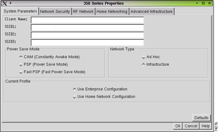
Table 5-2 lists and describes the client adapter's system parameters. Follow the instructions in the table to initially set or change any parameters.
Click OK at the bottom of the System Parameters screen to save any changes.
Setting Network Security Parameters
The Network Security screen (see Figure 5-2) enables you to set parameters that offer varying degrees of security for the data that is passed throughout your wireless network. To access this screen, select Edit Properties from the Commands pull-down menu, and click the Network Security tab.
Figure 5-2 Network Security Screen
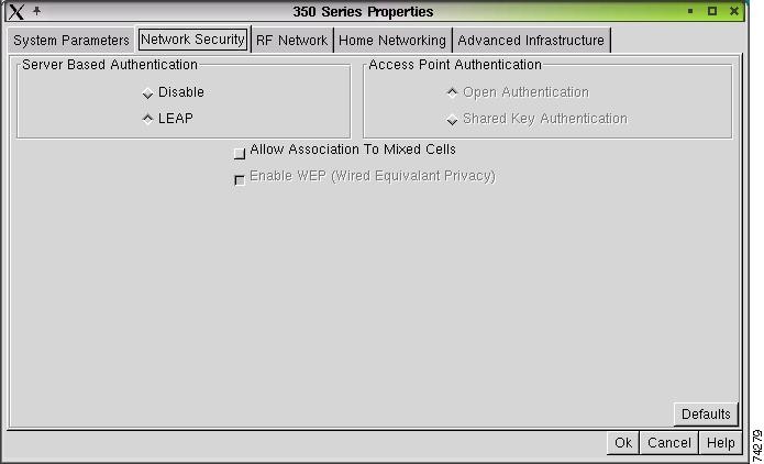
Table 5-3 lists and describes the client adapter's network security parameters. Follow the instructions in the table to initially set or to change any parameters
Note ![]() See "Enabling Security Features," for instructions on setting network security parameters.
See "Enabling Security Features," for instructions on setting network security parameters.
|
|
|
|
|---|---|---|
Server Based Authentication |
Disables or enables LEAP (also referred to as EAP - Cisco Wireless) for your client adapter after LEAP is enabled initially through the Set LEAP Username and Password screen). Note |
|
Server Based Authentication Option |
|
|
None |
Disables LEAP for your client adapter. |
|
LEAP |
Enables LEAP for your client adapter. Note |
|
Access Point Authentication |
Defines how your client adapter attempts to authenticate to an access point. |
|
Authentication |
Description |
|
Open Authentication |
Allows your client adapter, regardless of its WEP settings, to authenticate and attempt to communicate with an access point. |
|
Shared Key Authentication |
Allows your client adapter to communicate only with access points that have the same WEP keys. The access point sends a known unencrypted challenge packet to the client adapter, which encrypts the packet and sends it back to the access point. The access point attempts to decrypt the encrypted packet and sends back to the client adapter an authentication-response packet that shows the success or the failure of the decryption. |
|
Note Note |
||
Allow Association To |
If your network's access points are set to communicate with either WEP-enabled or WEP-disabled clients (that is, if the Use of Data Encryption by Stations parameter on the AP Radio Data Encryption screen is set to Optional), you must select this check box in order to associate using WEP. If this setting is not enabled, your client adapter cannot establish a connection with the access point. Note Note |
|
Enable WEP (Wired Equivalent Privacy) |
Enables or disables WEP for your client adapter. This parameter can be used in two ways: • • Note |
|
Click OK at the bottom of the Network Security Parameters screen to save any changes.
Setting RF Network Parameters
The RF Network screen (see Figure 5-3) enables you to set parameters that control how and when the client adapter transmits and receives data. To access this screen, select Edit Properties from the Commands pull-down menu and click the RF Network tab.
Figure 5-3 RF Network Parameters Screen
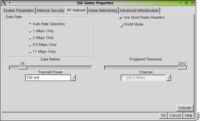
Table 5-4 lists and describes the client adapter's RF network parameters. Follow the instructions in the table to initially set or to change any parameters.
|
|
|
|
|---|---|---|
Data Rate |
Specifies the rate at which you want your client adapter to transmit or receive packets to or from access points (in infrastructure mode) or other clients (in ad hoc mode). We recommend Auto Rate Selection for infrastructure mode; setting a specific data rate is recommended for ad hoc mode. |
|
Data Rate |
Description |
|
Auto Rate Selection |
Uses the 11-Mbps data rate when possible but drops to lower rates when necessary. |
|
1 Mbps Only |
Offers the greatest range but the lowest throughput. |
|
2 Mbps Only |
Offers less range but greater throughput than the 1 Mbps Only option. |
|
5.5 Mbps Only |
Offers less range but greater throughput than the 2 Mbps Only option. |
|
11 Mbps Only |
Offers the greatest throughput but the lowest range. |
|
Note |
||
Use Short Radio Headers |
Selecting this check box sets your client adapter to use short radio headers. However, the adapter uses short radio headers regardless of how the access point is configured. Short radio headers improve throughput performance; long radio headers ensure compatibility with clients and access points that do not support short radio headers. |
|
World Mode |
Selecting this check box enables the client adapter to assume the legal transmit power level and channel set of the access point to which it is associated. This parameter is available only in infrastructure mode and is designed for users who travel between countries because it allows the adapter to be used in different regulatory domains. Note |
|
Channel |
Specifies which frequency your client adapter uses as the channel for communications. These channels conform to the IEEE 802.11 standard for your regulatory domain. • • Example: 1 to 11 (2412 to 2462 MHz) in North America. Example: 6 (2437 MHz) in North America. Note |
|
Transmit Power |
Defines the level at which your client adapter transmits power. This value must not be higher than that allowed by your country's regulatory agency (FCC in the U.S., DOC in Canada, ETSI in Europe, MKK in Japan, and so on). When World Mode is enabled, only the transmit power levels supported by the country of operation's regulatory agency are available. Note Note |
|
Data Retries |
Defines the number of times a packet is resent if the initial transmission is unsuccessful. Note |
|
Fragment Threshold |
Defines the threshold above which an RF data packet is split up or fragmented. If one of those fragmented packets experiences interference during transmission, only that specific packet needs to be resent. Throughput is generally lower for fragmented packets because the fixed packet overhead consumes a higher portion of the RF bandwidth. Note |
|
Click OK at the bottom of the RF Network screen to save any changes.
Setting Home Networking Parameters
The parameters in this section configure your client adapter for use in a home (non-enterprise) network. If you are planning to use your client adapter in an enterprise network, go to the "Setting Enterprise Parameters" section.
The Home Networking screen (see Figure 5-4) enables you to set parameters that prepare the client adapter to operate in a home network. To access this screen, select Edit Properties from the Commands pull-down menu and click the Home Networking tab.
Figure 5-4 Home Networking Parameters Screen
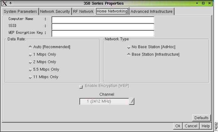
Table 5-5 lists and describes the client adapter's home networking parameters. Follow the instructions in the table to initially set or to change any parameters.
Click OK at the bottom of the Home Networking Parameters screen to save any changes.
|
|
|
|
|---|---|---|
Computer Name |
The client name for the home network. It is a logical name for your workstation. It enables you to determine which devices are connected to the base station (the home equivalent of an access point) without having to memorize every MAC address. This name is included in the base station's list of connected devices. Note |
|
SSID |
The service set identifier (SSID) enables you to access the home network. Note |
|
WEP Encryption Key |
The WEP key for the home network. See the "WEP" section for information on WEP keys. Note |
|
Enable Encryption (WEP) |
Selecting this check box enables WEP for your client adapter. This check box is inaccessible until you set an encryption key by using the WEP Encryption Key parameter. Note |
|
Data Rate |
Specifies the rate at which your client adapter transmits or receives packets to or from other devices on the home network. |
|
Data Rate |
Description |
|
Auto |
Uses the 11-Mbps data rate when possible but drops to lower rates when necessary. |
|
1 Mbps Only |
Offers the greatest range but the lowest throughput. |
|
2 Mbps Only |
Offers less range but greater throughput than the 1 Mbps Only option. |
|
5.5 Mbps Only |
Offers less range but greater throughput than the 2 Mbps Only option. |
|
11 Mbps Only |
Offers the greatest throughput but the lowest range. |
|
Note Note |
||
Network Type |
Specifies the type of network in which your client adapter is installed. |
|
Network Type |
Description |
|
No Base Station |
Also referred to as peer to peer. Used to set up a small network between two or more devices. For example, a network without a base station could be set up between computers in a room so that information can be shared. |
|
Base Station (Infrastructure) |
Used to set up a connection to a wired Ethernet network (through a base station). |
|
Channel |
Specifies which frequency your client adapter uses as the channel for communications. These channels conform to the IEEE 802.11 standard for your regulatory domain. • • Example: 1 to 11 (2412 to 2462 MHz) in North America. Example: 6 (2437 MHz) in North America. Note |
|
Go to the "Specifying a Home Network Configuration" section for instructions on activating a home network configuration.
Specifying a Home Network Configuration
After you have set the parameters to prepare your client adapter for use in a home network, you must specify a home network configuration. To do so, follow these instructions.
Step 1 ![]() Select Edit Properties from the Commands pull-down menu, and click the System Parameters tab. The System Parameters screen appears (see Figure 5-1).
Select Edit Properties from the Commands pull-down menu, and click the System Parameters tab. The System Parameters screen appears (see Figure 5-1).
Step 2 ![]() Select Use Home Network Configuration under Current Profile or Default Profile.
Select Use Home Network Configuration under Current Profile or Default Profile.
Step 3 ![]() Click OK to save this setting.
Click OK to save this setting.
Setting Advanced Infrastructure Parameters
Note ![]() You can set advanced infrastructure parameters only if your client adapter is set to operate in an infrastructure network. See the Network Type parameter in Table 5-2.
You can set advanced infrastructure parameters only if your client adapter is set to operate in an infrastructure network. See the Network Type parameter in Table 5-2.
The Advanced Infrastructure screen (see Figure 5-5) enables you to set parameters that control how the client adapter operates within an infrastructure network. To access this screen, select Edit Properties from the Commands pull-down menu, and click the Advanced Infrastructure tab.
Figure 5-5 Advanced Infrastructure Parameters Screen
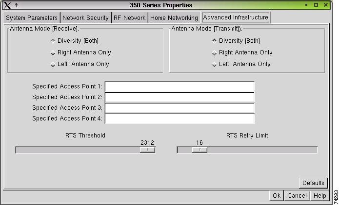
Table 5-6 lists and describes the client adapter's advanced infrastructure parameters. Follow the instructions in the table to initially set or to change any parameters.
Click OK at the bottom of the Advanced (Infrastructure) screen to save any changes.
Setting Advanced Ad Hoc Parameters
Note ![]() You can set advanced ad hoc parameters only if your client adapter is set to operate in an ad hoc network. See the Network Type parameter in Table 5-2.
You can set advanced ad hoc parameters only if your client adapter is set to operate in an ad hoc network. See the Network Type parameter in Table 5-2.
The Advanced Ad Hoc screen (see Figure 5-6) enables you to set parameters that control how the client adapter operates within an ad hoc network. To access this screen, select Edit Properties from the Commands pull-down menu, and click the Advanced Ad Hoc tab.
Figure 5-6 Advanced Ad Hoc Parameters Screen
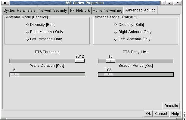
Table 5-7 lists and describes the client adapter's advanced ad hoc parameters. Follow the instructions in the table to initially set or change any parameters.
Click OK at the bottom of the Advanced (Ad Hoc) screen to save any changes.
 Feedback