- Preface
- Chapter 1 - Overview
- Chapter 2 - Preparing for Installation
- Chapter 3 - Installing and Configuring the Client Adapter
- Chapter 4 - Enabling Security Features
- Chapter 5 - Advanced Configuration
- Chapter 6 - Performing Diagnostics
- Chapter 7 - Routine Procedures
- Chapter 8 - Troubleshooting
- Appendix A - Technical Specifications
- Appendix B - Channels
- Appendix C - Translated Safety Warnings
- Appendix D - Declarations of Conformity and Regulatory Information
- Glossary
Cisco Aironet Wireless LAN Adapters Installation and Configuration Guide for Linux
Bias-Free Language
The documentation set for this product strives to use bias-free language. For the purposes of this documentation set, bias-free is defined as language that does not imply discrimination based on age, disability, gender, racial identity, ethnic identity, sexual orientation, socioeconomic status, and intersectionality. Exceptions may be present in the documentation due to language that is hardcoded in the user interfaces of the product software, language used based on RFP documentation, or language that is used by a referenced third-party product. Learn more about how Cisco is using Inclusive Language.
- Updated:
- May 4, 2007
Chapter: Chapter 1 - Overview
Overview
This chapter describes the Cisco Aironet Wireless LAN Adapters, also referred to as client adapters, and illustrates their roles in a wireless network.
The following topics are covered in this section:
•![]() Introduction to the Client Adapters
Introduction to the Client Adapters
•![]() Introduction to the Software Components
Introduction to the Software Components
•![]() Network Configurations Using the Client Adapter
Network Configurations Using the Client Adapter
•![]() Positioning Your Wireless Products
Positioning Your Wireless Products
Introduction to the Client Adapters
The Cisco Aironet Wireless LAN Adapters, also referred to as client adapters, are radio modules that provide transparent, wireless, data communications between fixed, portable, or mobile devices and other wireless devices or a wired network infrastructure. The client adapters are fully compatible when used in devices supporting Plug-and-Play (PnP) technology.
The primary function of the client adapters is to transfer data packets transparently through the wireless infrastructure. The adapters operate similarly to a standard network product except that the cable is replaced with a radio connection. No special wireless networking functions are required, and all existing applications that operate over a network will operate using the adapters.
This document covers four types of client adapters:


Refer to the "Radio Antenna" section for antenna differences between these adapters.
Terminology
Throughout this document, the following terms are used:
•![]() client adapter—Refers to all five types of adapters
client adapter—Refers to all five types of adapters
•![]() PC card, LM card, PCI client adapter, or PCI card—Refers only to a specific adapter
PC card, LM card, PCI client adapter, or PCI card—Refers only to a specific adapter
•![]() workstation (or station)—Refers to a computing device with an installed client adapter
workstation (or station)—Refers to a computing device with an installed client adapter
Parts of the Client Adapter
The client adapter is composed of three major parts: a radio, a radio antenna, and light-emitting diodes (LEDs).
Radio
The client adapter contains a direct-sequence spread spectrum (DSSS) radio that operates in the 2.4-GHz license-free Industrial Scientific Medical (ISM) band. The radio transmits data over a half-duplex radio channel operating at up to 11 Mbps.
DSSS technology causes radio signals to be transmitted over a wide frequency range, using multiple frequencies simultaneously. The benefit of this technology is its ability to protect the data transmission from interference. For example, if a particular frequency encounters noise, interference, or both, enough redundancy is built into the signal on other frequencies that the client adapter usually will still be successful in its transmission.
Radio Antenna
The type of antenna used depends on your client adapter:
•![]() PC cards have an integrated, permanently attached diversity antenna. The benefit of the diversity antenna system is improved coverage. The system works by allowing the card to switch and sample between its two antenna ports in order to select the optimum port for receiving data packets. As a result, the card has a better chance of maintaining the radio frequency (RF) connection in areas of interference. The antenna is housed within the section of the card that protrudes from the PC card slot when the card is installed.
PC cards have an integrated, permanently attached diversity antenna. The benefit of the diversity antenna system is improved coverage. The system works by allowing the card to switch and sample between its two antenna ports in order to select the optimum port for receiving data packets. As a result, the card has a better chance of maintaining the radio frequency (RF) connection in areas of interference. The antenna is housed within the section of the card that protrudes from the PC card slot when the card is installed.
•![]() LM cards are shipped without an antenna; however, an antenna can be connected through the card's external connector. If a snap-on antenna is used, it should be operated in diversity mode. Otherwise, the antenna mode used should correspond to the antenna port to which the antenna is connected.
LM cards are shipped without an antenna; however, an antenna can be connected through the card's external connector. If a snap-on antenna is used, it should be operated in diversity mode. Otherwise, the antenna mode used should correspond to the antenna port to which the antenna is connected.
•![]() PCI client adapters are shipped with a 2-dBi dipole antenna that attaches to the adapter's antenna connector. However, other types of antennas can be used. PCI client adapters can be operated only through the antenna port located on the right side of the radio module (not to be confused with the antenna connector on the card carrier).
PCI client adapters are shipped with a 2-dBi dipole antenna that attaches to the adapter's antenna connector. However, other types of antennas can be used. PCI client adapters can be operated only through the antenna port located on the right side of the radio module (not to be confused with the antenna connector on the card carrier).

Note ![]() See the "Setting Advanced Infrastructure Parameters" section for information on setting the client adapter's antenna mode.
See the "Setting Advanced Infrastructure Parameters" section for information on setting the client adapter's antenna mode.
Note ![]() External antennas used in combination with a power setting resulting in a radiated power level above 100 mW equivalent isotropic radiated power (EIRP) are not allowed for use within the European community and other countries that have adopted the European R&TTE directive or the CEPT recommendation Rec 70.03 or both. For more details on legal combinations of power levels and antennas in those countries, contact Cisco Corporate Compliance. See also the "Declaration of Conformity with Regard to the R&TTE Directive 1999/5/EC" section.
External antennas used in combination with a power setting resulting in a radiated power level above 100 mW equivalent isotropic radiated power (EIRP) are not allowed for use within the European community and other countries that have adopted the European R&TTE directive or the CEPT recommendation Rec 70.03 or both. For more details on legal combinations of power levels and antennas in those countries, contact Cisco Corporate Compliance. See also the "Declaration of Conformity with Regard to the R&TTE Directive 1999/5/EC" section.
LEDs
The client adapter has two LEDs that glow or blink to indicate the status of the adapter or to convey error messages. See Chapter 8, for an interpretation of the LED codes.
Introduction to the Software Components
The client adapter's software components consist of the following:
•![]() Firmware
Firmware
•![]() Driver
Driver
•![]() Client utilities
Client utilities
The installation program installs the client utilities and driver. Firmware is installed on the client adapter at the factory. You can update all the software components. Procedures for updating the firmware, drivers, and client utilities can be found in "Routine Procedures."
Cisco's Linux driver and client utilities support version 2.2.xx or 2.4.xx of the Linux kernel.
The following client utilities are available:
•![]() The Aironet Client Utility loads new firmware, configures the client adapter, enables security features, configures a WEP key, and performs user-level diagnostics.
The Aironet Client Utility loads new firmware, configures the client adapter, enables security features, configures a WEP key, and performs user-level diagnostics.
•![]() Three LEAP Credential Utilities provide a different interface for entering LEAP credentials:
Three LEAP Credential Utilities provide a different interface for entering LEAP credentials:
–![]() Leaplogin: An X window application for configuring LEAP credentials. A graphical dialogue box prompts you for your LEAP username and password.
Leaplogin: An X window application for configuring LEAP credentials. A graphical dialogue box prompts you for your LEAP username and password.
–![]() Leapset: An interactive command line utility for configuring LEAP credentials. This utility prompts you for your LEAP username and password.
Leapset: An interactive command line utility for configuring LEAP credentials. This utility prompts you for your LEAP username and password.
–![]() Leapscript: A non-interactive utility for configuring LEAP credentials designed for inclusion in shell scripts. (In the shell script, the LEAP password will be in clear text, so ensure that the permissions on the script are appropriate.)
Leapscript: A non-interactive utility for configuring LEAP credentials designed for inclusion in shell scripts. (In the shell script, the LEAP password will be in clear text, so ensure that the permissions on the script are appropriate.)
Note ![]() The LEAP username and password do not need to be the same as those for your Linux user account.
The LEAP username and password do not need to be the same as those for your Linux user account.
•![]() The Bcard Utility is an optional Linux-specific utility that reads a previously saved client adapter configuration, which was set in the Aironet Client Utilities (ACU). For a detailed description of Bcard, see "Using the Bcard Utility" section.
The Bcard Utility is an optional Linux-specific utility that reads a previously saved client adapter configuration, which was set in the Aironet Client Utilities (ACU). For a detailed description of Bcard, see "Using the Bcard Utility" section.
Network Configurations Using the Client Adapter
The client adapter can be used in a variety of network configurations. In some configurations, access points provide connections to your network or act as repeaters to increase wireless communication range. The maximum communication range is based on how you configure your wireless network.
This section describes and illustrates the following common network configurations:
•![]() Ad hoc wireless LAN
Ad hoc wireless LAN
•![]() Wireless infrastructure with workstations accessing a wired LAN
Wireless infrastructure with workstations accessing a wired LAN
Note ![]() For examples of more complex network configurations involving client adapters and access points, refer to the Cisco Aironet Access Point Hardware Installation Guide.
For examples of more complex network configurations involving client adapters and access points, refer to the Cisco Aironet Access Point Hardware Installation Guide.
Note ![]() See the "Configuring Your Client Adapter" section for information on setting the client adapter's network mode.
See the "Configuring Your Client Adapter" section for information on setting the client adapter's network mode.
Ad Hoc Wireless LAN
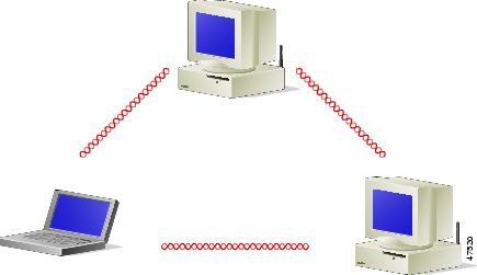
An ad hoc (or peer-to-peer) wireless LAN (see Figure 1-1) is the simplest wireless LAN configuration. In a wireless LAN using an ad hoc network configuration, all devices equipped with a client adapter can be linked together and communicate directly with each other.
Figure 1-1 Ad Hoc Wireless LAN
Wireless Infrastructure with Workstations Accessing a Wired LAN
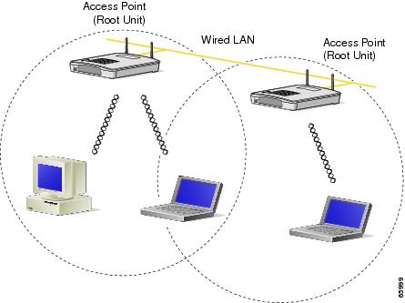
A microcellular network can be created by placing two or more access points on a LAN. Figure 1-2 shows a microcellular network with workstations accessing a wired LAN through several access points.
This configuration is useful with portable or mobile stations because it allows them to be directly connected to the wired network even while moving from one microcell domain to another. This process is transparent, and the connection to the file server or host is maintained without disruption. The mobile station stays connected to an access point as long as it can. However, once the transfer of data packets needs to be retried or beacons are missed, the station automatically searches for and associates to another access point. This process is referred to as seamless roaming.
Figure 1-2 Wireless Infrastructure with Workstations Accessing a Wired LAN
Positioning Your Wireless Products
Determining the network location of your wireless products can be influenced by a number of factors. This section discusses those factors and provides guidelines and tools for achieving optimum placement.
The site survey and link test tools provided with the client utilities can help you to determine the best placement for access points and workstations within your wireless network. See the "Site Requirements" section, for information on using these tools, and refer to the Cisco Aironet Access Point Hardware Installation Guide for additional information on the placement of access points.
Site Survey
Because of differences in component configuration, placement, and physical environment, every network application is a unique installation. Before installing the system, you should perform a site survey to determine the optimum utilization of networking components and to maximize range, coverage, and network performance.
Consider the following operating and environmental conditions when performing a site survey:
•![]() Data rates—Sensitivity and range are inversely proportional to data bit rates. The maximum radio range is achieved at the lowest workable data rate. A decrease in receiver threshold sensitivity occurs as the radio data increases.
Data rates—Sensitivity and range are inversely proportional to data bit rates. The maximum radio range is achieved at the lowest workable data rate. A decrease in receiver threshold sensitivity occurs as the radio data increases.
•![]() Antenna type and placement—Proper antenna configuration is a critical factor in maximizing radio range. As a general rule, range increases in proportion to antenna height.
Antenna type and placement—Proper antenna configuration is a critical factor in maximizing radio range. As a general rule, range increases in proportion to antenna height.
•![]() Physical environment—Clear or open areas provide better radio range than closed or filled areas. The less cluttered the work environment, the greater the range.
Physical environment—Clear or open areas provide better radio range than closed or filled areas. The less cluttered the work environment, the greater the range.
•![]() Obstructions—A physical obstruction such as metal shelving or a steel pillar can hinder performance of the client adapter. Avoid locating the workstation in a location where there is a metal barrier between the sending and receiving antennas.
Obstructions—A physical obstruction such as metal shelving or a steel pillar can hinder performance of the client adapter. Avoid locating the workstation in a location where there is a metal barrier between the sending and receiving antennas.
•![]() Building materials—Radio penetration is greatly influenced by the building material used in construction. For example, drywall construction allows greater range than concrete blocks. Metal or steel construction is a barrier to radio signals.
Building materials—Radio penetration is greatly influenced by the building material used in construction. For example, drywall construction allows greater range than concrete blocks. Metal or steel construction is a barrier to radio signals.
 Feedback