Contents
Installation Procedure Overview
This chapter briefly describes the steps and tools that are required to install the ASR 5500 chassis.
 Caution | The copper serial Console port, 1000Base-T management ports, and CO alarm interface of the ASR 5500 are suitable for connection to intra-building or unexposed wiring or cabling only. These ports MUST NOT be metallically connected to interfaces that connect to the outside plant (OSP) or its wiring. These interfaces are designed for use as intra-building interfaces only (Type 2 or Type 4 ports as described in GR-1089-CORE, Issue 5) and require isolation from the exposed OSP cabling. The addition of Primary Protectors is not sufficient protection in order to connect these interfaces metallically to OSP wiring. |
It includes the following sections:
- Installation Sequence
- Required Tools and Equipment
- Site Prerequisites
- ESD Precautions
- Standards Compliance
Installation Sequence
-
Unpack the chassis and cards.
-
Determine which chassis mounting option to use: flush or mid-mount. Reposition the mounting brackets if necessary.
-
Install the chassis into a standard 19-inch equipment rack or telecommunications cabinet.
-
Connect the chassis ground point to site ground.
-
Optional: Install the Cable Management System.
-
Install SSC and FSC cards into the front of the chassis.
-
Install MIO/UMIO cards and DPC/UDPCs or DPC2/UDPC2s into the rear of the chassis.
-
Connect data cables to the local and external ports.
-
Connect power cables to the PFU terminals at the top rear of the chassis.
-
Apply power to the chassis.
-
Verify that the system powers up successfully.
The actual sequence for completing some of the above procedures may be adapted to suit local requirements and the availability of resources. For example, power cabling may be completed before circuit cards are installed in the chassis. However, the chassis must always be grounded immediately after being mounted in the rack or cabinet.
Caution | For personal safety and to minimize the risk of equipment damage, power must not be applied to the chassis until all other procedures have been completed. |
Required Tools and Equipment
This section lists the tools and equipment needed for installation.
Hand Tools
-
Cable/wire stripping tool – used to prepare the ends of power and ground cables for attachment to two-hole lugs.
-
Knife, scissors or tin snips to cut shipping straps on the chassis container.
-
Panduit crimping tool with 4 AWG die – used to crimp two-hole lugs on the ends of power feed cables.
-
Phillips #2 and #1 screwdrivers – used to tighten thumb-screws on cards, fan trays, PFUs, and mounting brackets.
-
7/16-inch nut driver or ratchet and socket set – used to connect power and return, as well as chassis grounding cable lugs to PFU terminals.
-
Torque wrench (rated 50 in-lb [5.65 N-m]) with 7/16-inch socket for tightening lugs to power terminals.
-
Grounding wrist and/or heel straps for prevention of Electro-Static Discharge (ESD).
Caution | The inappropriate use of electric or pneumatic torque drivers, or power drill/impact drivers to loosen or tighten fasteners may result in damage to system components. |
Caution | During installation, maintenance, and/or removal, wear a grounding wrist strap connected to the ASR 5500 chassis to avoid ESD damage to the components. Failure to do so could result in damage to sensitive electronic components and potentially void your warranty. |
Equipment
-
Standard 19-inch (48.26 cm) equipment rack (4-post or 2-post) or telecommunications cabinet with mounting hardware. The rack/cabinet must be installed in accordance with OEM recommendations and local practices for electrical/grounding and seismic conditions.
-
Multiple -48 VDC power feeds terminated at the rack/cabinet.
-
Voltmeter to measure input voltages at the PFU terminals.
-
Heat gun for installing shrink wrap tubing over power cable lugs.
-
Computer with a DB9 RS-232C serial port or a terminal server port that will connect to the RJ45 Console port on the chassis management MIO/UMIO cards for accessing the Command Line Interface (CLI).
-
Pallet jack and/or chassis lift to move and position the ASR 5500 chassis. Without such mechanical assistance, moving and positioning the chassis will require multiple craftpersons trained to safely handle heavy rack-mounted units.
Site Prerequisites
This section summarizes power, grounding, environment, and clearance requirements that must be met prior to installing and operating the ASR 5500. For detailed information, refer to the Technical Specifications chapter.
Power and Grounding
Each PFU requires eight power feeds of 80A @ -48VDC (nominal). The feeds should be routed to the installation rack from the site power supply using adequately sized conductors and circuit breakers in accordance with local electrical codes. For additional information on power requirements, see the Technical Specifications chapter.
The chassis must be grounded to a site ground point using the recommended conductors and lugs. The ground point should be in close proximity to the ASR 5500 chassis to assure adequate conductivity.
Environment
The site's heating ventilation and air conditioning (HVAC) systems must be sized to maintain the operating temperatures and relative humidity specified in the Technical Specifications chapter. HVAC capacity requirements will vary based on the system configuration and associated power draw, as well as the operational characteristics of other equipment installed at the site.
Clearance
Adequate clearance must be maintained at the front and rear of the ASR 5500 chassis to assure proper air flow and allow maintenance access for the installation, removal and replacement of components. The recommended clearance is 36 inches (92 centimeters) at the front and rear of the chassis.
ESD Precautions
Electro-Static Discharge (ESD) can cause serious damage to the chassis, its sub-components and/or the cards installed in the chassis. To prevent damage from ESD, you must take proper grounding precautions before handling the chassis or any of its components.
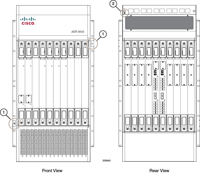
The chassis and its mounting brackets are equipped with ESD jacks (see the figure below). Use the jacks in conjunction with grounding wrist straps when handling the chassis and/or its components. The following figure shows the location of the jacks.
Before the you can use the ESD jacks on the ASR 5500 chassis and its mounting brackets, you must first connect the chassis to ground according to the instructions in the Chassis Installation chapter of this document.
Standards Compliance
FCC Warning
This device may not cause harmful interference.
This device must withstand any interference received, including interference that may cause undesired operation.
The system platform has been tested and found to comply with the limits for a Class A digital device pursuant to Part 15 of the FCC Rules and Regulations. These limits are designed to provide reasonable protection against harmful interference when this equipment is operated in a commercial environment. This equipment generates, uses, and can radiate radio-frequency energy and, if not installed and used in accordance with the instruction manual, may cause harmful interference to radio and television communications. Operation of this equipment in a residential area is likely to cause interference in which case the user will be required to correct the interference at his or her own expense.
Modifications to this product not authorized by Cisco could void the FCC approval and negate your authority to operate the product.
Shielded cables must be used with this unit to ensure compliance with the FCC Class A limits.