Contents
SSC Alarm Cabling
 Caution | The CO alarm interface of the SSC is suitable for connection to intra-building or unexposed wiring or cabling only. This interface MUST NOT be metallically connected to interfaces that connect to the outside plant (OSP) or its wiring. This interface is designed for use as an intra-building interface only (Type 2 or Type 4 ports as described in GR-1089-CORE, Issue 5) and requires isolation from the exposed OSP cabling. The addition of Primary Protectors is not sufficient protection in order to connect these interfaces metallically to OSP wiring. |
It includes the following sections:
- CO Alarm Interface
- Alarm Cutoff (ACO)
- Alarm Connector Pinout
- Electrical Characteristics
- CO Alarm Wiring Example
CO Alarm Interface
The Central Office (CO) Alarm interface on the SSC is a DB15 female connector that supports three low voltage, normally-closed/normally-open dry-contact relays. These Form C relays interface with an CO alarm monitor panel to trigger external audio and/or visual indicators.
Minor Alarm – This alarm is triggered when a high temperature is detected on a card, causing the fan tray to switch the fans to high speed.
- Major Alarm – This alarm is triggered when there is a:
Hardware failure that causes the card to be placed in an off-line state
PFU failure or removal from the chassis
Failure of one or more fans on any of the upper or lower fan tray units
Fan tray failure or any fan tray unit is removed from the chassis
Critical Alarm – This alarm is triggered when a degradation in service is detected. For example, if the system is supporting a large number of subscribers and DPCs are removed, the amount of available CPU and memory resources available for use are reduced.
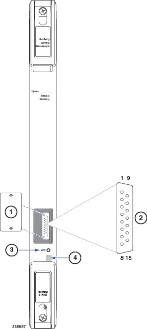
Alarm Connector Pinout
The CO alarm connector pinout is provided in the table below.
Use a Phillips #1 screwdriver to remove the two screws that secure the cover plate over the alarm connector.
| Pin | Alarm Level | Signal |
|---|---|---|
| 1 | Minor | Normally Open |
| 2 | Normally Closed | |
| 3 | — | Not connected |
| 4 | Major | Normally Open |
| 5 | Normally Closed | |
| 6 | — | Not connected |
| 7 | Critical | Normally Open |
| 8 | Normally Closed | |
| 9 | Minor | Minor, Common |
| 10 | — | Not connected |
| 11 | — | Not connected |
| 12 | Major | Major, Common |
| 13 | — | Not connected |
| 14 | — | Not connected |
| 15 | Critical | Critical, Common |
Electrical Characteristics
Each of the three dry-contact, Form C relay switches is rated to support a maximum switching current of 1A@30VDC.
Caution | Never connect a high voltage/high current device such as an audible alarm/siren or incandescent lamp directly to the EO alarm connector. |
CO Alarm Wiring Example
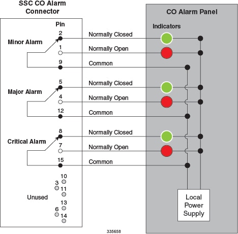
The figure below depicts how the three dry-contact (no voltage supplied) relay contacts can each control up to two alarming devices. In this example the SSC CO alarm interface is connected to a CO Alarm Panel, where green LEDs are wired to indicate normal operation, and red LEDs are wired to indicate alarm conditions.
With all relays de-energized, the green LEDs are illuminated. If an alarm relay is energized, its NO (normally open) contact closes; the green LED is extinguished and the red LED is illuminated.