Contents
- Technical Specifications
- Physical Dimensions
- Environmental Specifications
- Environmental Parameters
- Environmental Standards
- Chassis Air Flow
- Clearance
- Mounting Requirements
- Power Requirements
- Power Specifications
- Example Power Calculations
- DPC/UPDC Full Chassis
- DPC2/UDPC2 Full Chassis
- Central Office Alarm Interface
- Chassis Grounding
Technical Specifications
- Physical Dimensions
- Environmental Specifications
- Mounting Requirements
- Power Requirements
- Central Office Alarm Interface
- Chassis Grounding
Physical Dimensions
The ASR 5500 can be mounted in any standard (EIA-310-D, IEC 60297) 19-inch (482.6 mm) equipment cabinet or telecommunications rack. The table below lists the dimensions for the chassis and each component that can be placed within the chassis.
| Component | Notes | Height | Width | Depth | Weight |
|---|---|---|---|---|---|
| Chassis (empty) | 1 |
36.75 in. (93.3 cm) |
17.25 in. (43.8 cm) |
27.5 in. (69.8 cm) |
131 lbs (51.25 kg) |
| Chassis as shipped | 2 | 226 lbs (102.5 kg) | |||
| Chassis (maximum) | 3 | 36.75 in. (93.3 cm) | 17.25 in. (43.8 cm) | 32.0 in. (81.3 cm) | 450 lbs (204.1 kg) |
| Chassis (shipping) | 4, 5 | 50 in. (127 cm) | 24 in. (61 cm) | 32 in. (81.3 cm) | 265 bs (120.2 kg) |
| Fan Tray – Front | — | 1.625 in. (4.13 cm) | 16.37 in. (41.6 cm) | 5.625 in. (14.3 cm) | 5.5 lbs (2.5 kg) |
| Fan Tray – Rear | — | 2.125 in. (5.4 cm) | 16.87 in. (42.9 cm) | 18.5 in. (47 cm) | 24.5 lbs (11.1 kg) |
| Power Filter Unit | — | 3.5 in. (8.9 cm) | 8.5in. (21.6 cm) | 21.5 in. (54.6 cm) | 15 lbs (6.8 kg) |
| FSC | — | 19.75 in. (50.2 cm) | 1.75 in. (4.44cm) | 6.75in. (17.1 cm) | 6 lbs (2.7 kg) |
| SSC | — | 4.5 lbs (2 kg) | |||
| MIO or UMIO | 6 |
21.75 in. (55.24 cm) |
1.75 in. (4.44 cm) |
19.5 in. (49.5 cm) |
18 lbs (8.16 kg) |
| DPC or UDPC | — | 18.5 lbs (8.4 kg) | |||
| DPC2 or UDPC2 | — | 22.7 lbs (10.3 kg) | |||
| Baffle panel – front | — | 19.75 in. (50.2 cm) | 1.75 in. (4.44 cm) | 6.25 in. (7 cm) | 1 lb (0.45 kg) |
| Baffle panel – rear | — | 21.75in. (55.2 cm | 18.625 in. 47.3 cm) | 2.5 lbs (1.13 kg) |
-
No PFUs or fan trays.
-
Includes four Fan Tray Units and two PFUs.
-
Depth and weight with cable management tray installed and closed, and all card slots filled.
-
Includes shipping container, accessory box, and chassis with four Fan Tray Units and two PFUs
-
Width on the pallet forks.
-
Without cable management bracket.
Environmental Specifications
The ASR 5500 is designed for deployment in unattended sites equipped with redundant power systems, redundant data communications connections, environmental controls (air conditioning, fire suppression), security devices and controlled access.
Environmental Parameters
The table below lists the environmental parameters (operating and storage) for the ASR 5500 chassis.
| Parameter | Subparameter | Range |
|---|---|---|
| Temperature | Operating | 0 degrees C to +40 degrees C (32 degrees F to 104 degrees F) |
| Short Term 1 | -5 degrees C to +50 degrees C (23 degrees F to 122 degrees F) | |
| Storage | -40 degrees C to +70 degrees C (-40 degrees F to 158 degrees F) | |
| Humidity | Operating | 20 to 80 percent non-condensing |
| Storage | 10 to 95 percent non-condensing | |
| Altitude | Operating | 197 ft. (60m) below to 5,905 ft. (1,800m) above sea level, maximum 40 degrees C (104 degrees F) |
| 5,905 ft. (1,800m) to 13,123 ft. (4000m) above sea level, maximum 30 degrees C (86 degrees F) | ||
| Non-operating | 197 ft. (60m) below to 49,212 ft. (15,000m) above sea level | |
| Acoustic Noise | 23 degrees C (73.4 degrees F) | 81 dB (within GR-63 limits for unattended operation) |
| 27 degrees C (80.6 degrees F) | 81 dB (within GR-63 limits for unattended operation) | |
| Max. Fan Speed | 96 dB (as measured during GR-63 R4-97 testing) |
- Short-term refers to a period of not more than 96 consecutive hours and a total of not more than 15 days in 1 year. (This refers to a total of 360 hours in any given year, but no more than 15 occurrences during that 1-year period.)
Environmental Standards
The ASR 5500 has been successfully tested for compliance with the environmental standards listed in table below.
| Type | Standard |
|---|---|
| Acoustic Noise | Telcordia GR-63 Criterion [128] |
| Airborne Contaminants, Indoor Levels | Telcordia GR-63 Criterion [125] |
| Airborne Contaminants, Outdoor Levels | Telcordia GR-63 Criteria [126, 127] |
| Altitude | Telcordia GR-63 Criteria [74, 76] |
| Earthquake Zone 4 | Telcordia GR-63 Criteria [110-112, 114, 115, 117, 119] |
| Electromagnetic Compatibility and Electrical Safety | Telcordia Technologies GR-1089-CORE |
| Operational Thermal, Operating Conditions | Telcordia GR-63 Criteria [72, 73] |
| Operational Thermal, Short-term Conditions | Telcordia GR-63 Criteria [72, 73] |
| Storage Environments, and Transportation and Handling | Telcordia GR-63 Criteria [69-71, 107-109, 124] |
| Thermal Heat Dissipation | Telcordia GR-63 Criteria [77, 79] |
| Electromagnetic Compatibility and Electrical Safety | Telcordia Technologies GR-1089-CORE |
| Radiated Emissions (Electric Field) | FCC 47 CFR, PART 15, CLASS A |
| Electromagnetic Compatibility | ETSI EN 300 386 v1.4.1 |
| Environmental Conditions and Environmental Tests for Telecommunications Equipment | ESTI EN 300 019, ETSI EN 300 753 |
Chassis Air Flow
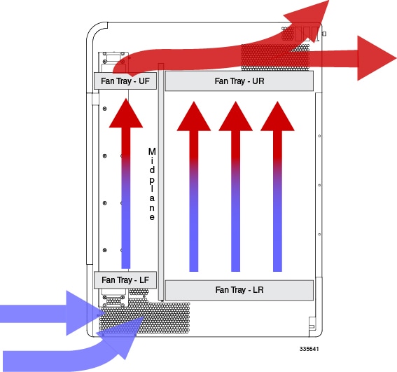
Air flow within the ASR 5500 complies with Telcordia recommendations to ensure vertical convection cooling of the system.
As shown in the figure below, the lower fan trays pull ambient air inward from the front and side intake vents located near the bottom of the chassis. The air absorbs heat from system components as it passes over them.
The upper fan trays pull heated air up through the chassis and exhaust it through the side and rear exhaust vents located near the top rear of the chassis.
 Caution | The environmental control system within the installation site must be able to maintain the ambient environment within the limits for operating temperature and humidity. |
Clearance
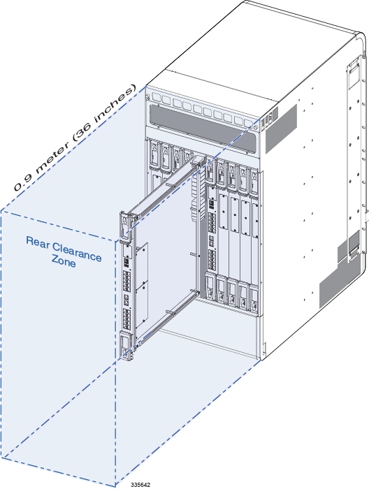
Ensure that the equipment rack or cabinet hardware does not hinder air flow at any of the intake or exhaust vents. Allow approximately 0.9 meter (36 inches) at the front and rear of the chassis for air flow and maintenance access.
Caution | The rear clearance is also necessary for removing and replacing the rear cards and fan trays (see the figure below). These units are very large and require additional clearance from cable management bars, PDUs, etc. |
Mounting Requirements
Each ASR 5500 chassis occupies 21 RU (rack units) within any standard (EIA-310-D, IEC 60297) 19-inch (482.6 mm) equipment rack or cabinet using the mounting brackets supplied with the chassis. Extension brackets (not supplied) may be used in conjunction with the chassis mounting brackets to install the chassis in a standard 23-inch (584.2 mm) cabinet or rack. The chassis mounting brackets may be repositioned to support flush and mid-mount installations.
The chassis footprint is approximately 19-inch (48.26 cm) wide by 26.75 in. (67.9 cm) long.
This footprint does not include the rear-mounted cable management tray.
Two ASR 5500 chassis fit in 42 RU (73.5 in.) of space within an equipment rack or cabinet.
Rack mounting requires the use of industry-standard equipment racks or cabinets with supplier-recommended fasteners. The rack should be rated to accommodate the weight of one or two chassis and any auxiliary equipment.
Power Requirements
Power Specifications
The table below lists the power requirements for individual components of the ASR 5500 chassis.
| Component | Parameter | Values | Notes |
|---|---|---|---|
| Chassis | Input voltage per feed circuit (nominal) | -48VDC | — |
| Input voltage per feed circuit (maximum) | -40VDC to -60VDC | — | |
| Power feed circuits per each PFU | 4 | 1 | |
| TUV rated peak current load per feed | 80 amps @ -40 VDC | 2 | |
| Maximum power load per chassis | 12,800 watts | 3 | |
| Cards | |||
| FSC | Maximum power | 150 watts | — |
| SSC | Maximum power | 10 watts | — |
| MIO or UMIO | Maximum power | 650 watts | — |
| DPC or UDPC | Maximum power | 630 watts | — |
| DPC2 or UDPC2 | Maximum power | 760 watts | — |
| Fan Tray Unit | |||
| Front | Maximum power | 60 watts each (2 per chassis | — |
| Rear | Maximum power | 940 watts each (2 per chassis) | — |
- A minimum of four -48VDC power feeds are required on PFU-A to provide non-redundant power to a chassis and all its cards. Four additional power feeds are required on PFU-B for power redundancy (4+4 = 8).
- Although the chassis may not draw 12.8 kW, a minimum of four 80-amp -48VDC feeds must be properly sized and wired to PFU-A to assure that all chassis slots are powered and available for future expansion. All power inputs on PFU-A must be connected to live power feeds to assure that all chassis card slots are energized.
- The type and number of cards installed in the ASR 5500 chassis determine the actual -48VDC power draw. See Example Power Calculations.
The power source must be a UL/CSA listed device with a regulated output no greater than -60VDC.
The DC power Battery Return (BR) or positive terminal, must be grounded at the source end (power feed or mains power end).
The DC power BR input terminal of the ASR 5500 is not connected to the equipment frame (chassis) and is configured as DC-I in compliance with GR-1089-CORE (sec.9.8.3).
Example Power Calculations
DPC/UPDC Full Chassis
This calculation assumes that a fully redundant ASR 5500 chassis will be equipped with DPC/UDPCs.
(8) DPC/UDPCs [8x630w] = 5040 watts
(2) MIO/UMIOs [2x650w] = 1300 watts
(4) FSCs [4x150w] = 600 watts
(2) SSCs [2x10w] = 20 watts
Fan Units [front and rear] = 2000 watts
Total = approximately 9 kW
DPC2/UDPC2 Full Chassis
This calculation assumes that a fully redundant ASR 5500 chassis will be equipped with DPC2/UDPC2s.
(8) DPC2/UDPC2s [8x760w] = 6080 watts
(2) MIO/UMIOs [2x650w] = 1300 watts
(4) FSCs [4x150w] = 600 watts
(2) SSCs [2x10w] = 20 watts
Fan Units [front and rear] = 2000 watts
Total = approximately 10 kW
Central Office Alarm Interface
The Central Office (CO) alarm interface on the SSC is a DB15 connector that supports three dry-contact (no voltage supplied) relay switches. Each of the Form C relays is rated to support a maximum switching current of 1A@30VDC.
Caution | The alarm relay contacts should never be connected to high current draw devices, such as sirens or flashing incandescent lamps. |
The three relays support both normally-open (NO) and normally-closed (NC) devices. For additional information, refer to the SSC Alarm Cabling chapter for details.