Software Configuration Guide (Version 1.1)
Bias-Free Language
The documentation set for this product strives to use bias-free language. For the purposes of this documentation set, bias-free is defined as language that does not imply discrimination based on age, disability, gender, racial identity, ethnic identity, sexual orientation, socioeconomic status, and intersectionality. Exceptions may be present in the documentation due to language that is hardcoded in the user interfaces of the product software, language used based on RFP documentation, or language that is used by a referenced third-party product. Learn more about how Cisco is using Inclusive Language.
- Updated:
- March 17, 2015
Chapter: Overview
Overview
The Cisco VG248 Analog Phone Gateway (VG248) enables you to integrate analog telephones, modems, and fax machines with the Cisco CallManager IP telephony system. You can also integrate legacy voice mail and PBX systems with Cisco CallManager using Simplified Message Desk Interface (SMDI).
The following topics provide an overview of the supported features and analog devices and describe the supported data and voice protocols:
•![]() Understanding How the VG248 Integrates with the Cisco IP Telephony Network
Understanding How the VG248 Integrates with the Cisco IP Telephony Network
•![]() Understanding How the VG248 Supports Telephony Features
Understanding How the VG248 Supports Telephony Features
For details on using SMDI to integrate your existing voice mail systems with Cisco CallManager see the Chapter 5, "Integrating Cisco CallManager with Voice Mail Systems Using SMDI."
Understanding How the VG248 Integrates with the Cisco IP Telephony Network
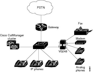
The Cisco VG248 is a high-density gateway for using analog phones, fax machines, modems, and speakerphones within the Cisco IP telephony network (see Figure 1-1). The Cisco VG248 offers 48 fully-featured analog phone lines to be used as extensions to the Cisco CallManager system in a compact 19-inch rack-mount chassis.
Figure 1-1 VG248 Integrated in the Cisco IP Telephony Network
Understanding How the VG248 Supports Telephony Features
Review the following sections to understand which telephony features are supported by the VG248 and to understand how they are implemented:
•![]() Understanding Voice-Mail Message Indicators
Understanding Voice-Mail Message Indicators
•![]() Understanding Call Control Modes
Understanding Call Control Modes
•![]() Understanding Caller ID Support
Understanding Caller ID Support
Supported Telephony Features
The VG248 supports the following features:
•![]() Call Transfer (supervised and blind)
Call Transfer (supervised and blind)
•![]() Conference
Conference
•![]() Call Waiting (with calling party ID display)
Call Waiting (with calling party ID display)
•![]() Hold (including switch between parties on hold)
Hold (including switch between parties on hold)
•![]() Call Forward All
Call Forward All
•![]() Send All Calls to Voice Mail
Send All Calls to Voice Mail
•![]() Pickup
Pickup
•![]() Call Voice Mail
Call Voice Mail
•![]() Speed Dial (maximum of 9 speed dials)
Speed Dial (maximum of 9 speed dials)
•![]() Last Number Redial
Last Number Redial
•![]() Caller ID
Caller ID
To understand how users access and use these features, see Table 1-1.
Understanding Voice-Mail Message Indicators
The VG248 can receive message-waiting indicator (MWI) information from Cisco CallManager and send it to analog phones. The VG248 sends MWI messages using any of the following methods:
•![]() Playing stutter dial tone when a user picks up the phone
Playing stutter dial tone when a user picks up the phone
•![]() Illuminating the MWI lamp on the phone
Illuminating the MWI lamp on the phone
•![]() Using caller ID mechanism to send information to the LCD screen on the phone
Using caller ID mechanism to send information to the LCD screen on the phone
You can enable or disable any of these options. See the "Choosing Message Waiting Indicator Type" section on page 3-11 for details.
Understanding Call Control Modes
The VG248 supports different call control modes, which indicate how users access and use the supported telephony features. You can choose the call control mode appropriate to the specific needs of your users and the abilities of your analog devices. The supported call control modes include:
To understand the differences among the three modes, keep in mind the following tips:
•![]() The three modes differ in how they support transfer and conference.
The three modes differ in how they support transfer and conference.
•![]() All modes support call waiting, and you can disable it on a per port basis using Cisco CallManager.
All modes support call waiting, and you can disable it on a per port basis using Cisco CallManager.
•![]() All modes support feature codes for speed dial, redial, call forward and pickup, and you can define or disable them on a per device basis.
All modes support feature codes for speed dial, redial, call forward and pickup, and you can define or disable them on a per device basis.
•![]() Users can access features using the hook flash, 0-9, *, or # buttons, depending on how you have configured the feature codes.
Users can access features using the hook flash, 0-9, *, or # buttons, depending on how you have configured the feature codes.
•![]() You cannot use a double flash hook.
You cannot use a double flash hook.
See the "Choosing the Call Control Mode" section on page 3-4 for details about setting the call control mode on the VG248.
Basic
This mode provides the most basic phone interface with no call transfer or conference features. Basic mode might work best for fax machines or modems. See Table 1-1 for details about how the telephony features are accessed in basic mode.
Standard
Standard is the default telephony mode, and it provides standard Bellcore features, such as used in North America.
Users use the flash button or hook flash to transfer, conference and hold calls, with the following requirements:
•![]() You cannot use a double hook flash to end a call.
You cannot use a double hook flash to end a call.
•![]() When putting calls on hold, the first call can be either incoming or outgoing.
When putting calls on hold, the first call can be either incoming or outgoing.
•![]() When transferring a call or establishing conferences, the second call must be outgoing.
When transferring a call or establishing conferences, the second call must be outgoing.
Users also use feature codes to activate other features in standard mode. See Table 1-1 for details about how the telephony features are accessed in standard mode.
Feature
For simple calls, the feature mode is indistinguishable from the standard mode. While on calls, users use the flash button or hook flash to get a second dial tone to dial a second party. However, users then must enter feature codes to transfer the call or establish a conference.
When using feature mode with two calls established, the hook flash cycles around four states:
1. ![]() First call connected
First call connected
2. ![]() Feature code tone
Feature code tone
3. ![]() Second call connected
Second call connected
4. ![]() Feature code tone
Feature code tone
These different states enable you to keep both calls active and switch between them. Thus, unlike Standard mode you can keep both calls active for as long as you want and freely switch between them.
To transfer or conference, you need to enter the relevant feature code at one of the feature tones (which are similar to dial tones except you can only enter feature codes rather than being able to dial a directory number).
See Table 1-1 for details about how the telephony features are accessed in feature mode
|
|
|
|
|||
|---|---|---|---|---|---|
|
|
|
|
|||
*1 |
*2 |
*1 |
*2 |
*1 |
*2 |
*3 |
*4 |
*3 |
*4 |
*3 |
*4 |
*5 |
*6 |
*5 |
*6 |
*5 |
*6 |
*7 |
*8 |
*7 |
*8 |
*7 |
*8 |
*9 |
*9 |
*9 |
|||
|
|
|
|
|||
*0 |
*0 |
*0 |
|||
|
|
|
|
|||
*# |
*# |
*# |
|||
|
|
|
|
|||
**0 |
**0 |
**0 |
|||
|
|
|
|
|||
**1 number |
**1 number |
**1 number |
|||
|
|
|
|
|||
**2 |
**2 |
**2 |
|||
|
|
|
|
|||
**3 |
**3 |
**3 |
|||
|
|
|
|
|||
Hook flash to answer and switch between calls. |
Hook flash to answer and switch between calls. |
Hook flash to answer and switch between calls. |
|||
|
|
|
||||
Call 1, hook flash, call 2, hang up. |
Call 1, hook flash, #2, call 2, hang up |
||||
|
|
|
||||
Call 1, hook flash, call 2, wait for call 2 to be answered, hang up |
Call 1, hook flash, call 2, wait for call 2 to be answered, hook flash, #2 |
||||
|
|
|
||||
Call 1, hook flash, call 2, hook flash |
Call 1, hook flash, call 2, hook flash, #3 |
||||
|
|
|||||
Call 1, hook flash, call 2, hook flash, #1 |
|||||
|
|
|||||
Call 1, hook flash, call 2; hook flash to toggle |
|||||
1 When forward all is activated, users hear a distinctive dial tone to indicate that all incoming calls are currently being forwarded to a different directory number. |
Understanding Caller ID Support
If you have activated caller ID on Cisco CallManager, the VG248 can collect that information and pass it on to analog phones. You can disable caller ID on a per port basis. This enables you to support caller ID on some analog phones and not on others (see the "Enabling Caller ID" section on page 3-11 for details).
The VG248 supports the following caller ID standards:
•![]() Bellcore GR-30-CORE—North America
Bellcore GR-30-CORE—North America
•![]() ETS 300 648 and ETS 300 659-1—Europe (excluding the United Kingdom)
ETS 300 648 and ETS 300 659-1—Europe (excluding the United Kingdom)
•![]() British Telecom SIN227 and SIN 242—United Kingdom
British Telecom SIN227 and SIN 242—United Kingdom
When a call arrives, the VG248 sends the following information:
•![]() Time and date information
Time and date information
•![]() Calling number up to 18 digits when available, otherwise the reason why number is unavailable
Calling number up to 18 digits when available, otherwise the reason why number is unavailable
•![]() Calling name up to 20 characters when available
Calling name up to 20 characters when available
Supported Analog Devices
The VG248 has a maximum ringer equivalency number (REN) load of three (3) analog devices per line (using a shared directory number), and only two of these devices can be off-hook at any one time.
You should use analog devices designed to work in the country in which you are using the VG248. For example, if you are using the VG248 in the United Kingdom, you should use analog devices designed for use in that country.
These sections provide an overview of the types of analog devices supported by the VG248:
•![]() Private Line Automatic Ringdown Phones
Private Line Automatic Ringdown Phones
Analog Phones
The VG248 supports analog phones and the standard telephony features available on them.
Speakerphones
The VG248 performs line echo cancellation, but it does not perform acoustic echo cancellation. Speakerphones with built-in echo cancellation such as the Polycom-brand phones should work fine. However the voice quality might be unsatisfactory when using a speakerphone that does not perform acoustic echo cancellation itself.
Private Line Automatic Ringdown Phones
A telephone configured as a Private Line Automatic Ringdown (PLAR) telephone dials a pre-configured number when it goes off-hook. You cannot use PLAR phones to dial any other numbers. Telephones in hotel lobbies and airports are often configured in this way.
Cisco CallManager release 3.0 and later can be configured to support the PLAR phone feature for an IP phone or for an analog telephone connected to the VG248.
Fax Machines
The VG248 supports fax machines in pass-through and Cisco fax relay modes. In fax pass-through mode, the gateways do not distinguish a fax call from a voice call. Cisco fax relay offers a more reliable way of transporting the fax data in order to increase the data rate. However, the terminating gateway must also support Cisco fax relay. If necessary, you can disable Cisco fax relay (see the "Disabling Cisco Fax Relay" section on page 3-3 for details).
Modems
The VG248 supports modems in pass-through mode.
Supported Protocols
The VG248 supports several industry-standard and Cisco networking protocols required for voice communication over an IP network. Additionally, the VG248 supports protocols required for remote network management.
These sections provide an overview of the protocols supported by the VG248:
Data and Voice Protocols
The VG248 supports the following data and voice communication protocols.
•![]() Internet Protocol (IP)—addresses and sends packets across the network.
Internet Protocol (IP)—addresses and sends packets across the network.
•![]() Internet Group Management Protocol (IGMP)—used to report multicast group memberships
Internet Group Management Protocol (IGMP)—used to report multicast group memberships
•![]() Trivial File Transfer Protocol (TFTP)—allows you to transfer files over the network.
Trivial File Transfer Protocol (TFTP)—allows you to transfer files over the network.
•![]() HyperText Transfer Protocol (HTTP)—defines how messages are formatted and transmitted, and what actions Web servers and browsers should take in response to various commands.
HyperText Transfer Protocol (HTTP)—defines how messages are formatted and transmitted, and what actions Web servers and browsers should take in response to various commands.
•![]() File Transfer Protocol (FTP)—allows you to transfer files over the network.
File Transfer Protocol (FTP)—allows you to transfer files over the network.
•![]() Dynamic Host Configuration Protocol (DHCP)—dynamically allocates and assigns an IP address to network devices.
Dynamic Host Configuration Protocol (DHCP)—dynamically allocates and assigns an IP address to network devices.
•![]() Real-Time Transport Protocol (RTP)—enables transporting of real-time data, such as interactive voice and video over data networks.
Real-Time Transport Protocol (RTP)—enables transporting of real-time data, such as interactive voice and video over data networks.
•![]() Skinny Client Control Protocol (SCCP)—enables communication between the VG248 and Cisco CallManager.
Skinny Client Control Protocol (SCCP)—enables communication between the VG248 and Cisco CallManager.
Network Management Protocols
The VG248 supports Simple Network Management Protocol (SNMP) and implements several industry-standard Management Information Bases (MIBs).
Understanding SNMP Support
The VG248 supports SNMP versions 1 and 2, enabling you to perform the following commands:
•![]() Get—Retrieve a specific node's value.
Get—Retrieve a specific node's value.
•![]() GetNext—Retrieve the first value present in the ordered tree whose node succeeds the one specified.
GetNext—Retrieve the first value present in the ordered tree whose node succeeds the one specified.
•![]() GetBulk—Retrieve bounded number of values whose nodes succeed, in the numerical ordering, the one specified. GetBulk is available only in SNMP v2.
GetBulk—Retrieve bounded number of values whose nodes succeed, in the numerical ordering, the one specified. GetBulk is available only in SNMP v2.
•![]() Set—Set a specific value.
Set—Set a specific value.
Understanding Trap Support
The VG248 generates the following general traps, as defined in RFC 1157:
•![]() Cold start—when the VG248 starts up and obtains an IP address
Cold start—when the VG248 starts up and obtains an IP address
•![]() Warm start—when the VG248 changes IP addresses
Warm start—when the VG248 changes IP addresses
•![]() Authentication failure—when an invalid community string is used
Authentication failure—when an invalid community string is used
You must have set at least one network management station in order for the VG248 to generate traps. See the "Configuring Trap Settings" section for details.
Understanding Supported MIBs
The VG248 supports the following MIBs.
RFC 1213
RFC 1213 is the basic MIB 2 specification which indicates the state of embedded interfaces and statistics for network protocols.
The VG248 supports RFC 1213 with the following caveats:
•![]() ifAdminStatus for the Ethernet interface cannot be written, and it is fixed at "up".
ifAdminStatus for the Ethernet interface cannot be written, and it is fixed at "up".
•![]() ifSpecificfor all interfaces returns as "0, 0".
ifSpecificfor all interfaces returns as "0, 0".
•![]() atTable cannot be written.
atTable cannot be written.
•![]() No "ip***" values can be written.
No "ip***" values can be written.
•![]() You cannot write to "tcpConnState" for an active TCP connection.
You cannot write to "tcpConnState" for an active TCP connection.
•![]() The VG248 does not implement the External Gateway Protocol (EGP).
The VG248 does not implement the External Gateway Protocol (EGP).
Interface MIB
This MIB is defined in RFC 1573 and extends the range of information available about a device's interfaces from that provided by the ifTable in RFC 1213. The VG248 implements this MIB for its Ethernet interface and the 48 FXS interfaces. However, the octet or packet count values are not available for the FXS interfaces because they are not applicable to these interface types.
RMON
The VG248 implements the Ethernet Statistics group in Remote Monitoring (RMON), with the exception of "EtherStatsStatus." This is fixed at "valid" and cannot be written.
Cisco CDP MIB
Cisco Discovery Protocol (CDP) is a method that Cisco devices use to advertise their presence and to discover information about other nearby devices. The VG248 supports CDP and implements this MIB. You can enable or disable CDP on the VG248. See the "Enabling CDP" section for details.
Cisco Process MIB
This MIB describes the processes currently running on the device. However, because the VG248 runs threads, rather than processes, the MIB is implemented with the following caveats:
•![]() The amount of memory allocated is not recorded on a per-thread basis. Therefore, cpmProcExtMemAllocated and cpmProcExtMemFreed are returned as 0.
The amount of memory allocated is not recorded on a per-thread basis. Therefore, cpmProcExtMemAllocated and cpmProcExtMemFreed are returned as 0.
•![]() All threads run at the same priority. Therefore, every process cpmProcExtPriority are returned as "normal."
All threads run at the same priority. Therefore, every process cpmProcExtPriority are returned as "normal."
•![]() It is not possible to change a process's priority, so attempts to write "cpmProcExtPriority" are unsuccessful.
It is not possible to change a process's priority, so attempts to write "cpmProcExtPriority" are unsuccessful.
Cisco Memory Pool MIB
This MIB allows detailed information to be retrieved for all memory pools present within a Cisco device. The VG248 implements this MIB, but because all dynamic memory management uses a single heap, the resulting table has one row, which is returned as "Processor".
Cisco EnvMon MIB
"EnvMon" refers to the on-board environmental monitor on the VG248 that monitors the internal voltage, power supply, temperature, and fan settings.
The VG248 routinely measures these values recording the information in the rows within the different tables:
•![]() ciscoEnvMonVoltageStatusTable—records voltage and power supply readings
ciscoEnvMonVoltageStatusTable—records voltage and power supply readings
•![]() ciscoEnvMonFanStatusTable—records fan status readings
ciscoEnvMonFanStatusTable—records fan status readings
•![]() ciscoEnvMonTemperatureStatusTable—records temperature settings
ciscoEnvMonTemperatureStatusTable—records temperature settings
You can use this MIB to access these recorded values. Also, if the VG248 detects readings beyond the acceptable limits, the device generates warning messages. See the "Troubleshooting Hardware Errors" section for details.
Cisco Voice Interface MIB
This Cisco proprietary MIB (CISCO-VOICE-IF-MIB.my) allows access to voice interface parameters such as gain values and echo cancellation status. The VG248 implementation of this MIB provides read access only. You can configure the gain values using the VG248 interface (see the "Setting the Output Gain" section on page 3-13 and the "Setting the Input Gain" section on page 3-14 for details).
Cisco Analog Voice Interface MIB
This Cisco proprietary MIB (CISCO-VOICE-ANALOG-IF-MIB.my) allows access to interface parameters related to the analog ports. These parameters include hardware issues such as electrical impedance value and ring frequency and user factors such as whether an attached handset is currently on- or off-hook. The electrical impedance value and ring frequency is determined by the country code you set in the VG248 (see "Identifying the Country Code for VG248" section on page 3-6 for details). You can modify the hook-flash timer using the VG248 interface (see "Changing the Hook Flash Timer for Analog Phones" section on page 3-7).
 Feedback