Software Configuration Guide (Version 1.1)
Bias-Free Language
The documentation set for this product strives to use bias-free language. For the purposes of this documentation set, bias-free is defined as language that does not imply discrimination based on age, disability, gender, racial identity, ethnic identity, sexual orientation, socioeconomic status, and intersectionality. Exceptions may be present in the documentation due to language that is hardcoded in the user interfaces of the product software, language used based on RFP documentation, or language that is used by a referenced third-party product. Learn more about how Cisco is using Inclusive Language.
- Updated:
- February 15, 2008
Chapter: Integrating Cisco CallManager with Voice Mail Systems Using SMDI
- Overview
- Choosing a Configuration Option
- Connecting the SMDI Links to the VG248
- Configuring VG248 SMDI Ports in CiscoCallManager
- Configuring SMDI Settings on the VG248
- Identifying the Pilot Directory Number
- Assigning Number of SMDI Ports
- Identifying the First Voice Mail Port Number
- Setting SMDI Number Length
- Allowing SMDI Number to be Truncated
- Setting the SMDI Number Format
- Assigning the Message Desk Number
- Forwarding MWIs to CiscoCallManager
- Forwarding MWIs to Async 2
- Forwarding INV Responses to Async 1
- Identifying the Directory Number for Setting MWI on CiscoCallManager
- Identifying the Directory Number for Clearing MWI on CiscoCallManager
- Entering a Keep Alive Number
- Configuring Disconnect Notification
- Verifying and Troubleshooting the SMDI Connection
Integrating Cisco CallManager with Voice Mail Systems Using SMDI
Simplified Message Desk Interface (SMDI) defines how phone systems provide voice mail systems with the information needed to intelligently process incoming calls. It is an industry-standard signaling protocol that supplies calling and called party identification and sets and clears Message Waiting Indicators (MWIs) through an RS-232 serial connection.
Using SMDI and the VG248, you can integrate your existing voice mail systems (such as Lyrix, Octel 200, Octel 250, Octel 300 and Octel 350) and legacy PBX systems with Cisco CallManager.
These sections provide details about designing, installing, configuring, and verifying this integration:
Overview
The VG248 generates call information in an SMDI format for all calls coming into any of the SMDI-enabled ports. The VG248 can also send and receive SMDI messages to and from other SMDI devices, such as other VG248 devices, a legacy PBX, or the legacy voice mail system.
The VG248 provides advantages to other methods used for integrating Cisco CallManager with SMDI-based voice mail systems, including:
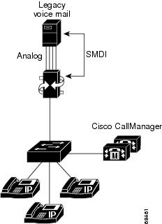
- Reliability for SMDI links using Cisco CallManager failover (see Figure 5-1).
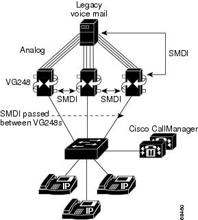
- Scalability by linking VG248 devices (see Figure 5-2).
- Multiple SMDI-based voice mail systems can be used on a single cluster, by using one VG248 per voice mail system (see Figure 5-2).
- A single voice mail system to be used by multiple clusters, by using one VG248 per cluster (see Figure 5-3).
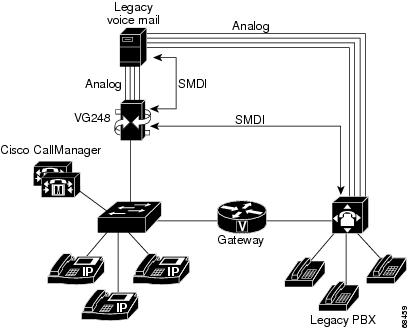
- A single voice mail system to be shared between Cisco CallManager and a legacy PBX (see Figure 5-4).
When the messages button is pressed on the IP Phone or the voicemail pilot is called; the CallManager routes the call to an available VG248 port in the same manner it would an IP Phone. The VG248 rings the port and waits for the voicemail system to answer the call. When the call is answered by the voicemail system, the VG248 sends the appropriate SMDI messages to the voicemail system through a sync port 1. If a message is left and a MWI needs to be updated, the VG248 contacts the CallManager using a virtual IP Phone, referred to as port 0 in the CallManager GUI, to send either a MWI on or MWI off to the appropriate IP Phone.
Table 5-1 provides an overview of the tasks required to implement this integration.
|
|
|
|
|---|---|---|
Choose one of the following methods:
|
||
Use Async 1 to connect to the voice mail system (any configuration) or SMDI source (chained or multiplexing configuration). Use Async 2 to connect VG248 devices together and to a legacy PBX system. |
||
You should verify that the voice mail service parameters are properly configured to support the SMDI-based voice mail system. |
See the “Configuring Voice Mail Parameters in Cisco CallManager” section. |
|
You must add a special port to Cisco CallManager that is used to set and clear MWI commands. |
||
You must add and configure the VG248 ports used for voice mail to the Cisco CallManager database. |
See the “Adding and Configuring Voice Mail Ports in Cisco CallManager” section. |
|
You should update the voice mail settings for the end-user phones that are using the SMDI-based voice mail system. |
||
You must configure the local SMDI settings on the VG248. Some of these SMDI settings must match settings on the voice mail system or Cisco CallManager. |
||
You can check the status of the SMDI connections to help resolve any problems. |
See the “Verifying and Troubleshooting the SMDI Connection” section. |
Choosing a Configuration Option
You can use the VG248 to integrate SMDI-based voice mail systems with Cisco CallManager in different configurations depending on your needs:
- Basic—if you need 48 or fewer voice mail ports and do not need to integrate with multiple Cisco CallManager clusters or a legacy PBX system.
- Chained—if you need more than 48 voice mail ports; can be used with the multiplexing configuration.
- Multiplexing—if you need to integrate with multiple Cisco CallManager clusters or with a legacy PBX system.
These sections provide additional information about these methods:
Basic Configuration
In the basic configuration (see Figure 5-1), you can use a single VG248 device to connect up to 48 voice channels to a voice mail system. This configuration enables you to use your existing voice mail system and integrate it with Cisco CallManager using SMDI.
When using the VG248 in this configuration, you have a more flexible failover system than when using a single Cisco CallManager server for SMDI integration. When connecting SMDI directly to Cisco CallManager, if that Cisco CallManager system fails, the SMDI link goes down. The link cannot automatically be switched or transferred to another Cisco CallManager system. However, if you are using the VG248 and the primary Cisco CallManager system fails, the VG248 automatically switches to its backup Cisco CallManager system, and the SMDI link remains.
When configuring the VG248 using the basic configuration, refer to these tips. Note, however, that this is not a complete list of the items you must configure; these are tips specific to the basic configuration. Refer to the “Configuring SMDI Settings on the VG248” section for a description of all SMDI configuration tasks.
- The VG248 should be set to forward MWI commands to Cisco CallManager. See the “Forwarding MWIs to Cisco CallManager” section for details.
- If the VG248 is set to forward MWI commands to Cisco CallManager, you must set the MWI directory numbers in Cisco CallManager. See the “Identifying the Directory Number for Setting MWI on Cisco CallManager” section and “Identifying the Directory Number for Clearing MWI on Cisco CallManager” section.
Figure 5-1 Basic Configuration of VG248 SMDI Integration
Chained Configuration
Each VG248 system enables you to use up to 48 ports for voice mail access. If you need more than 48 ports, you can use the chained configuration. The chained configuration (see Figure 5-2) enables you to connect multiple VG248 devices together, expanding the number of voice ports available for your voice mail integration.The SMDI information is shared and passed between the VG248 devices via the Async ports.
When using multiple VG248 systems, refer to these tips. Note, however, that this is not a complete list of the items you must configure; these are tips specific to the chained configuration. Refer to the “Configuring SMDI Settings on the VG248” section for a description of all SMDI configuration tasks.
- All VG248 systems connected together must be connected to a single voice mail system.
- Verify that you identify the first voice mail port correctly on each VG248 device. See the “Identifying the First Voice Mail Port Number” section for details.
- The first VG248 per CallManager cluster should be set to forward MWI commands to Cisco CallManager. See the “Forwarding MWIs to Cisco CallManager” section for details.
- You do not need to set the VG248 systems to forward MWI commands along the Async 2 connection unless a second cluster or a legacy voice mail system is attached to the end of the SMDI chain. For example, if you are using the chained configuration in conjunction with the multiplexing configuration. See the “Forwarding MWIs to Async 2” section.
- If a VG248 device is configured to forward MWI commands to Cisco CallManager, you must identify the MWI directory numbers used in Cisco CallManager. See the “Identifying the Directory Number for Setting MWI on Cisco CallManager” section and “Identifying the Directory Number for Clearing MWI on Cisco CallManager” section.
- All VG248 systems connected together should use the same “Message Desk Number” value. See the “Assigning the Message Desk Number” section for details.
Figure 5-2 Chained Configuration of VG248 SMDI Integration
Multiplexing Configuration
This method enables you to share a single voice mail system with multiple Cisco CallManager systems or another PBX system. Using the multiplexing configuration, you can integrate SMDI with multiple PBX systems, including:
- Multiple Cisco CallManager clusters (see Figure 5-3)
- Legacy PBX system and Cisco CallManager (see Figure 5-4)
When integrating SMDI links from more than one PBX system, refer to these tips. Note, however, that this is not a complete list of the items you must configure; these are tips specific to the multiplexing configuration. Refer to the “Configuring SMDI Settings on the VG248” section for a description of all SMDI configuration tasks.
- If connecting to a legacy PBX, all VG248 devices should be set to forward MWIs to Async 2. See the “Forwarding MWIs to Async 2” section.
- At least one VG248 per cluster should be set to forward MWI commands to Cisco CallManager. See the “Forwarding MWIs to Cisco CallManager” section.
- If you are not using a legacy PBX, set the VG248 systems to forward MWI commands along the Async 2 connection. You do not need to set this on the VG248 system furthest away on the SMDI chain from the voice mail system. That VG248 device should be configured to forward MWI commands to Cisco CallManager. See the “Forwarding MWIs to Async 2” section.
- If the VG248 is set to forward MWI commands to Cisco CallManager, you must set the MWI directory numbers in Cisco CallManager. See the “Identifying the Directory Number for Setting MWI on Cisco CallManager” section and “Identifying the Directory Number for Clearing MWI on Cisco CallManager” section.
Figure 5-3 Multiplexing Configuration of VG248 Integration with Multiple Cisco CallManager Clusters
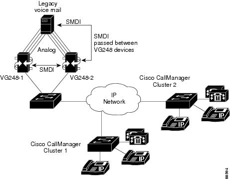
Figure 5-4 Multiplexing Configuration of VG248 Integration with Cisco CallManager and Legacy PBX
Connecting the SMDI Links to the VG248
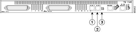
SMDI is an RS-232-based serial protocol, and the VG248 has two serial ports for supporting SMDI connections, the Async 1 and Async 2 ports (see Figure 5-5).
Figure 5-5 VG248 SMDI Connections
|
|
|
|
|
|
|
|
Both serial ports operate at a fixed rate and format of 9600 baud, no parity, 8 data bits, one stop bit, and no flow control. Use a standard RJ-45-to-RJ-45 rollover serial cable (up to 50 feet in length) and an RJ-45-to-DB-9 adapter to connect the VG248 to other SMDI devices using these ports:
- Async 1—the primary serial port used for connecting to the voice mail system (any configuration) or SMDI source (chained or multiplexing configuration). If you are using a single VG248 device, connect the voice mail system’s SMDI port to the Async 1 port on the VG248. With multiple VG248 devices, use the Async 1 port to connect to the previous VG248 device’s Async 2 port.
- Async 2—used for connecting multiple VG248 devices together. If there are multiple VG248 devices in use, connect the Async 2 port of the first VG248 device (which is connected directly to the voice mail system via the Async 1 port) to the next VG248 device’s Async 1 port. Continue to connect all the VG248 devices in the chain similarly. If you are connecting a legacy PBX system to the SMDI chain, connect the Async 2 port of the last chained VG248 device to the SMDI port of the legacy PBX.
Configuring VG248 SMDI Ports in Cisco CallManager
When using the VG248 to integrate SMDI-based voice mail systems with Cisco CallManager, you must make changes to Cisco CallManager to support the VG248 and the end-user phones that will use this voice mail system.
These sections provide details about the necessary changes:
- Configuring Voice Mail Parameters in Cisco CallManager
- Adding the MWI Port to Cisco CallManager
- Adding and Configuring Voice Mail Ports in Cisco CallManager
- Configuring End-User Phones
Configuring Voice Mail Parameters in Cisco CallManager
You need to update some of the Cisco CallManager service parameters to support the SMDI-based voice mail system and the VG248.
Step 1![]() From Cisco CallManager, choose Service > Service Parameters.
From Cisco CallManager, choose Service > Service Parameters.
Step 2![]() From the Server drop-down list box, choose a server.
From the Server drop-down list box, choose a server.
Step 3![]() From the Services list, choose Cisco CallManager.
From the Services list, choose Cisco CallManager.
Step 4![]() Enter the settings described in Table 5-2 .
Enter the settings described in Table 5-2 .
|
|
|
|---|---|
Enter the number users use to access their voice mail messages. This number should correspond to the directory number of the first voice mail port (see the “Adding and Configuring Voice Mail Ports in Cisco CallManager” section) and the pilot directory number entered on the VG248 (see the “Identifying the Pilot Directory Number” section). If you are connecting multiple VG248 systems to more than one voice mail system, you have multiple hunt groups. These hunt groups require different voice mail access numbers. For efficiency, enter the directory number of the largest hunt group as the VoiceMail parameter and ensure that the AdvancedCallForwardHopFlag is set to true. Note The directory number entered in the VoiceMail parameter should not correspond to the directory numbers assigned to any of the ports attached to a VG248 device. |
|
Set this value to be at least as high as the total number of SMDI ports in use across all VG248 devices. |
|
Set this flag to True, if you want Cisco CallManager to use translation patterns to convert voice message box numbers into directory numbers when your voice mail system issues a command to set a message waiting indicator. |
Adding the MWI Port to Cisco CallManager
When using SMDI, the VG248 requires an extra port registered with Cisco CallManager. The VG248 uses this port when setting or clearing MWIs on phones. On the VG248, this port is defined as port 00 and referred to as the “Device level CallManager connection” on the port status screen (see “Verifying Port Status and Displaying Port Statistics” section for details).
To add the MWI port to Cisco CallManager, follow these steps.
Step 1![]() From Cisco CallManager, choose Devices > Add a New Device.
From Cisco CallManager, choose Devices > Add a New Device.
Step 2![]() Choose Cisco VGC Phone from the Phone type menu.
Choose Cisco VGC Phone from the Phone type menu.
Step 4![]() Enter a Description for this port in the Description field such as voice mail system port x, where voice mail system is the name of your voice mail system and x is the port number on the VG248. For example, Generic Voice Mail port 1.
Enter a Description for this port in the Description field such as voice mail system port x, where voice mail system is the name of your voice mail system and x is the port number on the VG248. For example, Generic Voice Mail port 1.

Note![]() This description is particularly useful if you are using the VG248 for analog and SMDI ports. Cisco CallManager does not distinguish between these two types of VGC phone types, and this description can help you quickly see which ports are used for analog devices and which are used for SMDI voice mail
This description is particularly useful if you are using the VG248 for analog and SMDI ports. Cisco CallManager does not distinguish between these two types of VGC phone types, and this description can help you quickly see which ports are used for analog devices and which are used for SMDI voice mail
Step 5![]() Enter the MAC address in the MAC Address field.
Enter the MAC address in the MAC Address field.
Each port must have a unique MAC address. Use this formula to calculate the MAC address for each port.
- The first two digits of the MAC address are dropped.
- The number is shifted two places to the left.
- 00 is added to the right.
For example, if the MAC address on the VG248 is 000039A44218, the MAC address registered for this port in Cisco CallManager is 0039A4421800.
Step 6![]() Select a Calling Search space that enables this MWI port to access all phones on which it might need to set or clear MWI commands.
Select a Calling Search space that enables this MWI port to access all phones on which it might need to set or clear MWI commands.
Adding and Configuring Voice Mail Ports in Cisco CallManager
Using Cisco CallManager, you must add and configure each of the ports on the VG248 that are SMDI-enabled. To Cisco CallManager, each port is recognized and managed as a phone with the VGC phone type. So, if you have 10 ports on the VG248 that are SMDI-enabled, you need to add these 10 VGC phones (or ports) to Cisco CallManager.
Note![]() If you plan to use the remaining 38 ports on the VG248 for analog devices, refer to the “Configuring the VG248 Analog Ports” section for instructions.
If you plan to use the remaining 38 ports on the VG248 for analog devices, refer to the “Configuring the VG248 Analog Ports” section for instructions.
Cisco CallManager enables you to automatically register the ports from the VG248 or manually add them to the Cisco CallManager database. However, auto-registration works best for analog devices (see the“Adding the VG248 to Cisco CallManager” section) rather than for the SMDI ports because of the additional configuration changes required for voice mail.
To add and configure a VG248 voice mail port to Cisco CallManager, follow these steps.
Step 1![]() From Cisco CallManager, choose Devices > Add a New Device.
From Cisco CallManager, choose Devices > Add a New Device.
Step 2![]() Choose Cisco VGC Phone from the Phone type menu.
Choose Cisco VGC Phone from the Phone type menu.
Step 4![]() Enter a Description for this port in the Description field such as voice mail system port x, where voice mail system is the name of your voice mail system and x is the port number on the VG248. For example, Generic Voice Mail port 1.
Enter a Description for this port in the Description field such as voice mail system port x, where voice mail system is the name of your voice mail system and x is the port number on the VG248. For example, Generic Voice Mail port 1.
Note![]() This description is particularly useful if you are using the VG248 for analog and SMDI ports. Cisco CallManager does not distinguish between these two types of VGC phone types, and this description can help you quickly see which ports are used for analog devices and which are used for SMDI voice mail
This description is particularly useful if you are using the VG248 for analog and SMDI ports. Cisco CallManager does not distinguish between these two types of VGC phone types, and this description can help you quickly see which ports are used for analog devices and which are used for SMDI voice mail
Step 5![]() Enter the MAC address in the MAC address field.
Enter the MAC address in the MAC address field.
Each port must have a unique MAC address. Use this formula to calculate the MAC address for each port.
- The first two digits of the MAC address are dropped.
- The number is shifted two places to the left.
- The two-digit port number is added to the right.
For example, if the MAC address on the VG248 is 000039A44218, the MAC address registered for port 12 in Cisco CallManager is 0039A4421812
Step 6![]() In the Directory Numbers list, click an unassigned line.
In the Directory Numbers list, click an unassigned line.
Step 7![]() Enter the settings described in Table 5-3
Enter the settings described in Table 5-3
|
|
|
|---|---|
Enter the directory number for this voice mail port. The first port must be assigned the directory number identified as the pilot directory number on the VG248 (see the “Identifying the First Voice Mail Port Number” section) and defined as the VoiceMail number in Service > Service Parameters in Cisco CallManager. For ease of managing these ports, assign consecutive directory numbers to the remaining voice mail ports. |
|
Set this to Off to disable it on each of the voice mail ports. |
|
Enter the directory number for the next VG248 voice mail port on the SMDI chain. For example, if the directory number for this port is 75001, enter 75002 to forward to the next available port. |
|
Enter the directory number for the next VG248 voice mail port on the SMDI chain. For example, if the directory number for this port is 75001, enter 75002 to forward to the next available port. |
Step 1![]() On the VG248, choose Configure > SMDI > Number of SMDI port s to set the number ports used for SMDI.
On the VG248, choose Configure > SMDI > Number of SMDI port s to set the number ports used for SMDI.
See the “Assigning Number of SMDI Ports” section for details.
Step 2![]() Choose Configure > Telephony > Port specific parameters. Ensure that ports from1 to the value set in Number of SMDI ports are enabled.
Choose Configure > Telephony > Port specific parameters. Ensure that ports from1 to the value set in Number of SMDI ports are enabled.
See the “Enabling a Specific Port” section for details.
Step 3![]() Choose Display > Port Status to verify that these voice mail ports are up-and-running.
Choose Display > Port Status to verify that these voice mail ports are up-and-running.
See the “Verifying Port Status and Displaying Port Statistics” section for details.
Configuring End-User Phones
You need to modify some settings on the end-user phones in Cisco CallManager to enable them to access the SMDI-based voice mail system.
You should modify these settings on any Cisco IP Phones and on any analog phones connected to the VG248 that require access to this voice mail system.
The following steps require that these phones have already been added to the Cisco CallManager database. If you need assistance adding an analog phone or a Cisco IP Phone, see the “Configuring the VG248 Analog Ports” section and the online help and documentation included with Cisco CallManager.
Step 1![]() From Cisco CallManager, choose Device > Phone.
From Cisco CallManager, choose Device > Phone.
Step 2![]() Enter search criteria to locate a specific phone.
Enter search criteria to locate a specific phone.
Step 3![]() Click the name of the phone to update.
Click the name of the phone to update.
Step 4![]() From the Directory Numbers list, click the line that you want to update.
From the Directory Numbers list, click the line that you want to update.
Step 5![]() Update the settings described in Table 5-4 .
Update the settings described in Table 5-4 .
|
|
|
|---|---|
Enter the voice mailbox that you want to associate with this line. When a call is forwarded to voice mail, Cisco CallManager sends the number that you enter here to your voice-mail application. The voice-mail system then leaves voice-mail messages in the configured mailbox. |
|
Enter the directory number for the first VG248 voice mail port. This forwards the call to voice mail. This number should match the number entered for the Voicemail parameter in Cisco CallManager (see Table 5-2 ). |
|
Enter the directory number for the first VG248 voice mail port. This forwards the call to voice mail. This number should match the number entered for the Voicemail parameter in Cisco CallManager (see Table 5-2 ). |
Configuring SMDI Settings on the VG248
To properly prepare the VG248 to support SMDI, you must modify some local configuration settings. Some of these SMDI settings must match settings on the voice mail system or Cisco CallManager. Therefore, you must be familiar with the configuration settings on those systems as well.
These sections provide details about the required configuration options:
- Identifying the Pilot Directory Number
- Assigning Number of SMDI Ports
- Identifying the First Voice Mail Port Number
- Setting SMDI Number Length
- Allowing SMDI Number to be Truncated
- Setting the SMDI Number Format
- Assigning the Message Desk Number
- Forwarding MWIs to Cisco CallManager
- Forwarding MWIs to Async 2
- Forwarding INV Responses to Async 1
- Identifying the Directory Number for Setting MWI on Cisco CallManager
- Identifying the Directory Number for Clearing MWI on Cisco CallManager
- Entering a Keep Alive Number
- Configuring Disconnect Notification
Identifying the Pilot Directory Number
The pilot directory number corresponds to the number users dial on their phones to access voice mail. The pilot directory number configured on the VG248 must match the VoiceMail service parameter configured in Cisco CallManager, which is available by choosing Service > Service Parameters in Cisco CallManager. This enables the VG248 to distinguish between calls made to retrieve a user’s voice mail from calls made to leave a voice mail for another user.
Step 1![]() From the main menu, choose Configure.
From the main menu, choose Configure.
Step 3![]() Choose Pilot directory number.
Choose Pilot directory number.
Step 4![]() Enter the number, which corresponds to the VoiceMail in Cisco CallManager.
Enter the number, which corresponds to the VoiceMail in Cisco CallManager.
Assigning Number of SMDI Ports
By default, none of the ports on the VG248 are configured to send SMDI information about calls made to those ports. To enable SMDI, you must assign the number of SMDI ports a value from 1 to 48. Using fewer than 48 ports for SMDI means that the remaining ports can be used for connecting analog phones, modems, or fax machines.
If you use fewer than 48 ports for SMDI, you must ensure that the SMDI ports are consecutive ports beginning with port 1. For example, if this value is set to “10”, VG248 ports 1 through 10 should be connected to the voice mail system and ports 11 to 48 are available for analog devices.
Step 1![]() From the main menu, choose Configure.
From the main menu, choose Configure.
Step 3![]() Choose Number of SMDI ports.
Choose Number of SMDI ports.
Step 4![]() Enter the number of SMDI ports.
Enter the number of SMDI ports.
Identifying the First Voice Mail Port Number
With a single VG248 connected to a voice mail system (such as in the basic configuration), port 1 on the VG248 should be connected to port 1 of the voice mail system, and similarly for the other VG248 ports.
However, with multiple VG248 devices connected to a single voice mail system (such as in the chained configuration) this simple mapping is possible only on the first VG248. On the other VG248 devices, port 1 must connect to higher voice mail port numbers.
Using this setting, you can identify the first port used on the voice mail system. This value should correspond to the port number on the voice mail system to which port 1 is connected. In all cases, connections from a single VG248 must use consecutive, successive ports of the voice mail system.
For example, if two VG248 devices are connected to a 96 port voice mail system, one VG248 connects to ports 1-48, and the other connects to ports 49-96. On the first VG248 device, set the First voice mail port number to 1 (the default value) and set the value to 49 on the second VG248.
As another example, if 80 voice mail ports were in use and two VG248 devices were each providing 40 ports, the Number of SMDI ports on each VG248 would be set to 40, and the First voice port number would be set to 1 on the first VG248 and 41 on the second VG248.
Step 1![]() From the main menu, choose Configure.
From the main menu, choose Configure.
Step 3![]() Choose First voice mail port number.
Choose First voice mail port number.
Step 4![]() Enter the voice mail pot index which corresponds to port 1 of the VG248.
Enter the voice mail pot index which corresponds to port 1 of the VG248.
Setting SMDI Number Length
Traditional SMDI includes caller and called party information as 7-digit numbers. If the number is shorter than 7 digits, extra digits (typically zeros) are added to the left. For example, the extension number “12345” becomes “0012345” when sent via SMDI. However, because 7 digits are not enough for external caller ID, an extended SMDI format is available that uses 10-digit numbers.
Most voice mail systems are flexible, supporting either SMDI format. However, some older systems insist on receiving exactly seven digits. Check the voice mail system’s documentation to determine which setting is most appropriate.
You can set the VG248 to output using either 7- or 10-digit numbers. It should match the value required by your voice mail system. You can also set the number length to <unpadded>, which indicates that the voice mail box numbers are always passed unmodified between Cisco CallManager and the analog voice mail system.
Step 1![]() From the main menu, choose Configure.
From the main menu, choose Configure.
Step 3![]() Choose SMDI number length.
Choose SMDI number length.
Step 4![]() Choose one of the following:
Choose one of the following:
Allowing SMDI Number to be Truncated
If SMDI extension numbers are longer than the traditional 7 or 10 digits, the VG248 can either pass on the entire number or truncate the extension number to the length you defined in the SMDI number length. If you have set the SMDI number length to unpadded, this setting has no effect.
Most voice mail systems can accept longer numbers, but some systems insist on exactly 7 or 10 digits. Check which format your system supports before selecting this option. If the SMDI number length is set to <unpadded>, this setting has no effect.
Step 1![]() From the main menu, choose Configure.
From the main menu, choose Configure.
Step 3![]() Choose Truncate SMDI number if too long.
Choose Truncate SMDI number if too long.
Step 4![]() Choose one of the following:
Choose one of the following:
Setting the SMDI Number Format
When the SMDI number length is configured to 7 or 10 digits, the VG248 adds digits to any SMDI extension numbers that are shorter. Normally, it does so by adding zeroes to the left of the number, so that, for example, “1234” becomes “0001234” in the 7 digit case.
However, the SMDI number format allows other digits to be used. For example, with a SMDI number format of 1234567, the extension number 8989 would become 1238989. Zeroes are used for any additional required digits. So, if SMDI number length was 10, the final extension number would be 0001238989. If the SMDI number length is set to <unpadded>, this setting has no effect.
Step 1![]() From the main menu, choose Configure.
From the main menu, choose Configure.
Step 3![]() Choose SMDI number format.
Choose SMDI number format.
Step 4![]() Enter the required number format.
Enter the required number format.
Assigning the Message Desk Number
Typically, a voice mail system is be configured with a single Message Desk Number (normally 1), and incoming SMDI messages are required to use this value for proper operation. You need to set the message desk number on the VG248 to match the value used by the voice mail system.
If you are using the chained configuration all devices in the SMDI chain should use the same message desk number.
Step 1![]() From the main menu, choose Configure.
From the main menu, choose Configure.
Step 3![]() Choose Message desk number.
Choose Message desk number.
Step 4![]() Enter the message desk value used by your voice mail system.
Enter the message desk value used by your voice mail system.
Forwarding MWIs to Cisco CallManager
You can specify whether the VG248 sends MWI commands it receives from the voice mail system to Cisco CallManager.
Follow these guidelines for enabling this setting based on your configuration:
- Basic—Enable this on the VG248 system.
- Chained—Enable this on only one of the VG248s in a chain, and for simplicity, set it on the one directly connected to the voice mail system.
- Multiplexing—Enable this on one VG248 connected to each Cisco CallManager cluster.
Step 1![]() From the main menu, choose Configure.
From the main menu, choose Configure.
Step 3![]() Choose Forward MWIs to CallManager.
Choose Forward MWIs to CallManager.
Step 4![]() Choose one of the following:
Choose one of the following:
Forwarding MWIs to Async 2
You can specify whether the VG248 forwards SMDI MWI commands received from the voice mail system to the next device in the SMDI chain.
Follow these guidelines for enabling this setting based on your configuration:
- Chained—Enable this setting on all VG248 devices except the last device in the chain on which you have set Forward MWIs to CallManager to yes.
- Multiplexed—Enable this setting on all VG248 devices if you are connecting to a legacy PBX system. Otherwise, follow the guidelines for the chained configuration.
Step 1![]() From the main menu, choose Configure.
From the main menu, choose Configure.
Step 3![]() Choose Forward MWIs to Async 2.
Choose Forward MWIs to Async 2.
Step 4![]() Choose one of the following:
Choose one of the following:
Forwarding INV Responses to Async 1
Some PBX systems generate an INV response to MWI commands from the voice mail system if an error occurs.
The VG248 cannot distinguish which extension numbers are connected to the legacy PBX and which are connected to Cisco CallManager. Therefore, MWI commands are sent to both systems. If the VG248 is connected to a legacy PBX and Cisco CallManager (such as in the multiplexing configuration), the PBX is likely to generate these error responses to commands it receives from the VG248.
Step 1![]() From the main menu, choose Configure.
From the main menu, choose Configure.
Step 3![]() Choose Forward INV responses to Async 1.
Choose Forward INV responses to Async 1.
Step 4![]() Choose one of the following:
Choose one of the following:
Identifying the Directory Number for Setting MWI on Cisco CallManager
If you have enabled the VG248 to forward MWI commands from the voice mail system to Cisco CallManager, you must identify the directory number used to set MWI commands. The value should match the value entered in the Cisco CallManager MessageWaitingOnDN parameter, which is available by choosing Service > Service Parameters in Cisco CallManager.
Step 1![]() From the main menu, choose Configure.
From the main menu, choose Configure.
Step 3![]() Choose CallManager MWI on DN.
Choose CallManager MWI on DN.
Step 4![]() Enter the value that matches the MessageWaitingOnDN parameter in Cisco CallManager.
Enter the value that matches the MessageWaitingOnDN parameter in Cisco CallManager.
Identifying the Directory Number for Clearing MWI on Cisco CallManager
If you have enabled the VG248 to forward MWI commands from the voice mail system to Cisco CallManager, you must identify the directory number used to clear MWI commands. The value should match the value entered in the Cisco CallManager MessageWaitingOffDN parameter, which is available by choosing Service > Service Parameters in Cisco CallManager.
Step 1![]() From the main menu, choose Configure.
From the main menu, choose Configure.
Step 3![]() Choose CallManager MWI off DN.
Choose CallManager MWI off DN.
Step 4![]() Enter the value that matches the MessageWaitingOffDN parameter in Cisco CallManager.
Enter the value that matches the MessageWaitingOffDN parameter in Cisco CallManager.
Entering a Keep Alive Number
Some voice mail systems use a Keep alive SMDI number to determine whether or not the SMDI connection is active. The voice mail system sends out a test MWI operation for this voice mail box number and expects to receive a negative response from the attached VG248.
You must configure the VG248 with this keep alive number so it distinguishes the MWI commands on this number from those on a real extension number.
By default, this value is set to 5551212, which is a number commonly used by analog voice mail systems.
Step 1![]() From the main menu, choose Configure.
From the main menu, choose Configure.
Step 3![]() Choose Keep alive SMDI number.
Choose Keep alive SMDI number.
Step 4![]() Enter the extension number.
Enter the extension number.
Configuring Disconnect Notification
When a remote party hangs up, the voice mail system should detect this so it can hang up also, freeing the port for use by another caller. If this parameter is set to yes, the VG248 sends an additional SMDI message to the voice mail system when a call into it has finished. This message is not part of the SMDI standard. By default, this option is set to no.
Step 1![]() From the main menu, choose Configure.
From the main menu, choose Configure.
Step 3![]() Choose Disconnect notification.
Choose Disconnect notification.
Step 4![]() Choose one of the following:
Choose one of the following:
Verifying and Troubleshooting the SMDI Connection
These sections provide methods for verifying the SMDI connections on the VG248, which can provide you with useful information to aid in troubleshooting any problems:
- Checking Link Status
- Verifying Port Status and Displaying Port Statistics
- Validating the SMDI Configuration on the VG248 Devices
- Suspending SMDI Port Activity
- Troubleshooting SMDI Errors and Warnings
Checking Link Status
You can quickly obtain status about the Async 1 and Async 2 connections to determine whether the links are active and up-and-running.
Step 1![]() From the main screen, choose Display.
From the main screen, choose Display.
The following information displays:
Verifying Port Status and Displaying Port Statistics
Using the port status, you can obtain detailed statistics about the SMDI links and the traffic passing through them.
Step 1![]() From the main screen, choose Display.
From the main screen, choose Display.
Step 3![]() Use the arrow keys to select the Device level CallManager connection.
Use the arrow keys to select the Device level CallManager connection.
See “Displaying Detailed Port Status” section for description of this information.
Step 5![]() To display detailed statistics for the SMDI traffic, press the space bar.
To display detailed statistics for the SMDI traffic, press the space bar.
These MWI statistics display for Cisco CallManager and Async 2:
These INV responses statistics display:
These SMDI packet statistics display:
Step 6![]() To reset these statistics, press the Tab key.
To reset these statistics, press the Tab key.
Validating the SMDI Configuration on the VG248 Devices
You can evaluate the status of the SMDI configuration and diagnose misconfigurations on the VG248 and other VG248 devices chained together. However, this diagnosis cannot detect problems in the configuration of Cisco CallManager, legacy PBX, or individual extension’s voice mail box numbers.
This diagnosis can identify configuration inconsistencies, such as breaks in the MWI forwarding chain, incorrect wiring of Async 1 and Async 2 ports, and missing configuration items such as the Cisco CallManager MWI directory number strings.
The diagnostic process requires messages to be sent over the serial links to both the analog voice mail system and any attached legacy PBX. Performing this diagnosis might temporarily interfere with the voice mail system’s normal operation.
Step 1![]() From the main menu, choose Diagnostics.
From the main menu, choose Diagnostics.
Step 2![]() Choose Validate SMDI configuration.
Choose Validate SMDI configuration.
A window displays with the results of the diagnosis, indicating any errors or warnings.
Suspending SMDI Port Activity
If you are using the chained configuration and want to temporarily remove one of the VG248 devices or upgrade software on it, you should suspend activity on the SMDI ports before shutting down or restarting the VG248.
By suspending activity, the VG248 waits for the port to become idle, then it temporarily removes the port from Cisco CallManager and suspends the port, preventing any activity on it. Once all the ports have been suspended, traffic from Aysnc 1 is also suspended on the device. SMDI traffic from Async 2 from the previous VG248 device in the chain queues up while this device is suspended. Suspending the device does not affect whether ports are enabled or not; if they were enabled before being suspended, they are enabled after being resumed.
If after following this procedure, the device is not suspended immediately, it is likely that some of the ports still have active calls or there are pending MWI commands on the Cisco CallManager system. You can check individual ports by pressing Escape to exit the “Suspending...” message and choosing Display > Port Status from the main menu.
Step 1![]() From the main menu, choose Configure.
From the main menu, choose Configure.
A message appears indicating that the device is being suspended.
Step 3![]() Shut down, restart, or upgrade software on the VG248, as needed. See “Upgrading Software Images” section for details.
Shut down, restart, or upgrade software on the VG248, as needed. See “Upgrading Software Images” section for details.
Step 4![]() If you are removing a VG248 device from the SMDI chain, you might need to change the SMDI cabling also.
If you are removing a VG248 device from the SMDI chain, you might need to change the SMDI cabling also.
Step 5![]() To resume activity, choose Configure > Resume.
To resume activity, choose Configure > Resume.
Troubleshooting SMDI Errors and Warnings
Table 5-5 describes SMDI errors and warnings that might appear on the VG248 either on-screen or in the event log (see the “Working with the Event Log” section for details on accessing the event log) which are caused by SMDI. Use this information to resolve these errors.
|
|
|
|
|
|---|---|---|---|
| These errors are generated when the VG248 attempts to perform a MWI operation on a phone connected to Cisco CallManager, but the required Cisco CallManager directory number has not been configured. |
You must enter the MWI set and clear directory numbers for Cisco CallManager. See the “Identifying the Directory Number for Setting MWI on Cisco CallManager” section and “Identifying the Directory Number for Clearing MWI on Cisco CallManager” section. |
||
| These messages are generated when the VG248 has attempted to set or clear a Message Waiting Indicator for a particular extension but has failed to do so. |
Verify that you have entered the correct MWI set and clear directory numbers for Cisco CallManager. See the “Identifying the Directory Number for Setting MWI on Cisco CallManager” section and “Identifying the Directory Number for Clearing MWI on Cisco CallManager” section. |
||
| Certain SMDI configuration items require the use of one or both Async ports. For example, if the Number of SMDI ports is greater than 0, Async 1 must be active. If Forward MWIs to Async 2 is enabled, Async 2 should be up. |
If a required Async port either fails to come up when the box starts up or goes down at some point during its operation, the VG248 generates these messages. Check the cables on the Async 1 and Async 2 ports to verify that they are still connected. |
||
| These messages indicate that the VG248 has detected that it is now connected to another system via the indicated Async port, or the connection has gone down. |
|||
 Feedback