Tested Deployments and Site Models for UC 8.5(1)
Available Languages
Table Of Contents
Tested Deployments and Site Models
Multisite Distributed Deployment Options
Multisite Centralized, Clustering over the WAN with Unified SRST
Very Large Campus with Clustering over the WAN
Cisco Unified Communications Manager Business Edition Site with Unified SRST
Cisco Unified Communications Manager Business Edition Site
Small Campus SIP Unified Communications Manager Express Site
Small Campus H.323 Unified Communications Manager Express Site
Cisco Unified Communications Manager Release 7.1(3) Interoperability Site
Cisco Unified Communications Manager Release 6.1(4) Interoperability Site
Cisco Unified Communications Manager - Session Manager Edition Site
Europe and Emerging Markets Site Models
Large Multisite Centralized with Unified SRST
Medium Site Centralized with Unified SRST
Cisco Unified Communications Manager Session Management Edition
Medium Site Dual-stack Centralized with Unified SRST
Cisco Unified Communications Manager Interoperability Site Centralized with Unified SRST
Mid-Market Multi-Site Centralized (Unified CMBE)
Mid-Market Multi-Site Centralized (Unified CMBE 3000)
Tested Deployments and Site Models
Cisco Unified Communications Release 8.5(1) testing for IP telephony was designed to test the hardware and software components that work together in a multisite distributed IP telephony deployment.
For this testing, the following site models were created. Each site model was designed to test a specific set of features and interactions. The site models can be used in various combinations to create different versions of a multisite distributed deployment model.
•
North America site models:
–
–
–
–
–
–
–
–
–
–
•
–
–
–
–
–
–
–
–
–
–
This topic describes each site model.
For additional guidelines, recommendations, and best practices for implementing enterprise networking solutions, refer to the Cisco Solution Reference Network Design (SRND) guides and related documents, which are available at this URL:
For a list of the release versions of the components used in the site models, see System Release Notes for IP Telephony: Cisco Unified Communications System, Release 8.5(1)
This topic includes the following sections:
•
•
Purpose of Solution Tests
An efficient, effective, and reliable IP telephony solution requires many interrelated hardware and software components. The site models that are described in this manual provide you with models and guidance as you implement an IP telephony system for your organization. Cisco has selected, installed, configured, and tested hardware and software designed to work together seamlessly and to provide a complete and optimized IP telephony solution.
Each site model addresses some or all of the following issues:
•
•
•
•
•
•
•
•
•
•
•
•
•
•
•
Multisite Distributed Deployment Options
The site models within each test group (North America and EUEM) can be implemented in various combinations to create deployment models to meet the needs of a wide range or organizations.
For detailed information about the sites used in North America deployments, see the North America Site Models.
For detailed information about the sites used in EUEM IP telephony deployment, see the Europe and Emerging Markets Site Models.
The Solution integration test bed topologies diagrams for NA and EUEM for IP telephony tested in Cisco Unified Communications Release 8.5(1) is available from the Resource Library tab of the Technical Information Site.
North America Site Models
Eleven site models were created and tested for Cisco Unified Communications Release 8.5(1) testing for North America IP telephony. Each site model tested specific hardware and software components, features, functions, protocols, and related items.
A site model includes one or more sites. Each site has a three-letter name (for example, SFO, ORD, and SJC). Examples throughout this manual refer to these site names.
The following sections describe each site model in detail. Each section includes an explanation of the design characteristics of the site model, and includes a table that lists the hardware and software components used in the model. The tables contain the following information for each component:
•
•
•
Table 1 lists the site models and references to sections that provide detailed information.
Table 1 North America Site Models
Multisite Centralized, Clustering over the WAN with Unified SRST
San Francisco (SFO), Chicago (ORD)
San Jose (SJC), Rockford (RFD)
Dallas (DFW)
Cisco Unified Communications Manager Business Edition Site with Unified SRST
Kalamazoo (AZO)
Atlantic City (ACY)
Small Campus SIP Unified Communications Manager Express Site
Atlanta (ATL)
Small Campus H.323 Unified Communications Manager Express Site
Toronto (YYZ)
Cisco Unified Communications Manager Release 7.1(3) Interoperability Site
Raleigh (RDU)
Cisco Unified Communications Manager Release 6.1(4) Interoperability Site
New York (NYC)
Cisco Unified Communications Manager - Session Manager Edition Site
Kansas City (MCI), Los Angeles (LAX)
Multisite Centralized, Clustering over the WAN with Unified SRST
The Multisite Centralized, Clustering over the WAN with Unified SRST site model represents a very large financial company deployment in which two sites, San Francisco (SFO) and Chicago (ORD), are used to cluster Cisco Unified Communications Manager over an IP WAN. In this model, half of the cluster resides in SFO and the other half in ORD. These sites provide centralized call processing to remote Cisco Unified Survivable Remote Site Telephony (Unified SRST) sites. Communications with remote sites takes place over the IP WAN.
If either the central site or the IP WAN goes down, remote sites can continue to have service through Unified SRST running on Cisco IOS gateways. In addition, remote sites can place calls over the PSTN if the IP WAN becomes temporarily oversubscribed.
The cluster is also enabled for IPv6. SCCP endpoints have been added in both the SFO and ORD Head Quarter locations to exercise IPv6-based calls. Additionally, the ORD datacenter is now completely on Cisco Unified Computing System (UCS). This includes the CUCM and Unity Connection nodes.
SFO and ORD sites represent geographically redundant data centers and are the hub sites for remote Unified SRST sites. Unified SRST sites include H.323 and MGCP 28xx, 29xx, 38xx, 39xx, and 72xx gateways. The WAN consists of T1 frame relay links.
The tested Multisite Centralized site model has the following design characteristics:
•
•
•
•
•
•
Figure 1 provides an overview of the Multisite Centralized, Clustering over the WAN with Unified SRST site model.
Figure 1 Multisite Centralized, Clustering over the WAN with Unified SRST Site Model
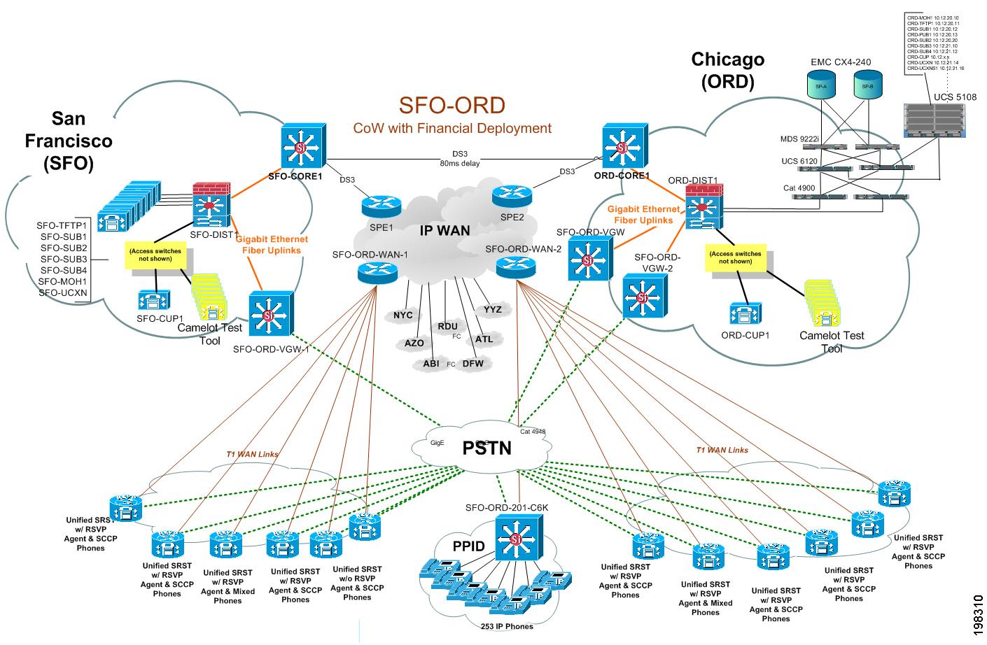
Figure 2 shows the Unified Computing System B-series Server chassis blade layout.
Figure 2 UCS B-series Server Chassis Blade Layout
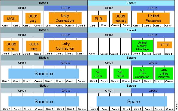
Table 2 lists the hardware and software components used in the Multisite Centralized, Clustering over the WAN with Unified SRST site model.
Very Large Campus with Clustering over the WAN
The Very Large Campus with Clustering over the WAN site model represents a very large campus in which two sites, San Jose (SJC) and Rockford (RFD), are used to cluster Cisco Unified Communications Manager over an IP WAN. This site also supports RSVP cluster.
The Cisco Unified Communications Manager cluster in this site model consists of the following:
•
•
•
•
This deployment model has the following characteristics:
•
•
•
•
•
•
•
•
•
•
•
Figure 3 shows the topology of the Very Large Campus with Clustering over the WAN site model.
Figure 3 Very Large Campus with Clustering over the WAN Site Model
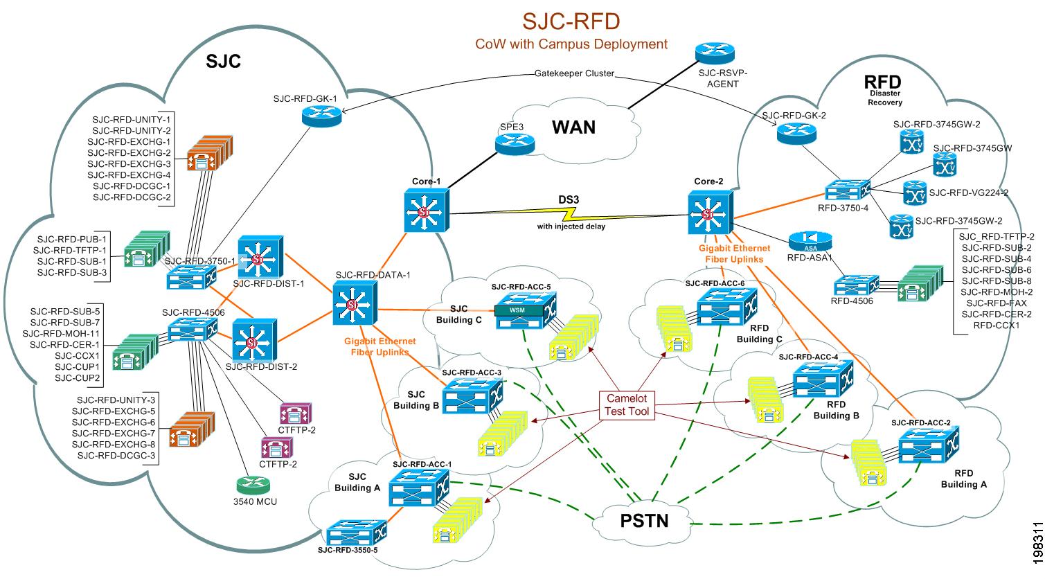
Table 3 lists the hardware and software components used in the Very Large Campus with Clustering over the WAN site model.
Large SIP Site
The Large SIP Site consists of one site called Dallas (DFW). This site includes a Cisco Unified Communications Manager cluster that includes the following:
•
•
•
The Large SIP Site model also includes Cisco Unity for voice messaging.
The site has 10,000 SIP endpoints and is setup with WAN connectivity to allow communication with other sites. Additionally, SIP gateways are used, to provide connectivity to the PSTN network
Figure 4 shows the topology of the Large SIP Site model.
Figure 4 Large SIP Site Topology
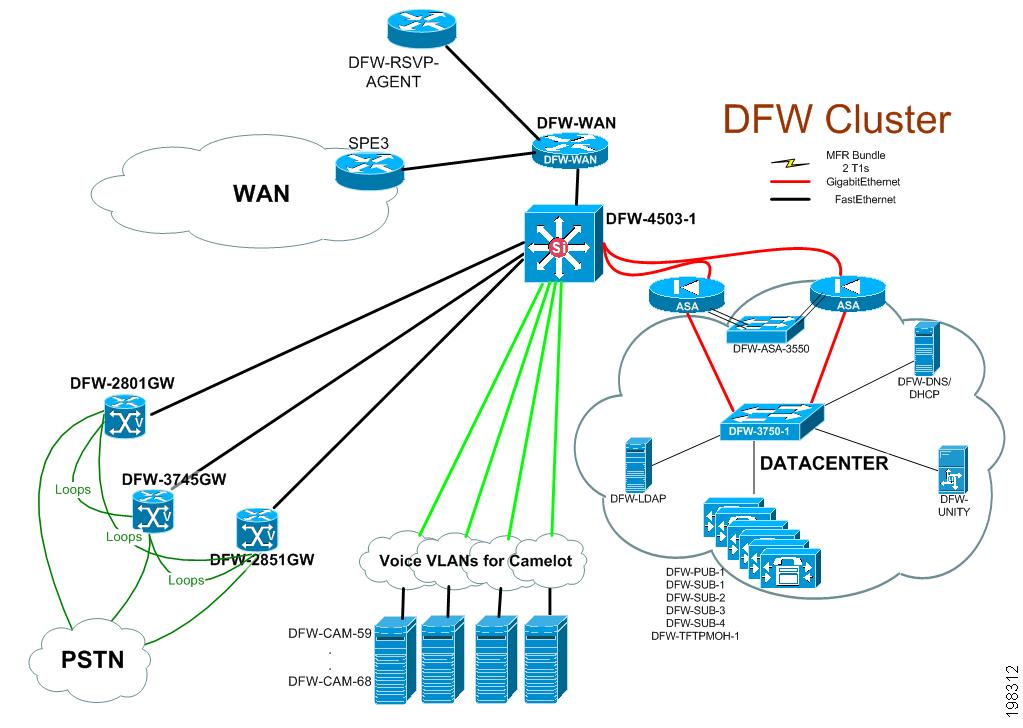
Table 4 lists the hardware and software components used in the Large SIP Site model.
Cisco Unified Communications Manager Business Edition Site with Unified SRST
The Cisco Unified Communications Manager Business Edition with Unified SRST site model with co-resident Cisco Unity Connection represents small to medium business deployments with remote sites over the IP WAN. The site is called Kalamazoo (AZO).
If either the central site or the IP WAN goes down, remote sites can continue to have service through Unified SRST running on Cisco IOS gateways. In addition, remote sites can place calls over the PSTN if the IP WAN becomes temporarily over-subscribed. The Unified SRST sites include H.323 and MGCP of 28xx and 38xx gateways. The WAN consists of T1 frame relay links.
The tested AZO site model has the following design characteristics:
•
•
•
•
Figure 5 shows the topology of the Cisco Unified Communications Manager Business Edition with Unified SRST site model.
Figure 5 Unified Communications Manager Business Edition with Unified SRST Topology
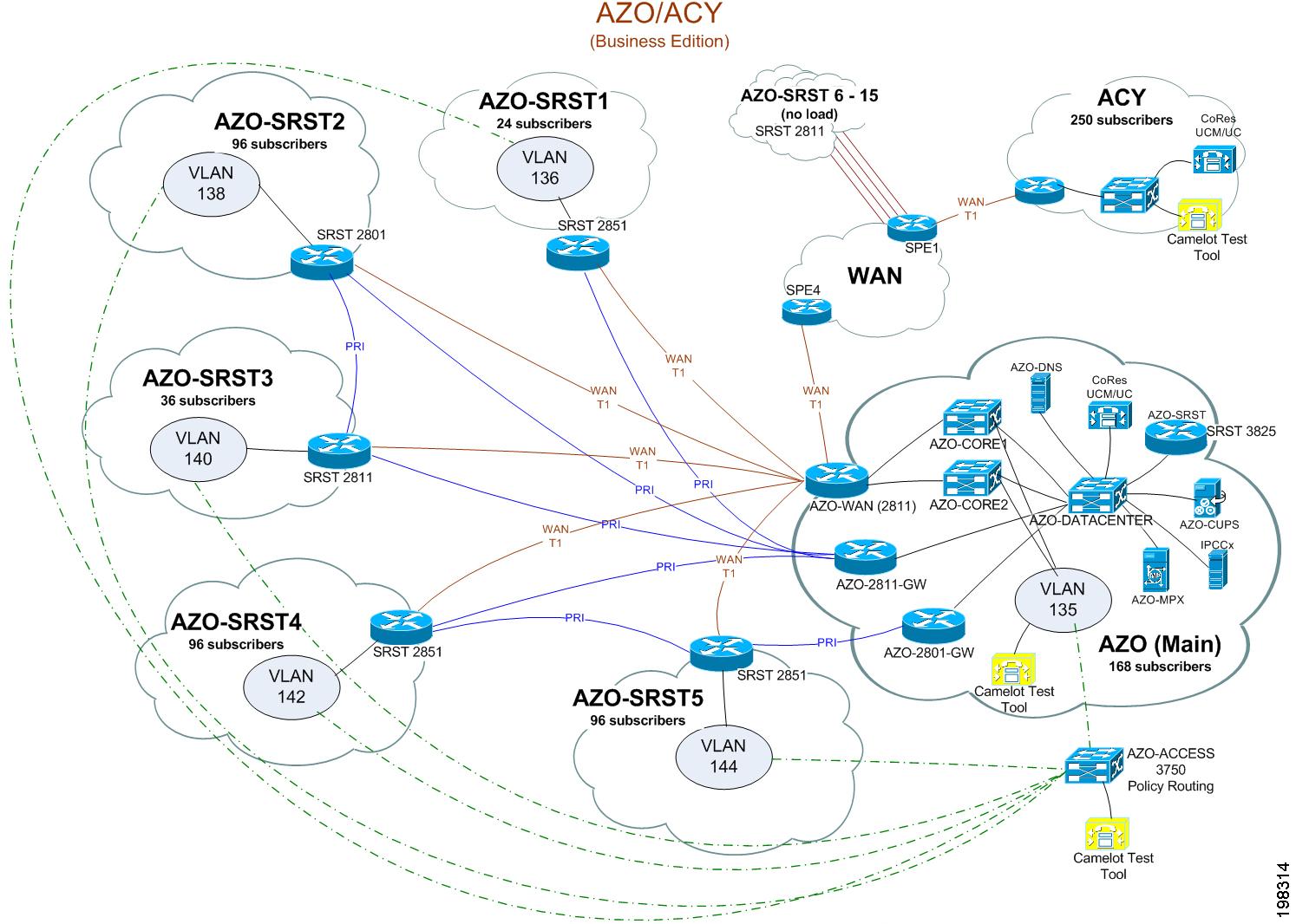
Table 5 lists the hardware and software components used in the Cisco Unified Communications Manager Business Edition with Unified SRST site model
Cisco Unified Communications Manager Business Edition Site
The Cisco Unified Communications Manager Business Edition with co-resident Cisco Unity Connection represents small to medium business deployments. This site is specifically used for testing InterCluster Trunk (ICT) calls to/from the Cisco Unified Communications Manager Business Edition Site with Unified SRST (AZO) cluster. The site is called Atlantic City (ACY).
Figure 5 shows the topology of the Cisco Unified Communications Manager Business Edition site model.
Small Campus SIP Unified Communications Manager Express Site
The Small-Campus SIP Site model consists of one site called Atlanta (ATL). This site includes:
•
•
This site communicates with Cisco Unified Communications Manager clusters in other sites using a SIP trunk through Cisco Unified Border Element (CUBE).
Figure 6 shows the topology of the Small-Campus SIP Site model.
Figure 6 Small -Campus SIP Site Topology
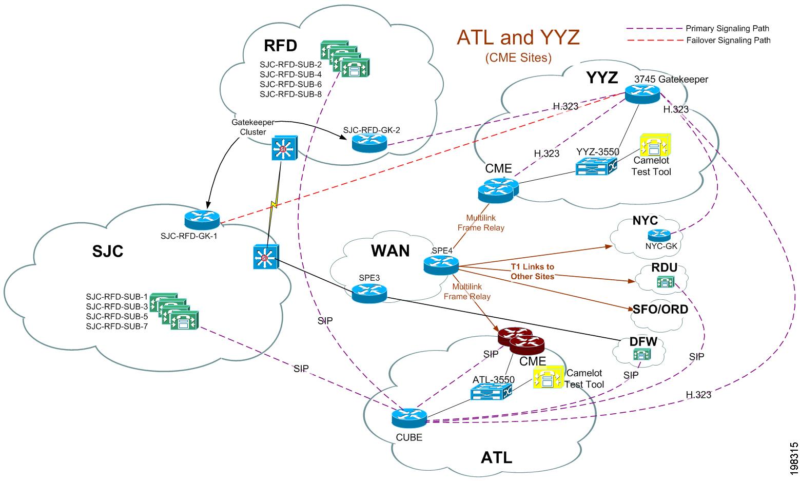
Table 7 lists the hardware and software components used in the Small-Campus SIP Site model.
Small Campus H.323 Unified Communications Manager Express Site
The Small-Campus H.323 Unified Communications Manager Express Site model consists of one site called Toronto (YYZ). This site includes:
•
•
•
The H.323 gatekeeper in YYZ provides the connectivity to other Cisco Unified Communications Manager clusters.
Figure 6 shows the topology of the Small-Campus H.323 Unified Communications Manager Express Site model.
Table 8 lists the hardware and software components used in the Small-Campus H.323 Unified Communications Manager Express Site model.
Cisco Unified Communications Manager Release 7.1(3) Interoperability Site
In the Cisco Unified Communications Manager Interoperability Site model for North America, one of the sites is called Raleigh (RDU). This site was designed to test interoperability between other Cisco Unified Communications Managers at version N with its own version at N-1.
•
•
This site supports a mix of 1000 SIP and SCCP endpoints.
Figure 7 shows the topology of this site.
Figure 7 Cisco Unified Communications Manager Release 7.1(3) Interoperability Site Topology
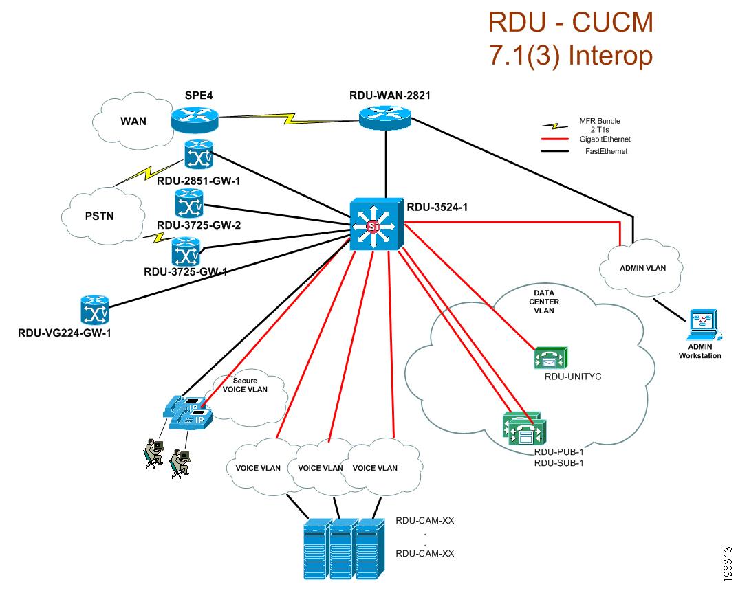
Table 9 lists the hardware and software components used in this model.
Cisco Unified Communications Manager Release 6.1(4) Interoperability Site
In the Cisco Unified Communications Manager Interoperability Site model for North America, one of the sites is called New York (NYC). This site was designed to test interoperability between other Cisco Unified Communications Managers at version N with its own version at N-2.
This site includes a Cisco Unified Communications Manager cluster that includes the following:
•
•
This site supports 1000 SCCP endpoints. Figure 8 shows the topology of this site.
Figure 8 Cisco Unified Communications Manager Release 6.1(4) Interoperability Site Topology
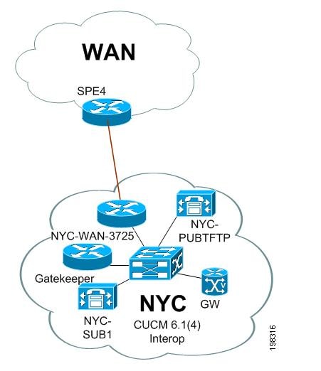
Table 10 lists the hardware and software components used in the Cisco Unified Communications Manager Release 6.1(4) Interoperability Site.
Cisco Unified Communications Manager - Session Manager Edition Site
The Cisco Unified Communications Manager - Session Manager Edition site model contains two sites, Kansas City (MCI) and Los Angeles (LAX), designed to simulate Session Management Edition of the Unified Communications 8.5 system train.
This cluster includes:
•
•
This deployment model has the following charcteristics:
•
•
•
•
•
•
•
•
Figure 9 shows the topology of this site:
Figure 9 Cisco Unified Communications Manager - Session Manager Edition (SME) Site Topology
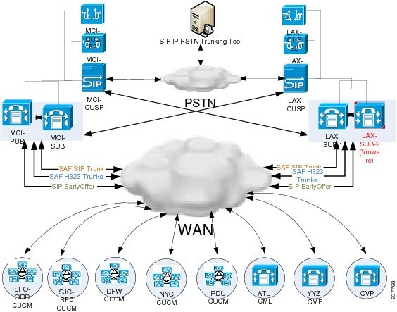
Table 11 lists the hardware and software components used in this model.
Europe and Emerging Markets Site Models
Eight site models were created and tested for Cisco Unified Communications Release 8.5(1) testing for Europe and Emerging Markets (EUEM) IP telephony. Each site model tested specific hardware and software components, features, functions, protocols, and related items.
A site model includes a site with a three-letter name (for example, CDG, GVA, and MAD). Examples throughout this manual refer to these site names.
The following sections describe each site model in detail. Each section includes an explanation of the design characteristics of the site model, and includes a table that lists the hardware and software components used in the model. The tables contain the following information for each component:
•
•
•
Table 12 lists the site models and references to sections that provide detailed information.
Table 12 EUEM Site Models
Paris (CDG)
Geneva (GVA)
Cisco Unified Communications Manager Session Management Edition
Co-located in Paris (CDG-SME and Co-located in Geneva (GVA-SME)
Brussels (BRU)
Madrid (MAD)
Cisco Unified Communications Manager Interoperability Site Centralized with Unified SRST
London (LGW)
Reykjavik (RKV)
Warsaw (WAW)
Manchester (MAN)
Bangalore (BLR)
For an illustration showing how these site models were deployed for testing, go to the Resource Library tab of the Technical Information Site.
Large Multisite Centralized with Unified SRST
The Large Multisite Centralized with Unified SRST site model consists of one site called Paris (CDG). This site model represents an international deployment with up to 21 remote sites deployed across various countries. It includes Cisco Unity Connection and third-party components. Cisco Unified Communications Manager uses QSIG, H.323, and SIP to interoperate between sites. Remote sites are interconnected through the WAN and all are RSVP-enabled to the central site. For Geneva (GVA) and Paris (CDG), inter cluster RSVP is enabled.
In this model, a Cisco Unified Communications Manager cluster serves 6000 phone in local and remote locations, with all endpoints and gateways fully encrypted (RTP and signalling). PBXs that support the QSIG ISO and QSIG ECMA variants connect to this cluster through direct QSIG links. The Cluster connects to the rest of the network through MPLS WAN networks.
Calls between the CDG site, the LGW site, and the MAD site are provided by H.323 intercluster trunks. Cisco Unity Connection provides voice messaging. PBX users access voice messaging features through the QSIG trunks to Cisco Unified Communications Manager.
Access to the PSTN for normal off-net calls is provided by ten E1 ETSI PRI links to the PSTN. Remote sites have either centralized breakout to the PSTN or local PSTN breakout using E1 PRI, BRI, or FXO connections. PSTN access is controlled by Cisco Unified Communications Manager using MGCP, H.323, or SIP. Unified SRST is used in each remote site.
Access to the SIP network is provided through a SIP trunk to a remote Cisco Unified SIP Proxy (CUSP). Access to third-party services such as operator console, if available, is provided locally. Some of the sites will also have video endpoints and Cisco Unified Videoconferencing Gateways, and remote QSIG PBXs.
Cisco Unified Communications Integration™ for Microsoft Office Communicator and Cisco Unified Presence Server are tested as part of this site model. Cisco Unified Communications Integration™ for Microsoft Office Communicator provides interoperability with Microsoft Office Communicator Server 2007 (OCS) R2 version with Microsoft Office Communicator (MOC) clients.
The Large Multisite Centralized with Unified SRST site model have these design characteristics:
•
•
•
•
•
•
•
•
•
•
•
•
•
•
•
•
•
•
Figure 10 shows the topology of the Large Multisite Centralized with Unified SRST Site model.
Figure 10 Large Multisite Centralized with Unified SRST Site Topology
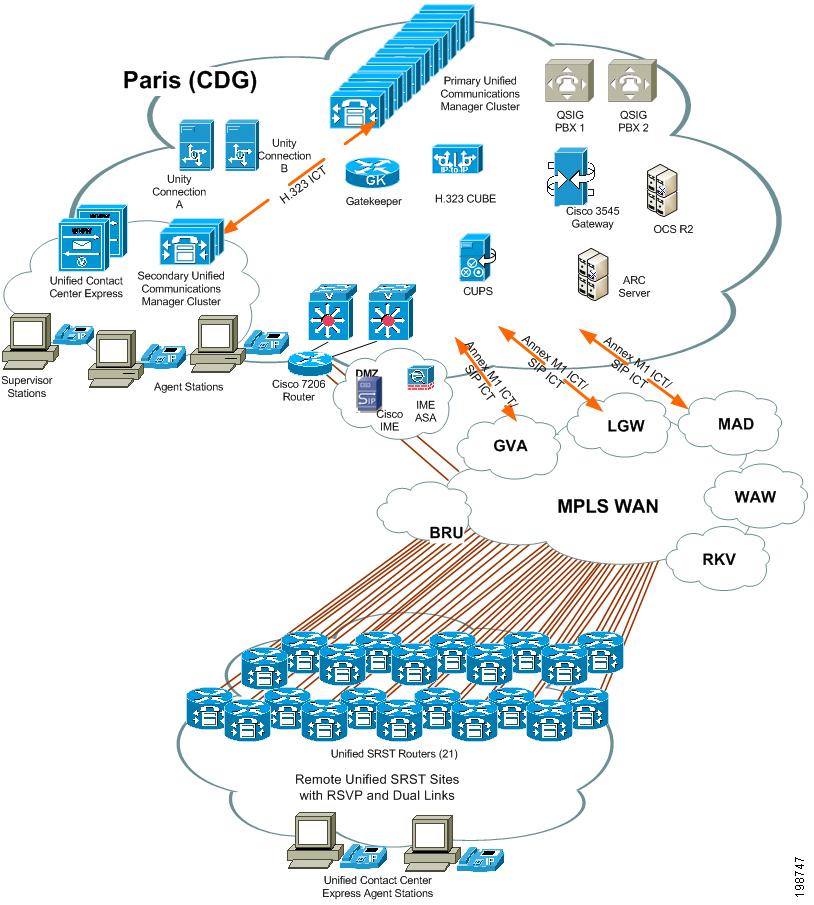
Table 13 lists the hardware and software components used in the Multisite Centralized, Clustering over the WAN with Unified SRST site model.
Table 13 Large Multisite Centralized with Unified SRST Site Model Components
Datacenter Catalyst switch
WS-C6509-E
3
Analog gateway
Cisco ATA 187 Analog Telephone Adaptor
3
Cisco Unified Communications Manager server
Cisco MCS 7835 Unified Communications Manager Appliance
131
Firewall-ASA
Data center - 5510
1
Cisco IME - 5520
1
Cisco Unified SRST routers
Cisco 2801
4
Cisco 2811
3
Cisco 2821
3
Cisco 2851
4
Cisco 3825
3
Cisco 3845
3
Cisco 7200
1
Cisco Unified Contact Center Express
Cisco MCS 7835 Unified Communications Manager Appliance
2
Cisco Unified IP Phone
Cisco Unified IP Phone 7971G-GE
10
Cisco Unified IP Phone 7970G
10
Cisco Unified IP Phone 7961G/7961G-GE
5
Cisco Unified IP Phone 7941G/7941G-GE
5
Cisco Unified IP Phones models 6921, 6941, 6961
5
Cisco IP Communicator
2
Cisco Unified Communications Integration™ for Microsoft Office Communicator
6
Cisco Unified Personal Communicator
2
Cisco Unified IP Phones models 8961
5
Cisco Unity Connection
Cisco MCS 7845 Unified Communications Manager Appliance
2
Core Catalyst chassis
WS-C6506-E
2
E1 gateway card
Cisco 3845
1
Gateway
Cisco 2801
2
Cisco 2811
2
Cisco 2821
2
Cisco 2851
2
Cisco 3825
2
Cisco 3845
2
PSTN Gateway
Cisco 3845
3
Access switch
WS-C3550-24PWR-SMI
3
WS-C3750-24PS-S
3
WS-C3750-48PS-S
2
Router
Cisco 7206-VXR
1
Video conferencing
Cisco Unified Videoconferencing MCU 3545
2
Video endpoint
Cisco Unified Video Advantage
4
Cisco IP Phone 7985
5
Cisco Unified IP Phones models 9951and9971
5
Video H.320 Gateway BRI
IPVC-3521-GW-4B
2
Video H.320 Gateway PRI
IPVC-3526-GW-1P
2
Video MCU and Gateway
IPVC-3545-CHAS
1
1 Divided into two Unified Communications Manager clusters: one main cluster consisting of 11 servers and a second smaller cluster of two servers supporting the Unified Contact Center Express server and agent phones.
Medium Site Centralized with Unified SRST
The Medium Site model consists of one centralized site with three SRST remote sites called Geneva (GVA). In this model, a Cisco Unified Communications Manager cluster serves 2000 phones. The Cisco Unified Communications Manager cluster connects to the rest of the network through MPLS WAN networks.
A local Cisco Unity Connection provides voice messaging services for local PBX and Cisco Unified Communications Manager users. Access to the PSTN for normal off-net calls is provided by five E1 RTSI PRI links to the PSTN. Access to other sites and to services such as Cisco Unified MeetingPlace Express is provided by H.323 gatekeeper controlled trunks and an IP-to-IP gateway. Access to the SIP network is through a SIP trunk to a remotely located Cisco Unified SIP Proxy (CUSP). Third-party operator consoles are provided on Cisco Unified Communications Manager to serve local phones and to provide backup to the operator console in the CDG site.
The Medium Site model has these design characteristics:
•
•
•
•
•
•
•
•
•
•
•
•
•
Figure 11 shows the topology of the EUEM Medium Site model (GVA).
Figure 11 EUEM Medium Site Topology
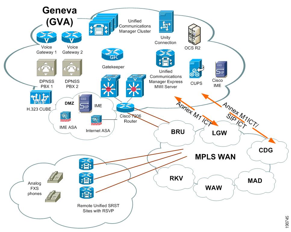
Table 14 lists the hardware and software components used in the Medium Site model.
Cisco Unified Communications Manager Session Management Edition
The Cisco Unified Communications Manager Session Management Edition deployment is a variation of multisite distributed call processing deployments model, which interconnects large numbers of Cisco Unified Communcations systems. In the EUEM sites, the Unified CM Session Management Edtion deployments consists of two sites: Paris (CDG-SME) and Geneva (GVA-SME).
In this deployment there are two Unified CM-SME clusters namely CDG-SME cluster and GVA-SME cluster, CDG-SME cluster is co-located with CDG site and aggregates trunks (SIP, H.323, QSIG, and QSIG over SIP) from the CDG leaf node, MAD eaf node and LGW leaf node. The GVA-SME cluster is co-located with GVA site and aggregates trunks (SIP, H.323, QSIG, and QSIG over SIP) from the GVA leaf node, RKV leaf node and Brussels leaf node.
CDG-SME cluster and its leaf nodes (CDG, CDG-remotes, MAD) are running in the SAF Autonomous system 333 and GVA-SME cluster and its leaf nodes (GVA, RKV, Brussels) are running in the SAF Autonomous system 444, at present we have NOT enabled static re-distribution between the two SAF ASs'.
Cisco Unity Connection server provides voice mail services to Unified CM, Unified CM-SME, and remote users.
Service Advertisement Framework (SAF) and Session Management Edition (SME) Setup: SAF allows networking applications to discover the existence, location, and configuration of networked services (Call Control Discovery) within networks by using the underlying network as a transport for service advertisements
Cisco Unified CM Session Management Edition: CUCM-SME is essentially a Unified CM clusters supporting a large number of trunk interfaces and enables the aggregation of multiple UC systems using multiple trunk types for voice, video and fax calls
The focus of SAF testing for Fairborn release is centered on combining the CUCM-SME (Centralized Architecture) and SAF (Distributed Architecture)
Paris (CDG-SME) site
The CDG-SME cluster consists of CDG leaf cluster (Unified CM servers), Cisco Unity Connection server, Gateways and Gatekeepers. The CDG-SME cluster is connected to MAD leaf cluster through a QSIG SIP trunk and to the LGW leaf cluster through H.323 Annex M1 trunks. There are two QSIG SIP trunks configured between CGD leaf and CDG-SME cluster and also between CDG-SME and MAD leaf cluster. One of the SIP trunks is a SAF enabled SIP trunk and the other is a static SIP trunk.
When a call is made from CDG (leaf) to MAD (leaf) via CDG-SME cluster, first leg from CDG (leaf) to CDG-SME cluster will be SAF trunk and second leg from CDG-SME cluster to MAD (leaf) will be static SIP (QSIG) trunk.
The CDG-SME cluster Site model has these design characteristics:
•
•
•
•
•
•
•
•
Geneva (GVA-SME) site
The GVA-SME cluster consists of GVA leaf cluster (Unified CM servers), Cisco Unity Connection server, Gateways and Gatekeepers. The GVA-SME cluster is connected to RKV leaf through SAF enablaed SIP trunks and to the BRU leaf through both statis SIP trunk and SAF enabled SIP trunk.
The GVA-SME cluster Site model has these design characteristics:
•
•
•
•
•
•
•
•
•
Figure 12 shows the topology of the Unified Communications Manager Session Management Edition depolyment model (EUEM site)
Figure 12 Unified Communications Manager Session Management Edition deployment model (EUEM) site Topology
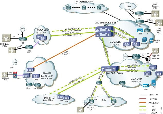
Table 15 lists the hardware and software components used in the Unified Communications Manager Session Management Edition depolyment model (EUEM site).
Medium Site Dual-stack Centralized with Unified SRST
The Medium Site Dual-stack Centralized with Unified SRST (Brussels-BRU) consists of one site called Brussels (BRU). In this model, two servers—Cisco Unified Communications Manager Linux based Unified CM clusters serve 1000 phone users in both local and remote locations.
A separate Cisco Network Registrar (CNR) server is used to provide DHCP IPv4/IPv6 addressing for the central site. It also acts as the DNS IPv6 and IPv4 for both the central and remote sites. This cluster is connected to the rest of the network through MPLS WAN networks.
Calls between this site and other sites (LGW and MAD) sites are made through the WAN with Annex M1 Inter Cluster Trunks. All the internal calls within the site are G.711 and all calls between sites are G.729.
Cisco Unity Connection server provides voice mail services to both Unified CM and remote users. Access to the PSTN for normal "off-Net" calls is provided by E1 ETSI PRI links to the PSTN.
The three remote sites are connected through a WAN link and they have location based CAC to the central site. PSTN access for these remote sites either have centralized breakout to the PSTN, or local PSTN breakout using E1 PRI, BRI, or FXO connections and are controlled by Unified CM using either MGCP, H.323, or SIP. Unified SRST is used in each remote site.
Some of the phones have security encryption. VG224 acts as dual-stack gateways and Cisco 2851 acts as analog SCCP gateway.
The LAN infrastructure of this site includes CAT4500 as distribution/core switch and Cisco 3750 and Cisco 3560 as access switches and both of them are dual-stack components.
The MTP component provides media stream conversion from IPv4 to IPv6 and vice versa. The CE router and the MTP component share the same hardware—Cisco 3845.
The CE router and the remote ISRs provides IPv6 to IPv4 tunneling over the WAN. One of the SRST remote has been enabled with HSRPv6 (active-active) and DHCPv6.
The Medium Site Dual-stack Centralized with Unified SRST (Brussels-BRU) Site model has these design characteristics:
For BRU Central Site:
•
•
•
•
•
•
•
•
•
•
For BRU Remote:
•
•
•
•
•
Figure 13 shows the topology of the EUEM Small Site model.
Figure 13 Medium Site Dual-stack Centralized with Unified SRST Topology
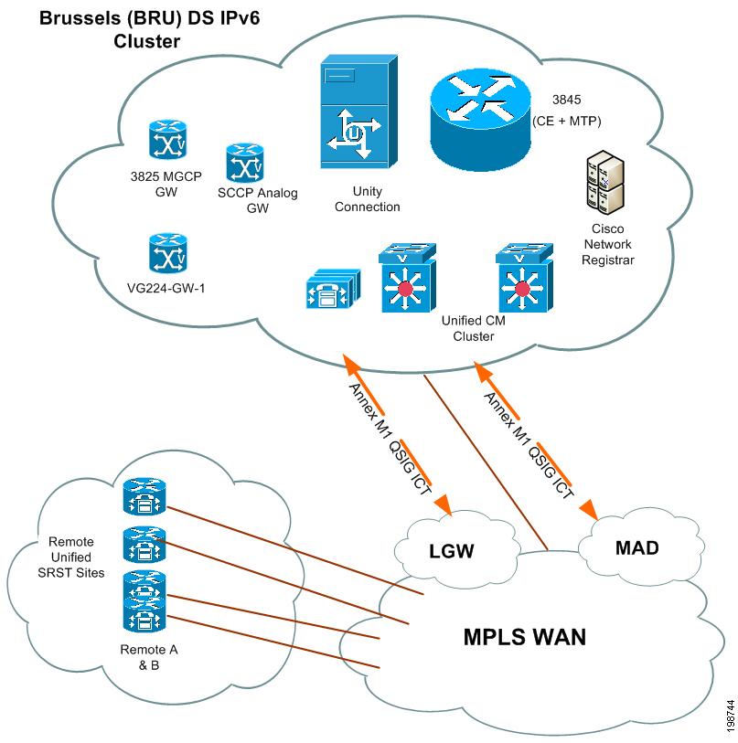
Table 16 lists the hardware and software components used in the Medium Site Dual-Stack Centralized with Unified SRST model.
Small Site (MAD)
The Small Site model for Europe and Emerging Markets consists of one site called Madrid (MAD). In this model, a Cisco Unified Communications Manager cluster serves 750 phones in a single campus. A PBX that supports the ISO QSIG variant connects to this cluster through direct QSIG links.
Cisco Unity Connection connects to the cluster through the QSIG-enabled intercloster trunk via the LGW site and provide voice messaging functions to PBX users and to Cisco Unified Communications Manager users. PBX users have access to Cisco Unified Communications Manager through a QSIG trunk.
The Cluster connects to the rest of the network through MPLS WAN networks. Calls between this site and other sites in the network are made through the WAN with two Annex M1 intercluster trunks to the CDG and LGW sites.
Access to the PSTN as a backup route to other sites and for normal off-net calls is provided by two E1 ETSI PRI links to the PSTN.
The Small Site model has these design characteristics:
•
•
•
•
•
•
•
•
•
Figure 14 shows the topology of the EUEM Small Site model.
Figure 14 EUEM Small Site Topology
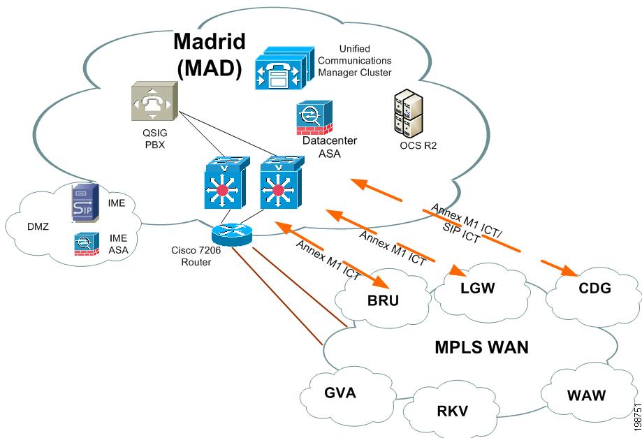
Table 17 lists the hardware and software components used in the EUEM Small Site model.
Cisco Unified Communications Manager Interoperability Site Centralized with Unified SRST
The Cisco Unified Communications Manager Interoperability Site model for EUEM consists of one site called London (LGW). In this model, a Cisco Unified Communications Manager cluster serves 2,000 phones in a single campus. A PBX that supports the ISO QSIG variant connects to this cluster through direct QSIG links.
The Cluster connects to the rest of the network through MPLS WAN networks. Calls between this site and other sites in the network are made through the WAN with two Annex M1 intercluster trunks to the CDG and MAD sites.
Some PBX and Cisco Unified Communications Manager users have voice messaging services provided by Cisco Unity Connection, which is connected to the cluster through an SCCP link. The PBX user access voice messages through QSIG trunks to Cisco Unified Communications Manager.
Other PBX and CCM users have access to voice messaging with Unity Connection located in the CDG Site via the Annex M1 Inter Cluster Trunk. MWI events and message store and retrieval for both the connected PBX and the CCM users is all passed Annex M1 between the sites.
Access to the PSTN as a backup route to other sites and for normal off-net calls is provided by 5 E1 ETSI PRI links to the PSTN. Access to the Cisco Unified Communications Manager network, and any non-directly connected clusters is provide through remotely located H.323 gatekeepers. Access to the SIP network is provided through a SIP trunk to a remotely located Cisco Unified SIP Proxy (CUSP). Operator console services are provided locally
The Cisco Unified Communications Manager Interoperability Site model has these design characteristics:
•
•
•
•
•
•
•
•
Figure 15 shows the topology of the EUEM Cisco Unified Communications Manager Interoperability site model.
Figure 15 EUEM Cisco Unified Communications Manager Interoperability Site Topology
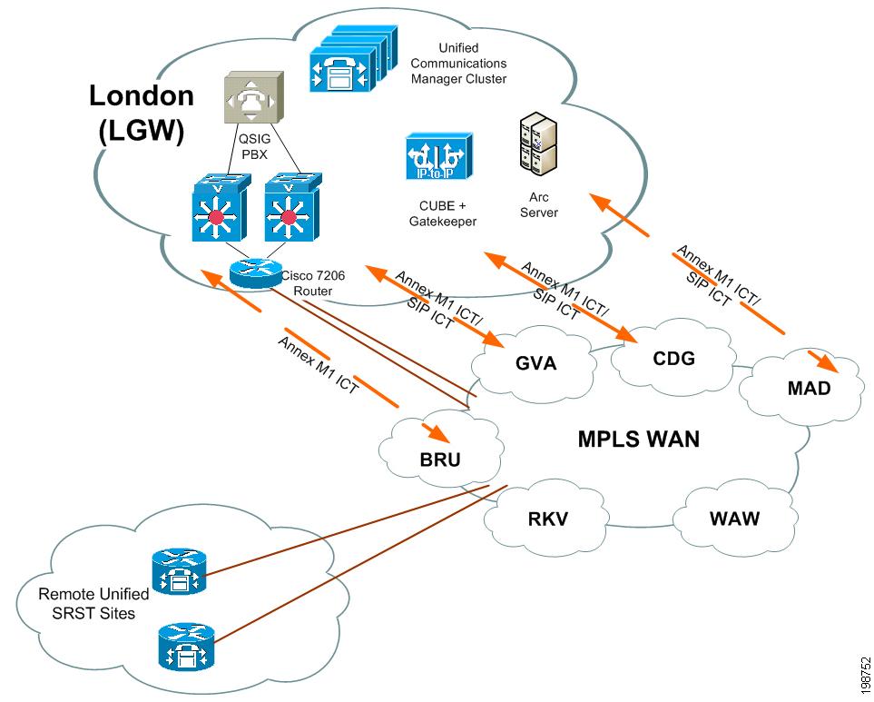
Table 18 lists the hardware and software components used in the EUEM Cisco Unified Communications Manager Interoperability Site model.
Cisco Unified Communications Manager Interoperability Site (Cisco SIP CME Site Aggregated by Cisco Unified SIP Proxy)
The Small Campus SIP only Multisite model consists of one site called Reykjavik (RKV). This model includes three Cisco Unified Communications Manager Express (Unified CME) sites aggregated by a Cisco Unified SIP Proxy (CUSP) module running on a Cisco 3825 gateway router. The Cisco Unified SIP Proxy is a high-performance, highly available stateless Session Initiation Protocol (SIP) server for centralized routing and SIP signaling normalization. Each Unified CME is connected to Cisco Unified SIP Proxy module through SIP trunks. The Cisco Unified SIP Proxy is connected to other Unified Communications Manager clusters in CDG and GVA sites through SIP trunks. SIP RSVP features are configured on the Unified CME routers for RSVP between Unified CME phones and Unified CM cluster phones.
The Small Campus SIP only Multisite model has these design characteristics:
•
•
•
Figure 16 shows the topology of the Non-Cisco Unified Communications Manager Interoperability Site model.
Figure 16 Non-Cisco Unified Communications Manager Interoperability Site Topology
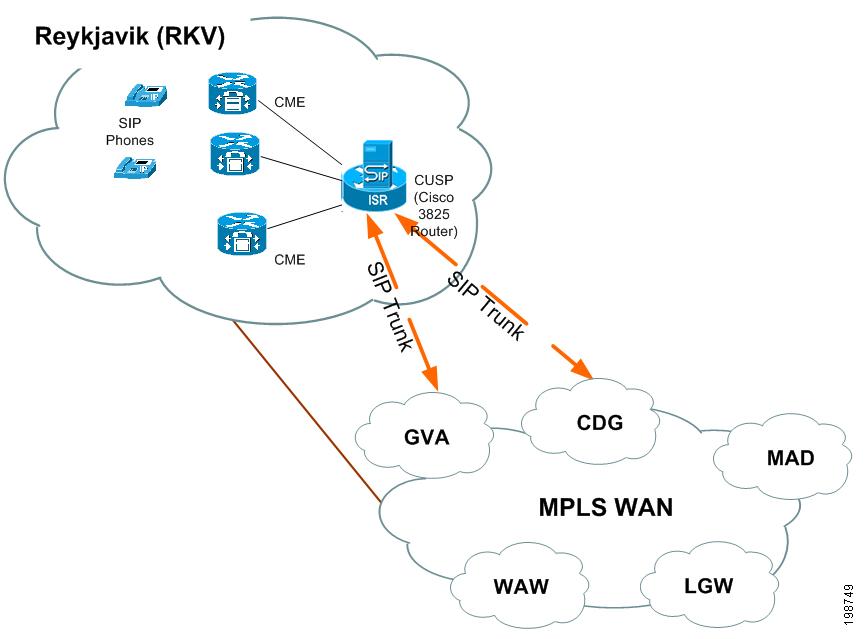
Table 19 lists the hardware and software components used in the Non-Cisco Unified Communications Manager Interoperability Site model.
Small Campus Multisite H.323
The Small Campus Multisite H.323 site model consists of one site called Warsaw (WAW). This model includes 13 Cisco Unified Communications Manager Express sites connected to each other and to the rest of the network through H.323 gatekeepers. Each Cisco Unified Communications Manager cluster uses an IP-to-IP gateway and MTP to communicate with the Cisco Unified Communications Manager Express systems in this site.
Each Cisco Unified Communications Manager Express system has either Cisco Unity Express installed locally, or will access Cisco Unity Connection through an MWI relay gateway that is located in the GVA site.
The Small Campus Multisite H.323 model has these design characteristics:
•
•
•
•
Figure 17 shows the topology of the Small Campus Multisite H.323 site model.
Figure 17 Small Campus Multisite H.323 Site Topology
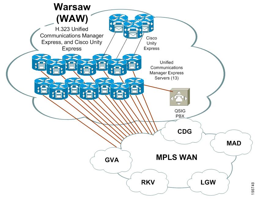
Table 20 lists the hardware and software components used in the Small Campus Multisite H.323 model.
Mid-Market Multi-Site Centralized (Unified CMBE)
The Mid-Market Multi-Site Centralized cluster consists of one centralized site with five SRST remote sites called Manchester (MAN). This model includes Cisco Unified Communications Manager and Cisco Unity Connection running on co-resident deployment on a single Cisco MCS 7828 Unified Communications Manager Appliance server. A separate Windows 2008 server acts as the DNS server for both central and remote sites. DHCP is provided by the remote and central Cisco ISRs.
In this model, a Cisco Unified Communications Manager cluster serves 500 phone users in local and remote locations, with the Cisco Unity Connection in the central site providing the voice mail services. Operator console (CUBACS) is provided separately on a local server in the central site.
The Central site is connected to the remote SRST sites through MPLS WAN networks. All calls within central site or within remote sites are G.711 and calls between remote sites and central site are G.729a with 30 ms packetisation period. If the Unified Communications Manager in central site goes down, all central site phones will re-register to a SRST router in central site and all remote site phones will register to the corresponding remote site SRST routers.
Access to the PSTN for normal "off-Net" calls is provided by E1 ETSI PRI/BRI links to the PSTN. The five remote sites are connected through WAN network and have RSVP setup for CAC to the central site. PSTN access for these remote sites either have centralized breakout to the PSTN, or local PSTN breakout using E1 PRI, BRI, or FXO connections and are controlled by Unified CM using either H.323 or SIP.
Central site uses MGCP PRI for Central PSTN.
The Mid-Market-Multi-Site Centralized site model has these design characteristics:
•
•
•
•
•
•
•
•
Figure 18 shows the topology of the Mid-Market-Multi-Site Centralized site model.
Figure 18 Mid-Market Multi-Site Centralized Site Topology

Table 21 lists the hardware and software components used in the Mid-Market Multi-Site Centralized site model.
Mid-Market Multi-Site Centralized (Unified CMBE 3000)
The Mid-Market Multi-Site Centralized (Unified CMBE3000) consists of one centralized site called Bangalore (BLR) with two remote sites. This model includes Cisco Unified Communications Manager Business Edition on a single Cisco MCS 7816-I5 Appliance server. A separate Windows 2008 server acts as the DNS server for both central and remote sites. DHCP is provided by the remote and central Cisco ISRs.
In this model, a Cisco Unified Communications Manager Business Edition serves 300 users in local and remote locations.
The Central site is connected to remote sites through MPLS WAN. A Cisco 2901 gateway in the central site acts as a centralized break out to PSTN through E1 PRI. There are no local PSTN breakouts in this release. This gateway also acts as the transcoding and conference resource.
The Mid-Market-Multi-Site Centralized (Unified CMBE 3000) site model has these design characteristics:
•
•
•
•
•
Figure 19 shows the topology of the Mid-Market-Multi-Site Centralized (Unified CMBE 3000) site model.
Figure 19 Mid-Market-Multi-Site Centralized (Unified CMBE 3000) Site Topology
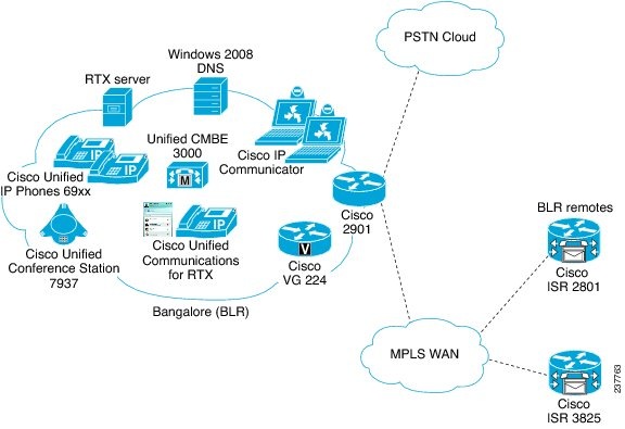
Table 22 lists the hardware and software components used in the Mid-Market Multi-Site Centralized (Unified CMBE 3000) site model.
 Feedback