Tested Deployments and Site Models
Available Languages
Table Of Contents
Tested Deployments and Site Models
Multi-Site Distributed Deployment Options
Multi-site Centralized, Clustering over the WAN with Unified SRST
Very Large Campus with Clustering over the WAN
Cisco Unified CallManager Interoperability Site (North America)
Non-Cisco Unified CallManager Interoperability Site (North America)
Europe and Emerging Markets Site Models
Large Multi-Site Centralized with Unified SRST
Cisco Unified CallManager Interoperability Site (Europe and Emerging Markets)
Non-Cisco Unified CallManager Interoperability Site (EUEM)
Tested Deployments and Site Models
Cisco Unified Communications Release 5.0 testing for IP telephony was designed to test the hardware and software components that work together in a multi-site distributed IP telephony deployment.
For this testing, the following site models were created. Each site model was designed to test a specific set of features and interactions. The site models can be used in various combinations to create different versions of a multi-site distributed deployment model.
•
North America site models:
–
–
–
–
–
–
–
–
–
•
–
–
–
–
–
–
This chapter describes each site model.
For additional guidelines, recommendations, and best practices for implementing enterprise networking solutions, refer to the Cisco Solution Reference Network Design (SRND) guides and related documents, which are available at this URL:
For a list of the release versions of the components used in the site models, see Appendix A, "Release Versions of Components."
This topic includes the following sections:
•
•
Purpose of Solution Tests
An efficient, effective, and reliable IP telephony solution requires many interrelated hardware and software components. The site models that are described in this manual provide you with models and guidance as you implement an IP telephony system for your organization. Cisco has selected, installed, configured, and tested hardware and software designed to work together seamlessly and to provide a complete and optimized IP telephony solution.
Each site model addresses some or all of the following issues:
•
•
•
•
•
•
•
•
•
•
•
•
•
•
Multi-Site Distributed Deployment Options
The site models within each test group (North America and EUEM) can be implemented in various combinations to create deployment models to meet the needs of a wide range or organizations.
Figure 1-1 shows the multi-site distributed deployment that was tested for Cisco Unified Communications Release 5.0 testing for North America IP telephony.
For more detailed information about the sites used in this deployment, see the "North America Site Models" section.
Figure 1-1 Multi-Site Distributed Deployment for North America IP Telephony
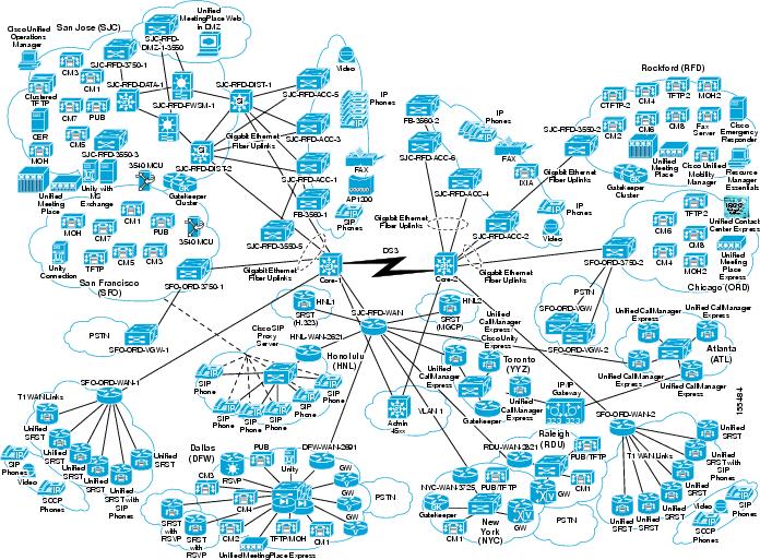
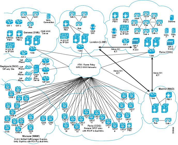
Figure 1-2 shows the multi-site distributed deployment that was tested for Cisco Unified Communications Release 5.0 testing for EUEM IP telephony.
For more detailed information about the sites used in this deployment, see the "Europe and Emerging Markets Site Models" section
Figure 1-2 Multi-Site Distributed Deployment for EUEM IP Telephony
North America Site Models
Nine site models were created and tested for Cisco Unified Communications Release 5.0 testing for North America IP telephony. Each site model tested specific hardware and software components, features, functions, protocols, and related items.
A site model includes one or more sites. Each site has a three-letter name (for example, SFO, ORD, and SJC). Examples throughout this manual refer to these site names.
The following sections describe each site model in detail. Each section includes an explanation of the design characteristics of the site model, and includes a table that lists the hardware and software components used in the model. The tables contain the following information for each component:
•
•
•
Table 1-1 lists the site models and references to sections that provide detailed information.
Table 1-1 North America Site Models
Multi-site Centralized, Clustering over the WAN with Unified SRST
San Francisco (SFO), Chicago (ORD)
San Jose (SJC), Rockford (RFD), Honolulu 1(HNL1), Honolulu 2 (HNL2)
Dallas (DFW)
Raliegh (RDU)
Atlanta (ATL)
Toronto (YYZ)
Cisco Unified CallManager Interoperability Site (North America)
New York (NYC)
Non-Cisco Unified CallManager Interoperability Site (North America)
Honolulu (HNL)
San Jose (SJC)
Multi-site Centralized, Clustering over the WAN with Unified SRST
The Multi-site Centralized, Clustering over the WAN with Unified SRST site model represents a deployment in which two sites, San Francisco (SFO) and Chicago (ORD), are used to cluster Cisco Unified CallManager over an IP WAN. In this model, half of the cluster resides in SFO and the other half in ORD. These sites provide centralized call processing to remote Cisco Unified Survivable Remote Site Telephony (Unified SRST) sites. Communications with remote sites takes place over the IP WAN.
If either the central site or the IP WAN goes down, remote sites can continue to have service through Unified SRST) running on Cisco IOS gateways. In addition, remote sites can place calls over the PSTN if the IP WAN becomes temporarily oversubscribed.
SFO and ORD sites are the hub site for remote Unified SRST sites. Unified SRST sites include H.323 and MGCP 26xx, 28xx, 37xx, 38xx and 72xx gateways. The WAN consists of T1 frame relay links.
The tested Multi-Site Centralized has the following design characteristics:
•
•
•
•
•
•
•
•
•
•
•
Figure 1-3 provides an overview of the Multi-site Centralized, Clustering over the WAN with Unified SRST site model.
Figure 1-3 Multi-site Centralized, Clustering over the WAN with Unified SRST Site Model
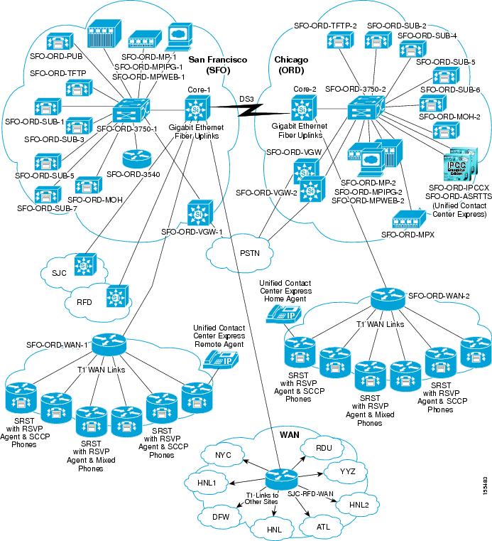
Table 1-2 lists the hardware and software components used in the Multi-site Centralized, Clustering over the WAN with Unified SRST site model.
Very Large Campus with Clustering over the WAN
The Very Large Campus with Clustering over the WAN site model represents a very large campus in which two sites, San Jose (SJC) and Rockford (RFD), are used to cluster Cisco Unified CallManager over an IP WAN. This site model also includes the Honolulu 1 (HNL1) and Honolulu 2 HNL2 sites, which provide Unified SRST capabilities and which are managed by the Cisco Unified CallManager cluster.
The Cisco Unified CallManager cluster in this site model consists of the following:
•
•
•
•
•
This deployment model has the following characteristics:
•
•
•
•
•
•
•
•
Figure 1-4 shows the topology of the Very Large Campus with Clustering over the WAN site model.
Figure 1-4 Very Large Campus with Clustering over the WAN Site Model
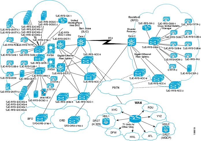
Table 1-3 lists the hardware and software components used in the Very Large Campus with Clustering over the WAN site model.
Large SIP Site
The Large SIP Site consists of one site called Dallas (DFW). This site includes a Cisco Unified CallManager cluster that includes the following:
•
•
•
•
The Large SIP Site model also include EPAS (Cisco Unified Presence Server, proxy server, intermediate path performance monitoring), Unified SRST for SIP, Cisco Unity Connection for voice messaging, and Cisco Unified MeetingPlace Express for audio conferencing.
WAN connectivity is provided by a Cisco 2691 router and two SIP gateways provide connectivity to PSTN network. This site has 10,000 SIP endpoints.
Figure 1-5 shows the topology of the Large SIP Site model.
Figure 1-5 Large Sip SiteTopology
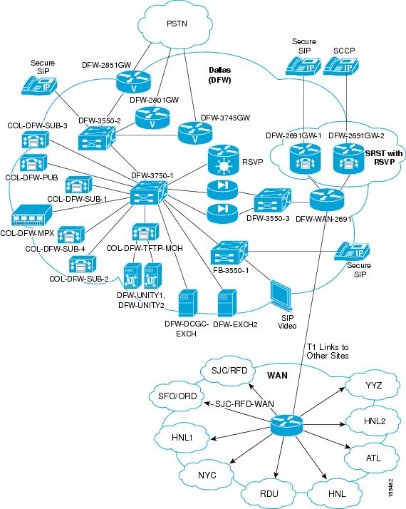
Table 1-4 lists the hardware and software components used in the Large SIP Site site model.
Small Site (North America)
The Small Site model for North America consist of one site called Raliegh (RDU). This site includes a Cisco Unified CallManager cluster that includes the following:
•
•
The Small Site model supports 1,000 phones.
Figure 1-6 shows the topology of the Small Site model.
Figure 1-6 Small Site Topology
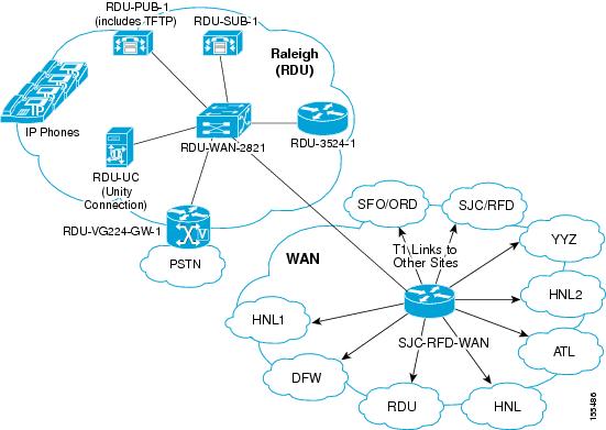
Table 1-5 lists the hardware and software components used in the Small Site model.
Small-Campus SIP Site
The Small-Campus SIP Site model consists of one site called Atlanta (ATL). This site includes:
•
•
•
This site communicates with Cisco Unified CallManager clusters in other sites using a SIP trunk through an IP-to-IP gateway.
Figure 1-7 shows the topology of the Small-Campus SIP Site model.
Figure 1-7 Small -Campus SIP Site Topology
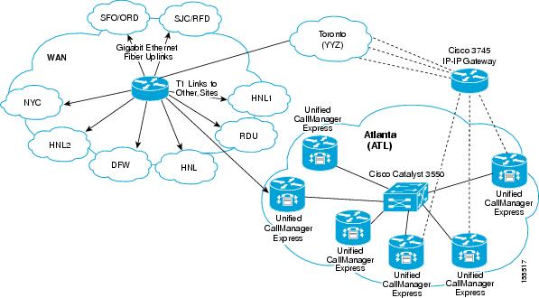
Table 1-6 lists the hardware and software components used in the Small-Campus SIP Site model.
Small-Campus H.323 Site
The Small-Campus H.323 Site model consists of one site called Toronto (YYZ). This site includes:
•
•
•
The Cisco Unified CallManager Express routers connect to MP 5.3 via the H.323 gatekeeper.
This site has four hundred SCCP endpoints. An IP-to-IP gateway between YYZ and ATL provides connectivity between Cisco Unified CallManager Express routers and Cisco Unified CallManager clusters. The H.323 gatekeeper provides connectivity between Cisco Unified CallManager Express routers and Cisco Unified CallManager clusters.
Figure 1-8 shows the topology of the Small-Campus H.323 Site model.
Figure 1-8 Small-Campus H.323 Site Topology
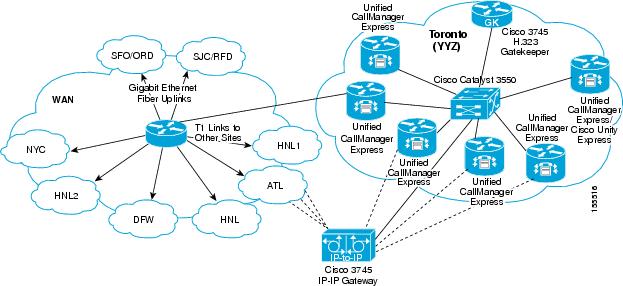
Table 1-7 lists the hardware and software components used in the Small-Campus H.323 Site model.
Cisco Unified CallManager Interoperability Site (North America)
The Cisco Unified CallManager Interoperability Site model for North America consists of one site called New York (NYC). This site was designed to test interoperability between Cisco Unified CallManager 4.1(3) SR1and Cisco Unified CallManager 5.0.
This site includes a Cisco Unified CallManager cluster that includes the following:
•
•
This site also has one Cisco Emergency Responder server, one VG224 with 24 analog phones, sic SCCP phones, and 600 simulated SCCP phones.
Figure 1-9 shows the topology of the Cisco Unified CallManager Interoperability Site model.
Figure 1-9 Cisco Unified CallManager Interoperability Site Topology
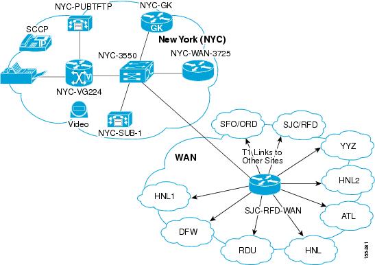
Table 1-8 lists the hardware and software components used in the Cisco Unified CallManager Interoperability Site.
Non-Cisco Unified CallManager Interoperability Site (North America)
The Non-Cisco Unified CallManager Interoperability Site model for North America consists of one site called Honolulu (HNL). This site connects to a SIP network through CSPS. Voice mail connectivity to Cisco Unity Exchange and Cisco Unity Connection is provided via CSPS and SIP.
This site includes 13 SIP endpoints.
Figure 1-10 shows the topology of the Non-Cisco Unified CallManager Interoperability Site model.
Figure 1-10 Non-Cisco Unified CallManager Interoperability Site Topology
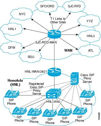
Table 1-9 lists the hardware and software components used in the Non-Cisco Unified CallManager Interoperability Site model.
Centralized TFTP Cluster Site
The Centralized TFTP Cluster Site model consists of a site called San Jose (SJC). This site was used to test centralized TFTP servers.
Table 1-10 lists the hardware and software components used in the Centralized TFRP Cluster Site model.
Europe and Emerging Markets Site Models
Six site models were created and tested for Cisco Unified Communications Release 5.0 testing for Europe and Emerging Markets (EUEM) IP telephony. Each site model tested specific hardware and software components, features, functions, protocols, and related items.
A site model includes a site with a three-letter name (for example, CDG, GVA, and MAD). Examples throughout this manual refer to these site names.
The following sections describe each site model in detail. Each section includes an explanation of the design characteristics of the site model, and includes a table that lists the hardware and software components used in the model. The tables contain the following information for each component:
•
•
•
Table 1-11 lists the site models and references to sections that provide detailed information.
Table 1-11 EUEM Site Models
Paris (CDG)
Geneva (GVA)
Madrid (MAD)
Cisco Unified CallManager Interoperability Site (Europe and Emerging Markets)
London (LGW)
Reykjavik (RKV)
Warsaw (WAW)
For an illustration showing how these site models were deployed for testing, see Figure 1-2.
Large Multi-Site Centralized with Unified SRST
The Large Multi-Site Centralized with Unified SRST site model consists of one site called Paris (CDG). This site model represents an international deployment with up to 100 remote sites deployed across various countries. In includes Cisco Unity, Cisco Unified MeetingPlace Express, and third-party components. Cisco Unified CallManager uses QSIG, H.323, and SIP to interoperate between sites. Remote sites are interconnected through the WAN and all are RSVP-enabled to the central site.
In this model, a Cisco Unified CallManager cluster serves 6000 phone in local and remote locations, with all endpoints and gateways fully encrypted (RTP and signalling). PBXs that support the QSIG ISO variant connect to this cluster through direct QSIG links. The Cluster connects to the rest of the network through legacy ATM/frame relay and MPLS WAN networks.
Calls between the CDG site, the LGW site, and the MAD site are provided by Annex M1 intercluster trunks. Cisco Unity (with failover capabilities) provides voice messaging. Lotus Domino is used for unified messaging. PBX users access voice messaging features through the QSIG trunks to Cisco Unified CallManager.
Access to the PSTN for normal off-net calls is provided by ten E1 ETSI PRI links to the PSTN. Remote sites have either centralized breakout to the PSTN or local PSTN breakout using E1 PRI, BRI, or FXO connections. PSTN access is controlled by Cisco Unified CallManager using MGCP, H.323, or SIP. Unified SRST is used in each remote site.
This site model includes two Cisco Unified MeetingPlace Express servers. One is connects to Cisco Unified CallManager through a direct H.323 link. The other connect to Cisco Unified CallManager through an H.323 gatekeeper. Both Cisco Unified MeetingPlace Express servers can receive and make calls from local and remote sites.
Access to the SIP network is provided through a SIP trunk to a remote Cisco SIP Proxy Server (CSPS). Access to third-party services such as operator console, billing, and voice recording, if available, is provided locally. Some of sites will also have video endpoints and Cisco Unified Videoconferencing Gateways, and remote QSIG PBXs.
The Large Multi-site Centralized with Unified SRST site model has these design characteristics:
•
•
•
•
•
•
•
•
•
•
•
•
•
•
Table 1-12 lists the hardware and software components used in the Multi-site Centralized, Clustering over the WAN with Unified SRST site model.
Medium Site
The Medium Site model consists of one site called Geneva (GVA). In this model, a Cisco Unified CallManager cluster serves 2000 phones. The Cisco Unified CallManager cluster connects to the rest of the network through legacy ATM / Frame Relay and MPLS WAN networks.
A local Cisco Unity Connection provides voice messaging services for local PBX and Cisco Unified CallManager users. Access to the PSTN for normal off-net calls is provided by five E1 RTSI PRI links to the PSTN. Access to other sites and to services such as Cisco Unified MeetingPlace Express is provided by H.323 gatekeeper controlled trunks and an IP-to-IP gateway. Access to the SIP network is through a SIP trunk to a remotely located CSPS. Third-party operator consoles are provided on Cisco Unified CallManager to serve local phones and to provide backup to the operator console in the CDG site.
The Medium Site model has these design characteristics:
•
•
•
•
•
•
•
•
Table 1-13 lists the hardware and software components used in the Medium Site model.
Small Site (EUEM)
The Small Site model for Europe and Emerging Markets consists of one site called Madrid (MAD). In this model, a Cisco Unified CallManager cluster serves 750 phones in a single campus. A PBX that supports the ISO QSIG variant connects to this cluster through direct QSIG links.
Cisco Unity Connection connects to the cluster through the QSIG-enabled intercloster trunk via the LGW site and provide voice messaging functions to PBX users and to Cisco Unified CallManager users. PBX users have access to Cisco Unified CallManager through a QSIG trunk.
The Cluster connects to the rest of the network through legacy ATM/frame relay and MPLS WAN networks. Calls between this site and other sites in the network are made through the WAN with two Annex M1 intercluster trunks to the CDG and LGW sites.
Access to the PSTN as a backup route to other sites and for normal off-net calls is provided by two E1 ETSI PRI links to the PSTN. Access to services such as Cisco Unified MeetingPlace Express, and operator consoles also is provided through the Annex M1 intercluster trunk to the Large Multi-Site Centralized with Unified SRST site.
The Small Site model has these design characteristics:
•
•
•
•
•
•
•
•
•
Table 1-14 lists the hardware and software components used in the Small Site model.
Cisco Unified CallManager Interoperability Site (Europe and Emerging Markets)
The Cisco Unified CallManager Interoperability Site model for EUEM consists of one site called London (LGW). In this model, a Cisco Unified CallManager cluster serves 2,000 phones in a single campus. A PBX that supports the ISO QSIG variant connects to this cluster through direct QSIG links.
The Cluster connects to the rest of the network through legacy ATM/frame relay and MPLS WAN networks. Calls between this site and other sites in the network are made through the WAN with two Annex M1 intercluster trunks to the CDG and MAD sites.
Some PBX and Cisco Unified CallManager users have voice messaging services provided by Cisco Unity Connection, which is connected to the cluster through an SCCP link. The PBX user access voice messages through QSIG trunks to Cisco Unified CallManager.
Other PBX and CCM users have access to Unified messaging with Unity and Domino located in the CDG Site via the Annex M1 Inter Cluster Trunk. MWI events and message store and retrieval for both the connected PBX and the CCM users is all passed Annex M1 between the sites.
Access to the PSTN as a backup route to other sites and for normal off-net calls is provided by 5 E1 ETSI PRI links to the PSTN. Access to Cisco Unified MeetingPlace Express, the Cisco Unified CallManager network, and any non-directly connected clusters is provide through remotely located H.323 gatekeepers. Access to the SIP network is provided through a SIP trunk to a remotely located CSPS. Operator console services are provided in the CDG site through the Annex M1 intercluster trunk.
The Cisco Unified CallManager Interoperability Site model has these design characteristics:
•
•
•
•
•
•
•
•
•
•
Table 1-15 lists the hardware and software components used in the Cisco Unified CallManager Interoperability Site model.
Non-Cisco Unified CallManager Interoperability Site (EUEM)
The Non-Cisco Unified CallManager Interoperability Site model for EUEM consists of one site called Reykjavik (RKV). This site model is designed to test interoperability of all components in the other models with CSPS controlled endpoints.
The Non-Cisco Unified CallManager Interoperability Site model includes a Cisco SIP Proxy Server (CSPS), and SIP phones and PSTN gateways connected to the CSPS. Each Cisco Unified CallManager cluster also has connectivity to the CSPS for interoperability.
Table 1-16 lists the hardware and software components used in the Non-Cisco Unified CallManager Interoperability Site model.
Small Campus Multi-Site H.323
The Small Campus Multi-Site H.323 site model consists of one site called Warsaw (WAW). This model includes 13 Cisco Unified CallManager Express sites connected to each other and to the rest of the network through H.323 gatekeepers. Each Cisco Unified CallManager cluster uses an IP-to-IP gateway and MTP to communicate with the Cisco Unified CallManager Express systems in this site, and with the Cisco Unified MeetingPlace Express system located in the CDG site.
Each Cisco Unified CallManager Express system has either Cisco Unity Express installed locally installed, or will access Cisco Unity Connection through an MWI relay gateway that is located in the GVA site.
The Small Campus Multi-Site H.323 model has these design characteristics:
•
•
•
•
Table 1-17 lists the hardware and software components used in the Small Campus Multi-Site H.323 model.
 Feedback