Rear Panel Layout
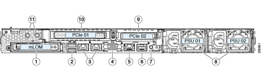
This section details the rear panel layout, LEDs and ports.
|
1 |
Modular LAN on Motherboard (mLOM) card slot (not populated) |
||||
|
2 |
USB 3.0 ports (two slots) |
||||
|
3 |
Ethernet Ports (LAN3 and LAN4) |
||||
|
As depicted in figure, |
|||||
|
Label |
Port |
Port Status |
|||
|
3a |
LAN3 |
Active - Use this port |
|||
|
3b |
LAN4 |
Inactive |
|||
|
3a |
LAN3 → Expressway Dedicated Management Interface (DMI) port on LAN3. It is located on the back of the server.
|
||||
|
4 |
VGA video connector |
||||
|
5 |
Cisco Integrated Management Controller (CIMC) Port (1 Gb Ethernet) |
||||
|
6 |
Serial port (RJ-45 connector) |
||||
|
7 |
Rear identification button/LED |
||||
|
8 |
Power supplies PSU 01 and PSU 02. The second power supply can be added for 1+1 redundancy. |
||||
|
9 |
Slot 2: Low-profile PCIe slot on riser (not populated) |
||||
|
10 |
Slot 1: Standard-profile PCIe slot on riser; houses two SFP ports Left port is LAN1 (NIC1) in the Expressway user interface. Right port is LAN2 (NIC2) if used in the interface. |
||||
For more information on the method to configure a Dedicated Management Interface (DMI), see Cisco Expressway Administrator Guide.
 Feedback