Packaged CCE 2000 Agents Deployment
Follow this sequence to configure components for Packaged CCE 2000 Agents deployment.
|
Sequence |
Task |
|---|---|
|
1 |
|
|
2 |
|
|
3 |
If Media Server is external, Configure Media Server |
|
4 |
|
|
5 |
|
|
6 |
|
|
7 |
|
|
8 |
Configure Cisco Unified Customer Voice Portal Reporting Server (optional) |
|
9 |
Configure VVB (optional) |
|
10 |
|
|
11 |
|
|
12 |
Configure Enterprise Chat and Email (ECE) (optional) |
Configure CCE Component
Follow this sequence to configure the core CCE components.
|
Sequence |
Task |
|---|---|
|
1 |
|
|
2 |
|
|
3 |
|
|
4 |
|
|
5 |
Cisco SNMP Setup (optional) |
|
6 |
For details on CA certificate, see Generate and Import CA Signed Certificate in AW Machine |
|
7 |
For details on self-signed certificate, see Generate and Import Self-signed Certificate in AW Machine |
Configure SQL Server for CCE Components
The following procedure must be done in Logger, Rogger, and AW Machines.
Procedure
|
Step 1 |
Open Microsoft SQL Server Management Studio. |
|
Step 2 |
Log in. |
|
Step 3 |
Expand Security and then Logins. |
|
Step 4 |
If the BUILTIN\Administrators group is not listed:
|
Set up Organizational Units
Add a Domain
Procedure
|
Step 1 |
Log in with a Domain Administrator privilege. |
|
Step 2 |
Open the Domain Manager Tool from Unified CCE Tools shortcut on your desktop. |
|
Step 3 |
Click Select. under Domains. |
|
Step 4 |
You can add domains through the Select Domains dialog box, or you can add a domain manually if the target domain cannot be detected automatically. To add domains by using the controls in the Select Domains dialog box:
To add a domain manually:
|
Add Organizational Units
Use the Domain Manager tool to create the Cisco root Organizational Unit (OU) for a domain, and then create the facility and instance OUs.
The system software always uses the root OU named Cisco_ICM. You can place the Cisco_ICM OU at any level within the domain where the Unified ICM Central Controller is installed. The system software components locate the root OU by searching for this name.
The user who creates the Cisco Root OU automatically becomes a member of the Setup Security Group for the Cisco Root OU. In effect, this user is granted privileges to all Unified CCE tasks in the domain.
Procedure
|
Step 1 |
Log in with a domain administrator privilege and open the Domain Manager Tool from Unified CCE Tools shortcut on the desktop. |
|
Step 2 |
Choose the domain. |
|
Step 3 |
If this OU is the first instance, then perform the following steps to add the Cisco_ICM root: |
|
Step 4 |
Add the facility OU:
|
|
Step 5 |
Add the instance OU:
|
|
Step 6 |
Click Close. |
Add Users to Security Groups
To add a domain user to a security group, use this procedure. The user is then granted the user privileges to the functions that are controlled by that security group.
Procedure
|
Step 1 |
Open the Domain Manager tool and select the Security Group (Config or Setup) you want to add a user to. |
|
Step 2 |
Under Security group, click Members. |
|
Step 3 |
Under Users, click Add. |
|
Step 4 |
Select the domain of the user you want to add. |
|
Step 5 |
(Optional) In the Optional Filter field, choose to further filter by the Name or User Logon Name, apply the search condition, and enter the search value. |
|
Step 6 |
Click Search. |
|
Step 7 |
Select the member you want to add to the Security Group from the search results. |
|
Step 8 |
Click OK. |
Add Users to Local Administrators Group
 Note |
You can add a domain group to local Administrators group of the server to provide users in domain group administrative permission on the server, provided the users are immediate members of the domain group. |
Procedure
|
Step 1 |
Click > Computer Management. |
|
Step 2 |
Select Local Users and Groups. |
|
Step 3 |
Double-click Groups. |
|
Step 4 |
Right-click Administrators. Select Properties. |
|
Step 5 |
Click Add and enter the user name or domain group name in the Edit the Object names to select check box. |
|
Step 6 |
Select Check Names to validate the names. |
|
Step 7 |
After the name is successfully validated, click OK. |
|
Step 8 |
Click Apply and OK in the Properties dialog box. |
|
Step 9 |
Close the Computer Management and Server Manager windows. |
Initialize the Packaged CCE 2000 Agents Deployment Type
Initialize the Packaged CCE deployment using Unified CCE Administration.
When you sign into Unified CCE Administration for the first time, you are prompted to enter information and credentials for the components in your deployment. Packaged CCE uses this information to configure the components and build the System Inventory.
If you are in the process of upgrading from an earlier release, Packaged CCE prompts you only for missing information and credentials; you may not need to perform each step.
Note |
After a Packaged CCE deployment is initialized, you cannot switch to another deployment type. |
Note |
The system does not support IP address change. This is applicable for all the Hostname/ IP Address fields. |
Procedure
|
Step 1 |
Sign into Unified CCE Administration using the Active Directory username (user@domain) and password (https://<IP Address>/cceadmin, where <IP Address> is the address of the Side A Unified CCE AW-HDS-DDS). |
||||||||||||||||||||
|
Step 2 |
On the Deployment Type page, select a Deployment Type and an Instance from the respective drop-down lists. You must be a member of the Setup security group for the instance you select. Click Next. |
||||||||||||||||||||
|
Step 3 |
On the VM Host page, enter the IP address, Username, and Password for the VMware hosts for Side A and Side B. The VMware hosts are the two servers on which ESXi is installed. The username and password fields are the host login names and passwords configured in ESXi.
Users must have Read and Reboot permissions on the hosts. To enable these permissions in the VMware Host Client, set the following in Manage Permissions:
|
||||||||||||||||||||
|
Step 4 |
Select the hardware layout type as M3/M4 Tested Reference Configuration or M5 Tested Reference Configuration / Specification Based Configuration and click Next. Packaged CCE validates the hosts in your deployment.
|
||||||||||||||||||||
|
Step 5 |
On the Credentials page, enter the specified information for each component in your deployment. After entering information for a component, click Next. The system validates the credentials you entered before prompting you for the next component's information.
|
||||||||||||||||||||
|
Step 6 |
On the Settings page, select the following:
Click Next. See Automated Initialization Tasks for Components for more information. |
||||||||||||||||||||
|
Step 7 |
After the automated initialization tasks complete, click Done. If one of the automated initialization tasks fails, correct the errors and then click Retry. If the retry is successful, the automated initialization continues. For some task failures, all completed tasks must be reverted before the task can be retried. You see a message informing you that the system needs to be reverted to a clean state. Click OK, and then after the system is in a clean state, click Start Over. |
Note |
The System Inventory displays alerts for some machines when it opens after initialization completes and you click Done. These alerts will be cleared after you configure Unified Communications Manager. |
What to do next
After you have configured the deployment, you can specify system-level settings. For example, you can enter labels for Unified Communications Manager, Unified CVP, and outbound calls. See Miscellaneous.
Automated Initialization Tasks for Components
Packaged CCE performs the following tasks during initialization.
| Component | Automated Initialization Tasks |
|---|---|
|
Unified CCE Rogger |
|
|
Unified CCE PG |
|
|
Unified CCE AW-HDS-DDS |
|
|
Unified Communications Manager |
|
|
Unified Customer Voice Portal |
|
|
Unified CVP Reporting Server |
|
|
Unified Intelligence Center |
|
|
Cisco Finesse |
|
System Inventory for Packaged CCE 2000 Agents Deployment
Note |
The System Inventory shows IPv4 addresses only. |
The System Inventory is a visual display of the machines in your deployment, including: Virtual Machine Hosts (ESXi servers), Virtual Machines (VMs) on Side A, VMs on Side B, External Machines, Gateways, and Cisco Virtualized Voice Browsers (VVB). You can access the System Inventory after you have completed the change to a Packaged CCE deployment.
Access the System Inventory by navigating to .
System Inventory contents are updated when you select or change the deployment type and after regular system scans. If a system scan detects VMs that do not conform to Packaged CCE requirements, the Configure your deployment pop-up window opens automatically, detailing the errors. You can access the System Inventory again after you have corrected the errors and completed the Configure your deployment pop-up window.
For more details about the Packaged CCE requirements, see Server Status pop-up window, see Monitor Server Status Rules for Packaged CCE 2000 Agents Deployment.
| Item | Notes | Actions | ||||||
|---|---|---|---|---|---|---|---|---|
| Validate |
If a system scan detects an error or warning for validation rules, correct the error, and then click Validate to run an immediate scan and verify that you corrected the problem. |
Click Validate. | ||||||
| Side A | This panel shows all VMs on Side A. |
The System Inventory displays read-only information for the following VMs:
The following VMs are editable. Click the VM pencil icon to edit the following fields:
You can launch the administration tool for these VMs by clicking the VM arrow icon:
You can perform the full synchronization or differential synchronization of the configurations of various components. For more information on the machines that support data synchronization, see Device Out of Sync Alerts.
For more information, see Unified CVP Statistics and Unified CVP Reporting Statistics. |
||||||
| Side B | This panel shows all VMs on Side B. |
The System Inventory displays read-only information for the following VMs:
The following VMs are editable. Click the VM pencil icon to edit the following fields:
If the CVP Reporting server VM is re-imaged or re-installed, you need to initialize the CVP Reporting server. To initialize the CVP Reporting Server , click the Initialize icon and then click Yes to confirm.
You can perform the full synchronization or differential synchronization of the configurations of various components. For more information on the machines that support data synchronization, see Device Out of Sync Alerts.
For more information, see Unified CVP Statistics and Unified CVP Reporting Statistics. |
||||||
|
External Machines |
This section shows all external machines in the deployment, and can include any of the following:
|
To add or update the external machines, see Add External Machines. You can perform the full synchronization or differential synchronization of the configurations of various components. For more information on the machines that support data synchronization, see Device Out of Sync Alerts.
To associate the external HDS with a default Cisco Identity Service (IdS) for single sign-on:
To delete, click the x on the machine. Confirm the deletion. You can open the administration tool for these external machines by clicking the arrow icon in the machine box:
|
Monitor Server Status Rules for Packaged CCE 2000 Agents Deployment
In Packaged CCE 2000 Agents deployment, the Inventory displays the total number of alerts for machines with validation rules. Click the alert count to open the Server Status popup window, which lists all of the rules for that machine and indicates which have warnings and errors. Rules are grouped by these categories:
| Server Status Category | Description | Example Rules | ||
|---|---|---|---|---|
|
Configuration |
Rules for installation and configuration of a component. These rules identify problems with mismatched configuration between components, missing services, and incorrectly configured services. |
Unified CCE Rogger: The trace level must be set to normal to ensure performance. Unified CVP: The names of the SIP Server Groups on CVP containing Communications Manager addresses must match the Communications Manager Cluster Fully Qualified Domain Name. |
||
|
Operations |
Rules for the runtime status of a component. These rules identify services and processes that cannot be reached, are not running, or are not in the expected state. |
Unified CCE Rogger: The central controller agent process (ccagent.exe) must be in service for both PGs.
|
||
|
System Health |
Metrics to monitor the CPU, memory, and disk usage of a component's Virtual Machine (VM) as reported by ESXi over the last 10 minutes. The memory and CPU usage may differ slightly from system tools reported by the VM itself. For VM Hosts, these metrics also include datastore performance information. For VM Hosts under M5 Tested Reference Configuration / Specification Based Configuration, these metrics include CPU reservation, CPU oversubscription, memory reservation and datastore utilization information. |
All: Memory usage as reported by ESXi - 17% For VM Hosts under M5 Tested Reference Configuration / Specification Based Configuration:
|
||
|
VM |
VM requirements for a component. |
All: VMware Tools must be up to date |
||
|
System Validation |
Rules for Unified CCE database and configuration settings. These rules identify whether the configuration of objects in your deployment match the requirements and limits for Packaged Contact Center Enterprise.
|
Side A Unified CCE AW-HDS-DDS: Agent Desk Settings: Ring No Answer Times must not be set. Side A Unified CCE AW-HDS-DDS: Application Gateway Side A Unified CCE AW-HDS-DDS: Application Instance: Up to 12 Application Instances can be defined. |
VM Validation
The validation for the Packaged CCE: 2000 Agents deployment type makes the following checks to ensure hardware compliance and conformance with the Cisco-provided OVA files.
-
For Hosts:
-
BIOS
-
Minimum number of CPU cores
-
Minimum memory
-
Data store size
-
-
For VMs:
-
Number of virtual CPU cores
-
Number of configured networks
-
Virtual network card driver (except for Unified CM)
-
VM is powered on
-
CPU reservation
-
Exact memory
-
Exact disk size
-
Exact number of disks
-
VMware tools
-
Configure Cisco Unified Contact Center Enterprise PG
The following table outlines the configuration task for Media Routing Peripheral Gateway for the Packaged CCE 2000 Agents deployment.
|
Configuration Task |
|---|
Cisco SNMP Setup
Complete the following procedures to configure Cisco SNMP:
Add Cisco SNMP Agent Management Snap-In
You can configure Cisco SNMP Agent Management settings using a Windows Management Console snap-in.
Complete the following procedure to add the snap-in and change Cisco SNMP Management settings.
Procedure
|
Step 1 |
From the Start menu, enter mmc.exe /32. |
|
Step 2 |
From the Console, choose. |
|
Step 3 |
In the Add or Remove Snap-ins dialog box, choose Cisco SNMP Agent Management from the list of available snap-ins. Click Add. |
|
Step 4 |
In the Selected snap-ins pane, double-click Cisco SNMP Agent Management. |
|
Step 5 |
In the Extentions for Cisco SNMP Agent Management dialog box, select Always enable all available extentions. Click OK. |
|
Step 6 |
In the Add/Remove Snap-in window, click OK. The Cisco SNMP Agent Management Snap-in is now loaded into the console. |
Save Cisco SNMP Agent Management Snap-In View
After you load the Cisco SNMP Agent Management MMC snap-in, you can save the console view to a file with a .MSC file extension. You can launch the file directly from Administrative Tools.
Complete the following procedure to save the Cisco SNMP Agent Management snap-in view.
Procedure
|
Step 1 |
Choose . |
|
Step 2 |
In the Filename field, enter Cisco SNMP Agent Management. |
|
Step 3 |
In the Save As type field, choose a file name to map to the administrative tools such as Microsoft Management Console Files(*.msc). |
|
Step 4 |
Click Save. |
Set Up Community Names for SNMP V1 and V2c
If you use SNMP v1 or v2c you must configure a community name so that Network Management Systems (NMSs) can access the data your server provides. Use SNMP community names to authenticate data exchange of SNMP information. An NMS can exchange SNMP information only with servers that use the same community name.
Complete the following procedure to configure the community name for SNMP v1 and v2c.
Before you begin
Ensure Cisco SNMP is added and saved using the procedures Add Cisco SNMP Agent Management Snap-In and Save Cisco SNMP Agent Management Snap-In View.
Procedure
|
Step 1 |
Choose . |
|
Step 2 |
Right-click Cisco SNMP Agent Management and choose Run as administrator. |
|
Step 3 |
The Cisco SNMP Agent Management screen lists some of the configurations that require SNMP for traps and system logs. |
|
Step 4 |
Right-click Community Names (SNMP v1/v2c) and choose Properties. |
|
Step 5 |
In the Community Names (SNMP v1/v2c) Properties dialog box, click Add New Community. |
|
Step 6 |
In the Community Name field, enter a community name. |
|
Step 7 |
In the Host Address List, enter the host IP address. |
|
Step 8 |
Click Apply and click OK. |
Set Up SNMP User Names for SNMP V3
If you use SNMP v3 you must configure a user name so that NMSs can access the data your server provides.
Complete the following procedure to configure a user name for SNMP v3.
Before you begin
Ensure Cisco SNMP is added and saved using the procedures Add Cisco SNMP Agent Management Snap-In and Save Cisco SNMP Agent Management Snap-In View.
Procedure
|
Step 1 |
From the Console Root, choose . |
|
Step 2 |
Click Add New User. |
|
Step 3 |
In the User Name field, enter a username. |
|
Step 4 |
Click Save. |
|
Step 5 |
The username appears in the Configured Users pane at the top of the dialog box. |
|
Step 6 |
Click Apply and click OK. |
Set Up SNMP Trap Destinations
You can configure SNMP Trap Destinations for SNMP v1, SNMP v2c, and SNMP v3. A Trap is a notification that the SNMP agent uses to inform the NMS of a certain event.
Complete the following procedure to configure the trap destinations.
Before you begin
Ensure Cisco SNMP is added and saved using the procedures Add Cisco SNMP Agent Management Snap-In and Save Cisco SNMP Agent Management Snap-In View.
Procedure
|
Step 1 |
From the Console Root, choose . |
|
Step 2 |
Click Add Trap Entity. |
|
Step 3 |
Click the SNMP version that your NMS uses. |
|
Step 4 |
In the Trap Entity Name field, enter a name for the trap entity. |
|
Step 5 |
Choose the User Name/Community Name that you want to associate with this trap. This list is auto-populated with existing configured users/community names. |
|
Step 6 |
Enter one or more IP addresses in the IP Address entry field. Click Insert to define the destinations for the traps. |
|
Step 7 |
Click Apply and click Save to save the new trap destination. The trap entity name appears in the Trap Entities section at the top of the dialog box. |
|
Step 8 |
Click OK. |
Set Up SNMP Syslog Destinations
You can configure Syslog destinations for SNMP from the Cisco SNMP Agent Management Snap-in.
Complete the following procedure to configure Syslog destinations.
Procedure
|
Step 1 |
From the Console Root, choose . |
|
Step 2 |
Choose an Instance from the list box. |
|
Step 3 |
Check Enable Feed. |
|
Step 4 |
Enter an IP address or host name in the Collector Address field. |
|
Step 5 |
Click Save. |
|
Step 6 |
Click OK and restart the logger. |
Configure Cisco Unified Customer Voice Portal
Note |
The CVP configurations are site specific. Side A and Side B configurations per site must be the same. |
|
Configuration Tasks |
|---|
|
To secure communication between Call Server and ICM, see Secure GED 125 Communication between Call Server and ICM. For more information about securing CVP communication, see Unified CVP Security |
| For web secure communication, see pcce_b_admin-and-config-guide_120_appendix_01000001.html#task_4D95BC1D59CD9491C6EA4C3796DB262A |
|
To change the default settings, see CVP Server Services Setup |
Configure Cisco Unified Communications Manager
The following table outlines the Cisco Unified Communications Manager configuration tasks for Packaged CCE 2000 Agents deployment.
|
Configuration Tasks |
|---|
| For details on CA and self-signed certificate, see Secure Communication on CUCM |
|
Configure Ingress Gateways for Locations-based Call Admission Control |
Configure Fully Qualified Domain Name
Procedure
|
Step 1 |
Open Cisco Unified Communications Manager and log in. |
||
|
Step 2 |
Navigate to . |
||
|
Step 3 |
Fill in with the Fully Qualified Domain Name of your cluster. Example:
|
||
|
Step 4 |
Click Save. |
Configure Cisco Unified Communications Manager Groups
Procedure
|
Step 1 |
Select Cisco Unified CM Administrator from the Navigation menu and click Go. |
|
Step 2 |
Select System > Cisco Unified CM Group. |
|
Step 3 |
Click Find. Then click Default. |
|
Step 4 |
Move the two subscribers from the Available panel to the Selected panel. |
|
Step 5 |
Click Save. |
|
Step 6 |
Click Reset. |
|
Step 7 |
On the Device Reset popup, click Reset. |
|
Step 8 |
Click Close. |
Configure Conference Bridges
Procedure
|
Step 1 |
Select . |
|
Step 2 |
Click Add New. |
|
Step 3 |
Select Conference Bridge Type of Cisco IOS Conference Bridge. |
|
Step 4 |
In the Conference Bridge name field, enter a unique identifier for the conference bridge name that matches the configuration on the gateway. |
|
Step 5 |
Select a Device Pool. |
|
Step 6 |
Click Save. |
|
Step 7 |
Click Apply Config. |
Configure Media Termination Points
Procedure
|
Step 1 |
Select . |
|
Step 2 |
Click Add New. |
|
Step 3 |
In the Media Termination Point Name field, enter a unique identifier for the media termination that coincides with the configuration on the gateway. |
|
Step 4 |
Select a Device Pool. |
|
Step 5 |
Click Save. |
|
Step 6 |
Click Apply Config. |
Transcoder Configuration in Unified CM and IOS Gateway
A transcoder is required for multicodec scenarios to convert a stream from a G.711 codec to a G.729 codec.
For more information about transcoder configuration in Unified Communications Manager and gateway, see the section "Configure Transcoders and Media Termination Points" in the System Configuration Guide for Cisco Unified Communications Manager at https://www.cisco.com/c/en/us/support/unified-communications/unified-communications-manager-callmanager/products-installation-and-configuration-guides-list.html.
Configure Transcoders
Procedure
|
Step 1 |
In Unified Communications Manager Administration, select Media Resources > Transcoder. |
|
Step 2 |
Click Add New. |
|
Step 3 |
For Transcoder Type, select Cisco IOS enhanced media termination point. |
|
Step 4 |
In the Device Name field, enter a unique identifier for the transcoder name that coincides with the configuration on the gateway. In the following example, this is gw70xcode. |
|
Step 5 |
In the Device Pool field, select the appropriate device pool. |
|
Step 6 |
Click Save. |
|
Step 7 |
Click Apply Config. |
Configure the CVP Call Server Dial Peers in Ingress Gateway
The Ingress Gateway to Unified CVP outbound dial peer configuration uses the IPv4 address of Unified CVP as the session target.
Configure Media Resource Groups
Procedure
|
Step 1 |
Select . |
|
Step 2 |
Add a Media Resource Group for Conference Bridges.
|
|
Step 3 |
Add a Media Resource Group for Media Termination Point.
|
|
Step 4 |
Add a Media Resource Group for Transcoder.
|
|
Step 5 |
Click Save. |
Configure and Associate Media Resource Group List
Procedure
|
Step 1 |
Select . |
|
Step 2 |
Click Add New and enter a Name. |
|
Step 3 |
Add a Media Resource Group list and associate all of the media resource groups. Click Save. |
|
Step 4 |
Select . Click Find. Select the appropriate device pool. |
|
Step 5 |
From the Media Resource Group List drop-down list, choose the media resource group list added in Step 2. |
|
Step 6 |
Click Save. Click Reset. |
Configure CTI Route Point
Procedure
|
Step 1 |
In Cisco Unified CM Administration, select . |
||
|
Step 2 |
Click Add New. |
||
|
Step 3 |
Set a device name; for example, PCCEInternalDNs. |
||
|
Step 4 |
For Device Pool, select Default. |
||
|
Step 5 |
Select a Media Resource Group List from the list. |
||
|
Step 6 |
Click Save. |
||
|
Step 7 |
Click on Line [1] to configure the directory number associated with this route point. This directory number will be a pattern that is intended to match any of the internal Dialed Numbers you configure in Packaged CCE for internally routed calls. (For instance, for Transfers and Conferences).
|
||
|
Step 8 |
Select . |
||
|
Step 9 |
Select pguser created during Packaged CCE automated initialization. |
||
|
Step 10 |
Select the CTI Route Point from the list of Available Devices, and add it to the list of Controlled Devices. |
||
|
Step 11 |
Click Save. |
Configure Ingress Gateways for Locations-based Call Admission Control
Locations-based call admission control (CAC) is used in the Unified CCE branch-office call flow model (also known as the Centralized Model). This means that all servers (Unified CVP, Unified CCE, Unified Communications Manager, and SIP Proxy server) are centralized in one or two data centers, and each branch office.
Configure Unified Communications Manager to use the Ingress gateway instead of Unified CVP as the originating location of the call. This configuration ensures that CAC can be properly adjusted based on the locations of the calling endpoint and the phone.
Important |
Do not define Unified CVP as a gateway device in Unified Communications Manager. |
Procedure
|
In Cisco Unified CM Administration, define the Ingress gateways as gateway devices. Assign the correct location to the devices. |
Add a SIP Profile in Unified CM
This option allows a dual-stack SIP trunk to offer both IPv4 and IPv6 media. Perform this procedure for IPv6-enabled deployments only.
Procedure
|
Step 1 |
From Cisco Unified CM Administration, choose . |
|
Step 2 |
Click Add New and enter the name of the SIP profile. |
|
Step 3 |
Check the Enable ANAT check box on the SIP Profile. |
|
Step 4 |
Save your changes. |
Configure Trunk
There are two Unified CVP Servers and each must be associated with a SIP trunk in Unified Communications Manager. The following procedure explains how to configure the SIP trunks, each targeting a different Unified CVP Server.
Actual site topology may necessitate the use of alternate SIP trunk plans, which are supported as long as both Unified CVP Servers are targeted by the configured SIP trunks.
Procedure
|
Step 1 |
In Unified Cisco CM Administration, select Device > Trunk. |
|
Step 2 |
Click Add New. |
|
Step 3 |
From the Trunk Type drop-down list, choose SIP Trunk, and then click Next. |
|
Step 4 |
Enter the following in the Device Information section:
|
|
Step 5 |
Scroll down to the SIP Information section: |
|
Step 6 |
Click Save. |
|
Step 7 |
Click Reset. |
|
Step 8 |
Repeat for all the remaining Unified CVP servers in the deployment. |
Configure Route Group
Complete the following procedure to create a route group.
Procedure
|
Step 1 |
In Unified Communications Manager, select . |
|
Step 2 |
Click Add New. |
|
Step 3 |
Enter a name for the route group; for example, CVP Route Group. |
|
Step 4 |
Using the Add to Route Group button, add all CVP Trunks as Selected Devices. |
|
Step 5 |
Click Save. |
Configure Route List
Complete the following procedure to add a route list to the route group.
Procedure
|
Step 1 |
In Unified Communications Manager, select . |
|
Step 2 |
Click Add New. |
|
Step 3 |
Enter a name for the route list; for example, CVP Route List. |
|
Step 4 |
Select a Cisco Unified Communications Manager Group. |
|
Step 5 |
Add the route group you created. |
|
Step 6 |
Click Save. |
Configure Route Pattern
Complete the following procedure to add a route pattern to the route list.
Procedure
|
Step 1 |
In Unified Communications Manager, select . |
|
Step 2 |
Click Add New. |
|
Step 3 |
Enter a route pattern of 8881111000XXXX. |
|
Step 4 |
Select the route list that you created. |
|
Step 5 |
Keep all defaults in all panels |
|
Step 6 |
Click Save. |
|
Step 7 |
Click OK at the message about the Forced Authorization Code. You do not want a Forced Authorization Code. |
Configure Cisco Unified Intelligence Center
Follow this sequence to configure the Cisco Unified Intelligence Center for Packaged CCE 2000 Agentsdeployment
|
Sequence |
Task |
|---|---|
|
1 |
For details on security certificate, see Cisco Unified Intelligence Center User Guide at https://www.cisco.com/c/en/us/support/customer-collaboration/unified-intelligence-center/products-user-guide-list.html |
|
2 |
For details on self-signed certificate, see Add IdS Certificate to AW Machine |
|
3 |
|
|
4 |
|
|
5 |
Configure Unified Intelligence Center Data Sources for External HDS
Perform this procedure only if your deployment includes an external HDS and you wish to have a longer retention period.
Before you begin
Configure the Unified Intelligence Center SQL user for the External HDS databases before configuring the data sources (applicable for 4000 Agents and 12000 Agents). For more information, refer the Configure Unified Intelligence Center SQL User Account on the External HDS section in the Cisco Packaged Contact Center Enterprise Installation and Upgrade Guide at https://www.cisco.com/c/en/us/support/customer-collaboration/packaged-contact-center-enterprise/products-installation-guides-list.html
Procedure
|
Step 1 |
Sign in to Unified Intelligence Center with your Cisco Intelligence Center administrator account (https://<hostname/ IP address of CUIC Publisher>:8444/cuicui). |
|
Step 2 |
Select . |
|
Step 3 |
Click Data Sources in the left panel. |
|
Step 4 |
Select the UCCE Historical data source. Click Edit.
|
|
Step 5 |
Click the Secondary tab to configure Unified CCE Historical Data Source.
|
|
Step 6 |
Repeat this procedure for the UCCE Realtime datasource for 4000 or 12000 Agents deployment. The Database Name for the Realtime Data Source is {instance}_awdb. |
Download Report Bundles
The following Cisco Unified Intelligence Center report bundles are available as downloads from Cisco.com https://software.cisco.com/download/type.html?mdfid=282163829&catid=null. Click the Intelligence Center Reports link to view all available report bundles:
-
Realtime and Historical Transitional templates - Introductory templates designed for new users. These templates are simplified versions of the All Fields templates, and are similar to templates available in other contact center solutions.
-
Realtime and Historical All Fields templates - Templates that provide data from all fields in a database. These templates are most useful as a basis for creating custom report templates.
-
Live Data templates - Templates that provide up to the moment data for contact center activity.
-
Realtime and Historical Outbound templates - Templates for reporting on Outbound Option activity. Import these templates if your deployment includes Outbound Option.
-
Realtime and Historical SocialMiner templates - Templates for reporting on SocialMiner activity. Import these templates if your deployment includes SocialMiner.
-
Cisco Unified Intelligence Center Admin Security templates - Templates to report on Cisco Unified Intelligence Server audit trails, permissions, and template ownership.
Some of the templates in these bundles are not applicable in Cisco Packaged CCE deployment. See the Cisco Packaged Contact Center Enterprise Reporting User Guide at https://www.cisco.com/en/US/products/ps12586/tsd_products_support_series_home.html for more information about the templates used in Packaged CCE deployments.
Additionally, sample custom report templates are available from Cisco DevNet (https://developer.cisco.com/site/reporting/documentation/) and include templates for:
-
Enterprise Chat and Email
-
Cisco Unified Customer Voice Portal (Unified CVP)
When downloading report template bundles, select bundles for the version of software deployed in your contact center.
Import Reports
You can import the Unified Intelligence Center report, which is in either .xml or .zip file format.
The imported report retrieves data for the following entities:
-
Report
-
Report Definition
-
Value Lists
-
Views
-
Thresholds
-
Drilldowns
-
Template Help
Note
Each report template help folder has a size limit of 3 MB. If the folder size exceeds this limit, the system does not load the help content.
Note |
You cannot import Report Filters and Collections. |
To import reports, perform the following steps:
Procedure
|
Step 1 |
In the left navigation pane, choose Reports. |
||
|
Step 2 |
In the Reports listing page, click Import. |
||
|
Step 3 |
Click Browse to select the file (.xml or .zip format) to be imported.
|
||
|
Step 4 |
Select the required file and click Open. |
||
|
Step 5 |
Select the file location from the Save to Folder list to save the file. |
||
|
Step 6 |
Click Upload. |
||
|
Step 7 |
Select a Data Source for the Report Definition only if the Report Definition for the report being imported is not defined in Unified Intelligence Center. |
||
|
Step 8 |
Select a Data Source for the Value List that is defined in the Report Definition.
|
||
|
Step 9 |
Select the files to import or overwrite.
|
||
|
Step 10 |
Click Import.
|
Configure Unified Intelligence Center Administration
Procedure
|
Step 1 |
Sign in to the Cisco Unified Intelligence Center Administration Console
|
||
|
Step 2 |
Configure the Active Directory tab under Cluster Configuration > Reporting Configuration.
|
||
|
Step 3 |
Configure syslog for all devices. |
||
|
Step 4 |
Configure SNMP for all devices, if used. |
Configure Cisco Finesse
Follow this sequence to configure the Cisco Finesse for Packaged CCE 2000 Agents deployment
|
Sequence |
Task |
|---|---|
|
1 |
For details on CA certificate, see Cisco Finesse Administration Guide at https://www.cisco.com/c/en/us/support/customer-collaboration/finesse/products-maintenance-guides-list.html |
| 2 |
For details on self-signed certificate, see Add Finesse Certificate to AW Machine |
|
3 |
Configure Contact Center Agents and Routing for Live Data Reports |
|
4 |
Configure Contact Center Agents and Routing for Live Data Reports
In order to test the Live Data reports in the Finesse desktops, configure the following in Unified CCE Administration ( https://<Side A/B Unified CCE AW-HDS-DDS IP address>/cceadmin):
-
Agents
-
Skill groups or precision queues
-
Call types
-
Dialed numbers
-
Network VRU scripts
-
Routing scripts
Note |
Routing scripts are configured in Script Editor, which you can open from Unified CCE Administration Tools. |
Live Data Reports
Cisco Unified Intelligence Center provides Live Data real-time reports that you can add to the Finesse desktop.
Add Live Data Reports to Finesse
The following sections describe how to add the Live Data reports to the Finesse desktop. The procedure that you follow depends on several factors, described in the following table.
|
Procedure |
When to use |
|---|---|
|
Add Live Data reports to default desktop layout |
Use this procedure if you want to add Live Data reports to the Finesse desktop after a fresh installation or after an upgrade if you have not customized the default desktop layout. |
|
Add Live Data reports to custom desktop layout |
Use this procedure if you have customized the Finesse desktop layout. |
|
Add Live Data reports to team layout |
Use this procedure if you want to add Live Data reports to the desktop layout for specific teams only. |
Add Live Data Reports to Default Desktop Layout
The Finesse default layout XML contains commented XML code for the Live Data report gadgets available for the Finesse desktop. The gadgets are divided into two categories: HTTPS version of Live Data gadgets and HTTP version of Live Data gadgets.
This procedure explains how to add the Live Data report gadgets to the default desktop layout. Use this procedure after a fresh installation of Finesse. If you upgraded Finesse but do not have a custom desktop layout, click Restore Default Layout on the Manage Desktop Layout gadget and then follow the steps in this procedure. Note that line breaks and spaces that appear in the example text are provided only for readability and must not be included in the actual code.
Procedure
|
Step 1 |
In Unified CCE Administration, navigate to . |
|
Step 2 |
Click the Desktop Layout tab. |
|
Step 3 |
Remove the comment characters (<!-- and -->) from each report that you want to add to the desktop layout. Make sure you choose the reports that match the method your agents use to access the Finesse desktop (HTTP or HTTPS). |
|
Step 4 |
Replace my-cuic-server with the fully qualified domain name of your Cisco Unified Intelligence Center Server. |
|
Step 5 |
Optionally, change the gadget height. Example:The height specified in the Live Data gadget URLs is 310 pixels. If you want to change the height, change the gadgetHeight parameter in the URL to the desired value. For example, if you want the gadget height to be 400 pixels, change the code as follows, replacing 310 with 400: To maintain the optimal display of the gadget with scroll bars, set the value for the gadget height to a minimum of 200 pixels. If the report does not require scroll bars, for example a one-row report, you can set a smaller gadget height (for example, 100 pixels). If you do not specify anything for the gadget height (if you remove the 310 from the URL), it defaults to 170 pixels. |
|
Step 6 |
Click Save. |
Add Live Data Reports to Custom Desktop Layout
The Finesse default layout XML contains commented XML code for the Live Data report gadgets available for the Finesse desktop. The gadgets are divided into two categories: HTTPS version of Live Data gadgets and HTTP version of Live Data gadgets.
This procedure explains how to add the Live Data report gadgets to a custom desktop layout. Note that line breaks and spaces that appear in the example text are provided only for readability and must not be included in the actual code.
Procedure
|
Step 1 |
In Unified CCE Administration, navigate to . |
||
|
Step 2 |
Click the Desktop Layout tab. |
||
|
Step 3 |
Click Finesse Default Layout XML to show the default layout XML. |
||
|
Step 4 |
Copy the XML code for the report you want to add from the Finesse default layout XML. Example:To add the Agent Report for HTTPS, copy the following: |
||
|
Step 5 |
Paste the XML within the tab tags where you want it to appear. Example:To add the report to the home tab of the agent desktop: |
||
|
Step 6 |
Replace my-cuic-server with the fully qualified domain name of your Cisco Unified Intelligence Center Server. |
||
|
Step 7 |
Optionally, change the gadget height. Example:The height specified in the Live Data gadget URLs is 310 pixels. If you want to change the height, change the gadgetHeight parameter in the URL to the desired value. For example, if you want the gadget height to be 400 pixels, change the code as follows: To maintain the optimal display of the gadget with scroll bars, set the value for the gadget height to a minimum of 200 pixels. If the report does not require scroll bars, for example a one-row report, you can set a smaller gadget height (for example, 100 pixels). If you do not specify anything for the gadget height (if you remove the 310 from the URL), it defaults to 170 pixels. |
||
|
Step 8 |
Click Save.
|
Configure Cisco Unified Customer Voice Portal Reporting Server
Follow this sequence to configure the Cisco Unified Customer Voice Portal Reporting Server for Packaged CCE deployment
Note |
The Unified CVP Reporting VM is required for customers who use Courtesy Callback and who want to run Unified CVP call and application reports. |
|
Sequence |
Task |
|---|---|
|
1 |
|
|
2 |
For details on self-signed, see Import WSM Certificate into AW Machines |
|
3 |
|
|
4 |
|
|
5 |
Import Unified CVP Report Templates in Unified Intelligence Center |
Obtain Cisco Unified Customer Voice Portal Report Templates
To import Unified CVP report templates complete the following:
Procedure
|
Step 1 |
On the Unified CVP Reporting Server, click Start. |
|
Step 2 |
In the search box, type %CVP_HOME%\CVP_Reporting_Templates and press Enter. |
|
Step 3 |
Compress the reports into a zip folder and copy it to the system from which you will run Unified Intelligence Center Administration. |
Create Data Source for Cisco Unified CVP Report Data
Perform the following procedure to create a data source.
Procedure
|
Step 1 |
Log in to the Unified Intelligence Center at https://<hostname/ IP address of CUIC Publisher>:8444/cuicui. |
||||||||||||||||||||||||||||||||||||
|
Step 2 |
Select the Data Sources drawer to open the Data Sources page. |
||||||||||||||||||||||||||||||||||||
|
Step 3 |
Click New to open New Data Source page. |
||||||||||||||||||||||||||||||||||||
|
Step 4 |
Complete fields on this page as follows:
|
||||||||||||||||||||||||||||||||||||
|
Step 5 |
Click Test Connection. If the status is not Online, review the error message to determine the cause and edit the data source accordingly. |
||||||||||||||||||||||||||||||||||||
|
Step 6 |
Click Save to close the Add Data Source window. The new data source appears on the Data Sources list. |
||||||||||||||||||||||||||||||||||||
Import Unified CVP Report Templates in Unified Intelligence Center
You can import a report (XML) and the associated template help file (ZIP format) into Cisco Unified Intelligence Center.
Procedure
|
Step 1 |
Launch the Unified Intelligence Center web application at https://<Hostname/IP Address of CUIC Publisher>:8444/cuic |
||
|
Step 2 |
From the left navigation pane, click Reports. |
||
|
Step 3 |
On the Reports toolbar, click New > Import. |
||
|
Step 4 |
Navigate to the folder where you want to import the report.
|
||
|
Step 5 |
Click Import Report. |
||
|
Step 6 |
In the File Name (XML or ZIP file) field, click Choose File. |
||
|
Step 7 |
Browse to and select the XML or the compressed report file, and click Open. |
||
|
Step 8 |
From the Data source for ReportDefinition drop-down list, select a data source used by the report definition.
|
||
|
Step 9 |
From the Data Source for ValueList drop-down list, select the data source used by the value lists defined in the report definition.
|
||
|
Step 10 |
In the Save To field, browse to the folder where you want to place the imported report. Use the arrow keys to expand the folders. |
||
|
Step 11 |
Click Import. |
Note |
Importing a report to a different version of Unified Intelligence Center is not supported. However, when you upgrade Unified Intelligence Center, report templates continue to work in the upgraded version. |
Configure VVB
Note |
|
To configure Cisco VVB for all deployments:
-
Add VVB as an external machine. For more information, see Add External Machines.
-
Change the default configuration (Optional). For more information, see Cisco Virtualized Voice Browser (VVB) Setup.
-
Configure SNMP (Optional). For more information, see Configure SNMP.
Configure Cisco IOS Enterprise Voice Gateway
Tasks to configure the Cisco IOS Enterprise Voice Gateway for Packaged CCE deployment
|
Task |
|---|
|
Common Configuration for the Ingress Gateway and VXML Gateway |
|
Configure VXML Gateway (optional) |
About Ingress and VXML Gateway Configuration
Complete the following procedures to configure the Ingress Gateway and VXML Gateway. Instructions are applicable to both TDM and Cisco Unified Border Element (CUBE) Voice gateways, unless otherwise noted.
You can add all Gateways as an external machine. For more information, see Add External Machines.
Note |
Complete all configuration steps in mode. |
Common Configuration for the Ingress Gateway and VXML Gateway
logging buffered 2000000 debugging
no logging console
service timestamps debug datetime msec localtime
ip routing
ip cef
ip source-route
interface GigabitEthernet0/0
     ip route-cache same-interface
     duplex auto
     speed auto
     no keepalive
     no cdp enable

voice service voip
          ip address trusted list
          ipv4 0.0.0.0 0.0.0.0 # OR an explicit Source IP Address Trust List
     allow-connections sip to sip
    	signaling forward unconditional
Configure Ingress Gateway
Procedure
|
Step 1 |
Configure global settings. |
||
|
Step 2 |
Configure voice codec preference: |
||
|
Step 3 |
Configure default services: To download and transfer the survivability.tcl file to the Ingress Gateway, see File Transfer to Gateway. |
||
|
Step 4 |
Configure gateway and sip-ua timers: |
||
|
Step 5 |
Configure POTS dial-peers:
|
||
|
Step 6 |
Configure the switch leg: |
||
|
Step 7 |
Configure the hardware resources (transcoder, conference bridge, and MTP):
|
||
|
Step 8 |
Optional, configure the SIP Trunking: |
||
|
Step 9 |
Configure incoming PSTN SIP trunk dial peer:
|
Configure VXML Gateway
Before you begin
Note |
If you have configured VVB, it is not mandatory to configure VXML Gateway. You may configure either VVB or VXML Gateway, or configure both. |
Procedure
|
Step 1 |
Configure global settings: |
||
|
Step 2 |
Configure default Unified CVP services: To download and transfer the following files to VXML Gateway, see File Transfer to Gateway. |
||
|
Step 3 |
Configure dial-peers:
|
||
|
Step 4 |
Configure default Unified CVP HTTP, ivr, rtsp, mrcp and vxml settings: |
||
|
Step 5 |
Configure VXML leg where the incoming called-number matches the Network VRU Label: |
||
|
Step 6 |
Exit configuration mode and use the Cisco IOS CLI command call application voice load <service_Name> to load the transferred Unified CVP files into the Cisco IOS memory for each Unified CVP service:
|
File Transfer to Gateway
Procedure
|
Step 1 |
Download the GWDownloads_12.0.zip from https://software.cisco.com/download/home/270563413/type/280840592/release/12.0(1) and extract it. |
|
Step 2 |
Fetch the required .tcl files and save it to a location in any server. |
|
Step 3 |
Transfer the .tcl files to the flash memory of the Gateway using FTP. |
Configure Codec for Ingress and VXML Gateways
Configure Ingress Gateway
Procedure
|
Step 1 |
Add the voice class codec 1 to set the codec preference in dial-peer: Example: |
|
Step 2 |
Modify the dial-peer to specify the codec explicitly for a dial-peer: |
Configure VXML Gateway
Procedure
|
Modify the following dial-peer to specify the codec explicitly for a dial-peer: |
Configure IPv6
Tasks to configure IPv6 for Packaged CCE deployment
|
Task |
|---|
IPv6 Configuration
Packaged CCE can support IPv6 connections for agent and supervisor Finesse desktops and phones. An IPv6-enabled deployment can use either all IPv6 endpoints or a mix of IPv4 and IPv6 endpoints. Servers that communicate with these endpoints can accept both IPv4 and IPv6 connections. Communication between servers continues to use IPv4 connections.
This chapter contains the configuration procedures that you perform for IPv6-enabled deployments.
Set Up IPv6 for VOS-Based Contact Center Applications
By default, only IPv4 is enabled for Unified Communications Manager, Cisco Finesse, and Unified Intelligence Center.
If you choose to enable IPv6 on these applications, you must enable it on both the publisher/primary nodes and subscriber/secondary nodes for those applications.
You can use Cisco Unified Operating System Administration or the CLI to enable IPv6.
See the Solution Design Guide for Cisco Packaged Contact Center Enterprise at https://www.cisco.com/c/en/us/support/customer-collaboration/packaged-contact-center-enterprise/products-technical-reference-list.html for more information about IPv6 support in Packaged CCE deployments.
Set Up IPv6 Using Cisco Unified Operating System Administration
Procedure
|
Step 1 |
Sign into Cisco Unified Operating System Administration on the Publisher/Primary node:.
|
|
Step 2 |
Navigate to . |
|
Step 3 |
Check the Enable IPv6 check box. |
|
Step 4 |
Enter values for IPv6Address, Prefix Length, and Default Gateway. |
|
Step 5 |
Check the Update with Reboot check box. |
|
Step 6 |
Click Save. |
|
Step 7 |
Repeat this procedure on the subscriber/secondary node. |
Set Up IPv6 for VOS-Based Applications Using the CLI
Procedure
|
Step 1 |
Access the CLI on the VOS server. |
|
Step 2 |
To enable or disable IPv6, enter: |
|
Step 3 |
Set the IPv6 address and prefix length: Example:set network ipv6 static_address 2001:db8:2::a 64
|
|
Step 4 |
Set the default gateway: |
|
Step 5 |
Restart the system for the changes to take effect. |
|
Step 6 |
To display the IPv6 settings, enter: |
Configure NAT64 for IPv6-Enabled Deployment
NAT64 allows communication between IPv6 and IPv4 networks. For IPv6-enabled deployments, you must set up NAT64 so that supervisors on an IPv6 network can access Unified CCE Administration web tools on an IPv4 network. You can use either Stateful and Stateless NAT64.
To read more about which translation type is the most appropriate for your deployment see Table 2. Comparison Between Stateless and Stateful NAT64 here: https://www.cisco.com/c/en/us/products/collateral/ios-nx-os-software/enterprise-ipv6-solution/white_paper_c11-676278.html
Note |
NAT64 is NOT supported on M train IOS. T train is required. For more information, see the Compatibility Matrix for Packaged Contact Center Enterprise at https://www.cisco.com/c/en/us/support/customer-collaboration/packaged-contact-center-enterprise/products-device-support-tables-list.html. |
The following example network diagram and interface configuration demonstrates Stateful NAT64 translation between an IPv6 network and an IPv4 network.
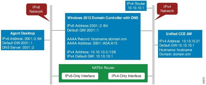
interface GigabitEthernet0/0
description ipv4-only interface
 ip address 10.10.10.81 255.255.255.128
 duplex auto
 speed auto
 nat64 enable
 no mop enabled

interface GigabitEthernet0/1
description ipv6-only interface
 no ip address
 duplex auto
 speed auto
 nat64 enable
 ipv6 address 2001::1/64
 ipv6 enable

ipv6 unicast-routing
ipv6 cef
!
nat64 prefix stateful 3001::/96
nat64 v4 pool POOL1 10.10.10.129 10.10.10.250
nat64 v6v4 list V6ACL1 pool POOL1 overload
ipv6 router rip RIPv6
!
ipv6 router rip RIP

!
ipv6 access-list V6ACL1
 permit ipv6 2001::/64 any
Configure DNS for IPv6
To meet the requirement that Unified CCE Administration be accessed by FQDN, a Forward lookup AAAA record for the Unified CCE AW-HDS-DDS servers and any External HDS servers must be created in DNS.
The steps in this procedure are for a Windows DNS server.
Procedure
|
Step 1 |
In Windows, navigate to Administrative Tools > DNS. This opens the DNS Manager. |
|
Step 2 |
In the Forward lookup zone, navigate to your deployment's domain name. |
|
Step 3 |
Right-click the domain name and select New Host (A or AAAA). |
|
Step 4 |
In the New Host dialog box, enter the computer name and IP address of the Unified CCE AW-HDS-DDS servers and any External HDS servers. Click Add Host. |
Determine IPv6 Translation of IPv4 Address for DNS Entry
You can determine the IPv6 address needed for the AAAA DNS record by running a ping command on any Windows machine using mixed notation. Type “ping -6” followed by your IPv6 Nat64 Prefix, two colons, and then the IPv4 address.
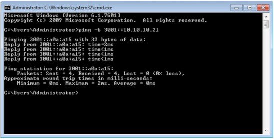
In the ping response, the IPv4 address is converted to the hexadecimal equivalent. Use this address in your static AAAA record.
Note |
Optionally, DNS64 can be used in place of static DNS entries. Use of DNS64 helps facilitate translation between IPv6 and IPv4 networks by synthesizing AAAA resource records from A resource records. The NAT64 Technology: Connecting IPv6 and IPv4 Networks technical paper gives an overview of DNS64 and how it is used with IPv6: https://www.cisco.com/c/en/us/products/collateral/ios-nx-os-software/enterprise-ipv6-solution/white_paper_c11-676278.html. |
Configure IPv6 on Unified CVP Call Server
For IPv6-enabled deployments, you must add an IPv6 address to your Unified CVP Call Server's existing network interface.
Perform this procedure only if you have an IPv6-enabled environment.
Procedure
|
Step 1 |
On the Unified CVP Call Server, navigate to . |
|
Step 2 |
Click Ethernet. |
|
Step 3 |
From the Ethernet Status window, select Properties. |
|
Step 4 |
Check the Internet Protocol Version 6 (TCP/IPv6) check box, and choose Properties. |
|
Step 5 |
Choose Use the following IPv6 address radio button. |
|
Step 6 |
Enter values in the IPv6 address, Subnet prefix length, and Default gateway fields. |
|
Step 7 |
Click OK and restart Windows when prompted. |
Configure Gateways to Support IPv6
For IPv6-enabled deployments, you must configure your Ingress and VXML gateways to enable IPv6 addressing.
Configure an Interface to Support IPv6 Protocol Stack
This procedure applies to both the Ingress and the VXML gateway.
Procedure
|
Configure the following on the Gateway: |
Enable ANAT in Ingress Gateway
Procedure
|
Configure the following on the Gateway: |
Enable Dual Stack in the Ingress Gateway
Procedure
|
Configure the following on the Gateway: |
Configure IPv6 on Unified Communications Manager
Cluster-Wide Configuration in Unified CM Administration
Perform the following procedure to set IPv6 as the addressing mode preference for media and signaling cluster-wide.
Procedure
|
Step 1 |
From Cisco Unified CM Administration, choose to configure the cluster-wide IPv6 settings for each Unified Communications Manager server. |
|
Step 2 |
From the Enable IPv6 drop-down list, choose True. |
|
Step 3 |
From the IP Addressing Mode Preference for Media drop-down list, choose IPv6. |
|
Step 4 |
From the IP Addressing Mode Preference for Signaling drop-down list, choose IPv6. |
|
Step 5 |
From the Allow Auto-configuration for Phones drop-down list, choose Off. |
|
Step 6 |
Save your changes. |
Transcoding
In an IPv6-enabled environment, a transcoder is required for the following scenarios:
-
An agent logged in to an IPv6 endpoint needs to send or receive transfers from an agent logged in to an IPv4 endpoint.
-
An agent logged in to an IPv6 endpoint needs to connect to a VXML Gateway for self service.
Add a Common Device Configuration Profile in Unified Communications Manager
In an IPv6-enabled environment, you may have both IPv4 and IPv6 devices.
Perform the following procedure to add an IPv4, IPv6, or dual stack common device configuration profile in Unified Communications Manager.
Procedure
|
Step 1 |
From Cisco Unified CM Administration, choose . |
|
Step 2 |
Click Add New and enter the name of the new common device configuration profile. |
|
Step 3 |
From the IP Addressing Mode drop-down list:
|
|
Step 4 |
Save your changes. |
Associate the Common Device Configuration Profile with Gateway Trunk
Perform the following procedure to associate the common device configuration profile with the Gateway trunk. This procedure applies to the Ingress Gateway.
Procedure
|
Step 1 |
From Cisco Unified CM Administration, choose . |
||
|
Step 2 |
Click Find. |
||
|
Step 3 |
From the Common Device Configuration drop-down list:
|
||
|
Step 4 |
Enter the IPv6 address in the Destination Address IPv6 field.
|
||
|
Step 5 |
Save your changes. |
Associate the Common Device Configuration Profile with an IPv4 or IPv6 Phone
Procedure
|
Step 1 |
From Cisco Unified CM Administration, choose . |
|
Step 2 |
Click Find. |
|
Step 3 |
From the Common Device Configuration drop-down list: choose the IPv6 common device configuration profile.
|
|
Step 4 |
Save your changes. |
Associate a SIP Profile in Unified CM
In an IPv6-enabled deployment, you must associate a SIP profile with the trunk you configured for Unified CVP.
Procedure
|
Step 1 |
From Cisco Unified CM Administration, choose . |
||
|
Step 2 |
Click Find. Choose the trunk profile that you want to view. |
||
|
Step 3 |
From the SIP Profile drop-down list, choose the SIP Profile you created.
|
||
|
Step 4 |
Save your change. |
Associate the Dual Stack Common Device Configuration Profile with SIP Trunk
Procedure
|
Step 1 |
From Cisco Unified CM Administration, choose . |
||
|
Step 2 |
Click Find. Choose the trunk profile that you want to view. |
||
|
Step 3 |
From the Common Device Configuration drop-down list, choose the Dual Stack Common Device Configuration Profile.
|
||
|
Step 4 |
Save your change. |
 Feedback