Cisco Unified Communications Manager System Guide, Release 10.0(1)
Bias-Free Language
The documentation set for this product strives to use bias-free language. For the purposes of this documentation set, bias-free is defined as language that does not imply discrimination based on age, disability, gender, racial identity, ethnic identity, sexual orientation, socioeconomic status, and intersectionality. Exceptions may be present in the documentation due to language that is hardcoded in the user interfaces of the product software, language used based on RFP documentation, or language that is used by a referenced third-party product. Learn more about how Cisco is using Inclusive Language.
- Updated:
- August 28, 2014
Chapter: Video Telephony
- Configure Video Telephony
- Introducing Video Telephony
- Video Calls
- Real-Time Transport Control Protocol Pass-Through
- Video Codecs
- Video Network
- Enabling an Audio-Only Device with Video
- H.323 Video
- Dynamic H.323 Addressing
- H.239-Extended Video Channels in H.323 Call
- Support for Third-Party H.323 Devices
- H.323 Devices Invoke Presentation Feature
- Opening Second Video Channels
- Call Admission Control (CAC) on Second Video Channels
- Number of Video Channels Allowed
- H.239 Commands and Indication Messages
- Topology and Protocol Interoperability Limitation
- Midcall Feature Limitation
- Skinny Client Control Protocol Video
- Skinny Client Control Protocol Video Bridging
- Video Over Wi-Fi
- Video for SNR Call
- SIP Video
- Cisco Video Conference Bridges
- Cisco TelePresence Video Communications Server
- Video Encryption
- Endpoint Support for the Binary Floor Control Protocol
- Presentation Sharing with the Binary Floor Control Protocol
- Bandwidth Management
- Call Admission Control
- Session Level Bandwidth Modifiers
- Video Resolution Support for SIP Phones
- RSVP
- Alternate Routing
- DSCP Marking
- Flexible DSCP Marking and Video Promotion
- Service Parameters for Flexible DSCP Marking and Video Promotion
- Configure Flexible DSCP Marking and Video Promotion Service Parameters
- Phone Configuration for Video Calls
- Additional Configuration for Video Calls
- Conference Control for Video Conferencing
- Video and Interoperability
- Far End Camera Control Protocol Support
- Video On Hold
Video Telephony
This chapter provides information about video telephony. Cisco Unified Communications Manager supports video telephony and thus unifies the world of voice and video calls. Video endpoints use Cisco Unified Communications Manager call-handling features and access a unified voice and video solution for dialing and connecting video calls.
The Cisco Unified Communications Manager video telephony solution offers these features:
-
Supports video and video-related features, such as far-end camera control (FECC)
-
Supports multiple logical channels that are needed to allow the transmission of video streams
-
Transmits midcall, media-related messages that are needed for video (that is, transmits commands or indications that are needed for video calls)
-
Supports H.323, Skinny Client Control Protocol (SCCP), and Session Initiation Protocol (SIP)
-
Enhances locations and regions to provide bandwidth management
-
Provides serviceability information, such as Call Detail Records (CDRs), about video calls
- Configure Video Telephony
- Introducing Video Telephony
- Video Telephony and Cisco Unified Serviceability
Configure Video Telephony
Cisco Unified Communications Manager supports video telephony and thus unifies the world of voice and video calls. Video endpoints use Cisco Unified Communications Manager call-handling features and access a unified voice and video solution for dialing and connecting video calls.
The Cisco Unified Communications Manager video telephony solution offers these features:
- Supports video and video-related features, such as far-end camera control (FECC)
- Supports multiple logical channels that are needed to allow the transmission of video streams
- Transmits midcall, media-related messages that are needed for video (that is, transmits commands or indications that are needed for video calls)
- Supports H.323, Skinny Client Control Protocol (SCCP), and Session Initiation Protocol (SIP)
- Enhances locations and regions to provide bandwidth management
- Provides serviceability information, such as Call Detail Records (CDRs), about video calls
To configure video telephony in Cisco Unified Communications Manager Administration follow these steps.
Introducing Video Telephony
The topics in the following section discuss the details of video telephony in the Cisco Unified Communications Manager environment.
- Video Calls
- Real-Time Transport Control Protocol Pass-Through
- Video Codecs
- Video Network
- Enabling an Audio-Only Device with Video
- H.323 Video
- Dynamic H.323 Addressing
- H.239-Extended Video Channels in H.323 Call
- Skinny Client Control Protocol Video
- Skinny Client Control Protocol Video Bridging
- Video Over Wi-Fi
- Video for SNR Call
- SIP Video
- Cisco Video Conference Bridges
- Cisco TelePresence Video Communications Server
- Video Encryption
- Endpoint Support for the Binary Floor Control Protocol
- Presentation Sharing with the Binary Floor Control Protocol
- Bandwidth Management
- Phone Configuration for Video Calls
- Additional Configuration for Video Calls
- Conference Control for Video Conferencing
- Video and Interoperability
- Far End Camera Control Protocol Support
- Video On Hold
Video Calls
The typical video call includes two or three Real-Time Protocol (RTP) streams in each direction (that is, four or six streams). The call can include the following stream types:
Video (H.261, H.263, H.263+, H.264-SVC, X-H.264UC, H.264-AVC, H.265, and Cisco VT Camera wideband video codecs)
-
Far-end camera control (FECC) (optional)
Binary Floor Control Protocols (BFCP)
Call control for video calls operates the same way as the call control that governs all other calls. See the Media Resources Overview.
 Note | See Intelligent Bridge Selection for details on how Cisco Unified Communications Manager can allocate a video conference bridge automatically. |
Real-Time Transport Control Protocol Pass-Through
Real-Time Transport Control Protocol Pass-Through in MTP Topologies
An IOS Media Terminating Point (MTP) prior to 15.2(2)T, cannot pass-through Real-Time Transport Control Protocol (RTCP) packets and therefore cannot exchange Real-Time Protocol (RTP) feedback data to enhance the RTP transmission. The primary function of RTCP is to provide feedback of media distribution by periodically sending statistics to participants in a streaming multimedia session. RTCP gathers statistics for a media connection and information such as transmitted octet and packet counts, lost packet counts, jitter, and round-trip delay time. An application may use this information to control quality of service parameters, perhaps by limiting flow, or using a different codec.
IOS MTP Version 15.2(2)T and later supports RTCP pass-through capability so that the endpoint in a call with an MTP present can still provide feedback and status on an RTP transmission. RTCP pass-through capability applies on media channels.
The RTCP pass-through feature is not limited to a specific call signaling protocol. For example it can be SIP-SIP, SIP-nonSIP, or nonSIP-nonSIP.
In order for Cisco Unified CM to allocate an RTCP pass-through capable MTP specifically, the call needs to fulfill the following conditions:
An MTP is requested for a feature that requires the MTP to be in media pass-through mode. For example, TRP, DTMF translation, IP address V4/V6 translation, etc. RTCP pass-through is only applicable when media is in pass-through mode
The RTCP pass-through MTP needs to be included in the Media Resource Group Lists (MRGL) of the endpoint that sponsors the MTP. MTP can be inserted by RSVP, E2ERSVP, TRP, DTMF mismatch reasons.
When the call is capable of establishing video channels, Cisco Unified CM attempts to search for an RTCP pass-through capable MTP. For example, Cisco Unified CM picks an RTCP pass through capable MTP from other non-capable ones in the MRGL. If an RTCP pass-through capable MTP is not available, then Cisco Unified CM stills allocates an MTP for the call.
When the call is capable of establishing an audio channel only, Cisco Unified CM does not intentionally requests an RTCP-pass-through capable MTP for the non-video call. However, if the MRGL only contains RTCP-pass-through capable MTP(s), then Cisco Unified CM inserts one of those to the audio call.
In order to have an RTCP pass-through capable MTP, the call also needs to fulfill the current CAC bandwidth for video call.
Note | If a call initially establishes with a non-RTCP pass-through capable MTP (prior to version 15.2(2)T) present in the call , and the call escalates into a video capable call, Cisco Unified CM does not reallocate to an RTCP-pass-through capable MTP. In that case, even though the call has been escalated to a video call, the existing MTP does not allow RTCP packets to be passed through. |
Video Codecs
Common video codecs include H.261, an older video codec, H.263, a newer codec that gets used to provide internet protocol (IP) video, and H.264, a high-quality codec. The system supports H.264 for calls that use the Skinny Client Control Protocol (SCCP), H.323, and SIP on originating and terminating endpoints only. The system also supports regions and locations.
Release 10.01 introduces H.265 High Efficiency Video Codec (HEVC), H.264 Scalable Video Codec (SVC), and X-H.264UC (Lync) video codecs which are supported in SIP protocols only.
H. 264 SVC is a new annex to H.264-AVC video compression standard; meaning it is an enhancement on top of H.264-AVC. It provides the ability to encapsulate multiple video streams at various frame-rates and resolutions in one container.
H.261 and H.263 codecs exhibit the following parameters and typical values:
-
Bit rates range from 64 kb/s to a few mb/s. These bit rates can exist in any multiple of 100 b/s. H.261 and H.263 can function with bit rates lower than 64 kb/s, but video quality suffers in such cases.
-
Resolution:
-
Frame Rate: 15 frames per second (fps), 30 fps
-
Annexes: F, D, I, J,K, L, P, T, N
Cisco Unified Video Advantage (CUVA) supports the H.263 and H.264 codecs that can be used for intracluster and intercluster calls, respectively. Correct configuration with related capabilities and regions provides basis for support. This support also applies to mid-call.
The bandwidth of video calls equals the sum of the audio bandwidth and the video bandwidth. The total bandwidth does not include overhead.
Example
A 384-kb/s video call may comprise G.711 at 64 kb/s (for audio) plus 320 kb/s (for video). This sum does not include overhead. If the audio codec for a video call is G.729 (at 24 kb/s), the video rate increases to maintain a total bandwidth of 384 kb/s. If the call involves an H.323 endpoint, the H.323 endpoint may use less than the total video bandwidth that is available. Regardless of protocol, the endpoint may always choose to send at less than the max bit rate for the call.
Video Network
The figure which follows provides an example of a video network that uses a single Cisco Unified Communications Manager cluster. In a successful video network, any endpoint can call any other endpoint. Video availability only exists if both endpoints are video enabled. Video capabilities extend across trunks.
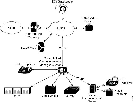
The Cisco video conference portfolio comprises the following video bridges:
The Cisco UC Endpoints portfolio comprises the following endpoints that support video:
-
Cisco Unified IP Phone 9971
-
Cisco Unified IP Phone 9951
-
Cisco Unified IP Phone 8941
-
Cisco Unified IP Phone 8945
-
Cisco Unified IP Phone 7985
-
Cisco IP Video Phone E20
-
Cisco TelePresence EX60
-
Cisco TelePresence EX90
-
Cisco TelePresence Quick Set C20
-
Cisco TelePresence Codec C40
-
Cisco TelePresence Codec C60
-
Cisco TelePresence Codec C90
Cisco TelePresence 1000
Cisco TelePresence 1100
Cisco TelePresence 1300-47
Cisco TelePresence 1300-65
Cisco TelePresence 1310-65
Cisco TelePresence 3000
Cisco TelePresence 3200
Cisco TelePresence 500-32
Cisco TelePresence 500-37
Cisco TelePresence MX200
Cisco TelePresence MX300
Cisco TelePresence TX9000
Cisco TelePresence TX9200
For more information, refer to the applicable IP phone user and administration guide.
Note | Third-party SIP video endpoints are capable of connecting to Cisco Unified Communications Manager as a line-side device or as a trunk-side device. For more information, see Third-Party SIP Endpoints. |
Enabling an Audio-Only Device with Video
You can enable an IPv4-only audio-only device with video by using a Cisco application, Cisco Unified Video Advantage. You can associate the application with a Cisco Unified IP Phone in order to display the video component on your PC or laptop. This association can occur before a call is made or during a call (mid-call). Cisco Unified IP Phones, such as 7975, 7940, 7960, 7975, 6961, 6941, and 6921 support Cisco Unified Video Advantage.
For example, a call occurs from a Cisco Unified IP Phone 7975 to a video phone. The call gets established as audio only. After Cisco Unified Video Advantage is associated with the Cisco Unified IP Phone 7975, the call gets reestablished as a video call.
During the association, Cisco Unified Communications Manager receives updated capabilities for the phone via existing SCCP messages. After the updated capabilities are received, Cisco Unified Communications Manager negotiates for video.
If the initial call involves an IP phone without a video, only audio location bandwidth gets reserved, and the media layer establishes an audio-only call.
In addition to audio phones, Cisco video phones, such as 9971 and 9951 also support Cisco Unified Video Advantage.
H.323 Video
H.323 video exhibits the following characteristics:
H.323 endpoints can be configured as H.323 phones, H.323 gateways, or H.323 trunks.
Call forwarding, dial plan, and other call-routing-related features work with H.323 endpoints.
H.323 video endpoints cannot initiate hold, resume, transfer, park, and other similar features.
If an H.323 endpoint supports the empty capability set (ECS), the endpoint can be held, parked, and so forth.
Some vendors implement call setup in such a way that they cannot increase the bandwidth of a call when the call gets transferred or redirected. In such cases, if the initial call is audio, users may not receive video when they are transferred to a video endpoint.
No video media termination point (MTP) nor video transcoder currently exists. If an audio transcoder or MTP is inserted into a call, that call will be audio only. This is true when the IPVC audio transcoding capabilities is not being used. When the IPVC transcoders are used, you can transcode the audio and send/receive video.
For H.323 video calls, users must specify video call bandwidth.
Dynamic H.323 Addressing
You can configure a H.323 client with the E.164 address that is registered with the gatekeeper. E.164 addressing facilitates H.323 configuration and call routing by allowing the Cisco Unified Communications Manager to route all calls in place of the gatekeeper. The gatekeeper that is to be configured requires the following characteristics:
Registering with the Gatekeeper
At boot time, Cisco Unified Communications Manager loads static configuration information such as the E.164 address and the configured gatekeeper for each H.323 client. The H.323 clients in the same gatekeeper zone stay in one group. A registration with the gatekeeper gets initiated for the group. The process does not require individual registration for each member of the group.
H.323 clients that belong to the same gatekeeper and zone belong to the same group, and only one registration is initiated for this group. H.323 devices that belong to the same gatekeeper as the first group but to a different gatekeeper zone are part of another group, and only one registration is initiated for this group. All members of the same group use the same technology prefix.
Call Processing
During an outbound call where the H.323 client is the called party, Cisco Unified Communications Manager routes the call on the basis of DN to the H.323 device. Cisco Unified Communications Manager uses the H.323 device configuration to determine whether the gatekeeper is configured and sends an Admission Request Message (ARQ) with the configured E.164 address. If the device is registered with the gatekeeper, the gatekeeper sends an Admission Confirm Message (ACF) with the device's current IP address. Cisco Unified Communications Manager routes the call directly to this address.
During an inbound call where the H.323 device is the calling party, the gatekeeper routes the call to Cisco Unified Communications Manager. Cisco Unified Communications Manager uses the source E.164 address to determine whether the calling device is configured. Cisco Unified Communications Manager uses the configuration to determine the configuration for that phone. The phone configuration includes regions, locations, MRGL, and so on.
Be aware of the following items:
-
The system does not support E.164 addressing on H.323 trunks, intercluster trunks, and H.323 gateways.
-
Cisco Unified Communications Manager does not resolve the device name when a gatekeeper-controlled H.323 client is configured. Cisco Unified Communications Manager can access the gatekeeper field for the H.323 client to discover the device. This enables Cisco Unified Communications Manager to bypass name resolution for the device name.
-
Cisco Unified Communications Manager supports a maximum of one E.164 number per gatekeeper-controlled H.323 client. If the gatekeeper field is populated, you cannot configure a second DN. If an H.323 client is configured for more than one DN, you cannot add the extra gatekeeper information to the database.
-
The Gatekeeper routes call by using zone information when there is no zone prefix.
Configuration Notes
Be aware of the following items for configuration purposes:
-
You must ensure that gatekeeper is configured in Cisco Unified Communications Manager before an H.323 client can specify that gatekeeper in its configuration. The Gatekeeper field stays empty by default.
-
Be sure to add the gatekeeper name, technology prefix, zone, and E.164 fields to the H.323 client configuration. You do not need to add Terminal Type. Default specifies the gateway type. If the gatekeeper is not chosen for the gatekeeper field during configuration of each of these fields, these fields cannot populate.
-
Gatekeeper, zone, technology prefix fields, and E.164 information display under the Gatekeeper Information group on H.323 Client configuration.
-
When an H.323 client uses the same gatekeeper, zone and technology prefix as those of another client, consider both clients in the same group. This group represents a single endpoint to the gatekeeper.
-
You cannot use the same zone name for the H.323 client and trunk. A zone that an H.323 client uses must differ from the one that an H.323 trunk or a gatekeeper-controlled intercluster trunk uses.
-
Ensure the service parameter, Send Product Id and Version ID, is set to True.
If an H.323 client is configured with an E.164 address and a gatekeeper, the database stores this information when the configuration is updated. This information gets loaded at boot time or when the device is reset.
H.239-Extended Video Channels in H.323 Call
The extended video channels feature works via H.239 protocol and enables multiple video channel support. Cisco Unified Communications Manager supports negotiating an extended video channel using the H.239 protocol in direct point-to-point H.323 calls. This also includes calls across the H.323 intercluster trunk.
Cisco Unified Communications Manager supports all H.239 associated support signals and commands that are specified in the H.239 recommendation.
The following sections describes characteristics which apply to the extended video channels feature.
- Support for Third-Party H.323 Devices
- H.323 Devices Invoke Presentation Feature
- Opening Second Video Channels
- Call Admission Control (CAC) on Second Video Channels
- Number of Video Channels Allowed
- H.239 Commands and Indication Messages
- Topology and Protocol Interoperability Limitation
- Midcall Feature Limitation
Support for Third-Party H.323 Devices
The extended video channel feature supports H.239 interoperability among third-party video endpoints and Cisco Unified Voice Conferencing. Cisco Unified Communications Manager allows an extended video channel to be used for presentation and live meeting transmission. This feature focuses on multiple video channel support via H.245 signaling. The following presentation applications provide basis for this multichannel support:
Natural Presenter package by the third-party vendor Tandberg
People + Content by the third-party vendor Polycom
Both Natural Presenter package and People + Content use the H.239 protocol to negotiate capabilities and define the roles of the additional video channels.
Note | Natural Presenter package by Tandberg and People + Content by Polycom only support H.239 for the presentation mode. |
Note | Be aware that the presentation applications that are offered by Tandberg and Polycom are optional features. You must have one of these options and H.239 enabled in both caller and callee endpoints to negotiate second video channels or the call will be limited to a single video channel. |
H.323 Devices Invoke Presentation Feature
Tandberg and Polycom video endpoints allow the user to share presentation materials from various components (for example, VCR, Projector, PC, and so on). The components can physically connect with the endpoints, and the PC can also run presentation applications that are provided by the vendor to transmit the presentation image. The source of presentation and the component connection with the video endpoint are irrelevant to the mechanism of establishing video channels by using H.239.
Note | For details on setting up presentation sources, see the video endpoint user guide. |
When two H.239-enabled endpoints attempt to establish a video call, they declare their video capabilities for the main video channel for meeting participants and their extended video capabilities (H.239 capabilities) for the second video channel. The following contents comprise H.239 capability signals:
-
The endpoints send signals to indicate that the devices support H.239. They also send associated commands and indication signals for managing the second video channel. This enables both the endpoints to be aware that the call is capable of opening multiple video channels.
-
The endpoints sends out one or more extended video codec capabilities to express video codec capabilities for second channels. The endpoint must specify the role of the second video channel. The defined role labels can be
After the capabilities have been exchanged, both endpoints immediately open two-way audio channels and the main video channels as in the traditional video calls.
Opening Second Video Channels
Depending on the third-party endpoint implementation, the second video channel is handled differently among vendors.
Natural Presenter Package by Tandberg
Tandberg initiates the second video channel on demand. A Tandberg device does not open the second video channel immediately after the main video channel is established. The second channel gets opened when one of the callers (the presenter) specifies the source of the presentation and invokes a command to start the presentation.
When a Tandberg user decides to start sharing the presentation, Tandberg requests the other call party to open an extended video channel for receiving the presentation image; therefore, a Tandberg-Tandberg call has only one-way second video channel.
People + Content by Polycom
Unlike Tandberg, a Polycom video endpoint initiates the second video endpoint immediately as a part of the default mechanism, after both parties have confirmed that additional video channels can be supported.
Note | The channel established gets automatically if both parties support H.239 and have the extended video channel feature enabled. However, the additional channel does not show anything until one of the parties start to share presentation. |
Polycom initiates a request for the second video channel to the other call party regardless of the usage of the second video channel; therefore, in a Polycom-Polycom call, two-way video channels get opened between the devices even if only one of them sends out presentation image/video.
This implementation ensures that both call parties have the second video channel ready for transmission when the call parties decide to take the token to present something. Although one of the two video channels remains idle (not sending anything), the Polycom device controls bandwidth to ensure load efficiency.
Note | This difference in handling second video channels does not affect the implementation of H.239. Cisco Unified Communications Manager does not initiate any receiving channel request in an H.323-H.323 call. Cisco Unified Communications Manager simply relays all channel requests from one terminal to another. |
Note | Cisco Unified Communications Manager does not enforce two-way transmission for the second set of video channels because this does not represent a requirement in the H.239 protocol. |
Call Admission Control (CAC) on Second Video Channels
The following call admission control policies of Cisco Unified Communications Manager get applied to the second video channels:
Cisco Unified Communications Manager restricts the bandwidth usage by the second video channels on the basis of location configuration. When the second video channel is being established, Cisco Unified Communications Manager makes sure that enough video bandwidth stays available within the location pool and reserves bandwidth accordingly. If the required bandwidth is not available, Cisco Unified Communications Manager instructs the channel to reduce the available bandwidth to zero.
No change occurs in the region configuration or policies to support the second video channels.
Traditionally, Cisco Unified Communications Manager region policy has only supported a call with a single video channel and the total bandwidth usage of this call never gets larger than what the region configuration specifies.
If the administrator sets a finite region video bandwidth restriction for an H.239 call, Cisco Unified Communications Manager will violate the region policy because the region value will get used against the bandwidth that is requested for each video channel independently.
Example
If the region video bandwidth is set to 384Kbps and the audio channel uses 64Kb/s,
the maximum allowed bandwidth for each video channel will be (384Kb/s - 64Kb/s)= 320Kb/s.
i.e. the maximum bandwidth to be used by the H.239 call will be (audio bw + 2*(384 - audio
bw)) = 704Kb/s, which goes beyond the 384Kb/s bandwidth that the region specifies.
Note | You should consider relaxing both region and location bandwidth restrictions for H.239 calls, so the H.239 devices are allowed to readjust and balance load for both the video channels without Cisco Unified Communications Manager intervention. |
Number of Video Channels Allowed
Cisco Unified Communications Manager supports only a maximum of two video channels due to the following reasons:
H.239 Commands and Indication Messages
Command and Indication (C&I) messages get used for H.239 to manage tokens for the Presentation and Live roles and to permit devices to request release of video flow control to enable the operation of additional media channels. Cisco Unified Communications Manager supports all the C & I messages. Whenever Cisco Unified Communications Manager receives C&I messages, it relays them to the call party accordingly.
Be aware that the flow control release request and response messages can be used to request that the far end release flow control, so it allows an endpoint to send the indicated channel at the indicated bit rate.
Note | Be aware that the call party may or may not honor the request as is indicated by flow control release response. |
The Presentation role token messages allow an H.239 device to acquire the token for presentation. The other call party may accept or reject the request. The presenter device sends out a token release message when it is no longer needed.
Topology and Protocol Interoperability Limitation
Cisco Unified Communications Manager supports only H.239 in H.323 to H.323 calls. Cisco Unified Communications Manager allows H.239 calls to be established across H.323 intercluster trunk or multiple nodes. If an H.239-enabled device attempts to make a call with a non-H323 end, the H.239 capabilities will get ignored and the call will get conducted like the traditional video calls that are supported by Cisco Unified Communications Manager.
Cisco Unified Communications Manager does not support a second video channel when a media termination point or transcoder is inserted into the call. If it happens, the call will fall back to normal video calls.
Midcall Feature Limitation
Cisco Unified Communications Manager supports opening second video channels only in direct H.323 to H.323 calls.
 Caution | Do not attempt to invoke any midcall features such as call transfer or hold/resume operations. Doing so can lead to problems and the second video channel can get disconnected. |
Skinny Client Control Protocol Video
Skinny Client Control Protocol video exhibits the following characteristics:
If a phone that is running Skinny Client Control Protocol reports video capabilities, Cisco Unified Communications Manager automatically opens a video channel if the other end supports video.
For Skinny Client Control Protocol video calls, system administration determines video call bandwidth by using regions. The system does not ask users for bit rate.
Skinny Client Control Protocol Video Bridging
Video conferencing requires a Skinny Client Control Protocol video bridge. Skinny Client Control Protocol video bridging exhibits the following characteristics:
-
Skinny Client Control Protocol video bridging requires the same setup as an audio bridge.
-
Skinny Client Control Protocol video bridging supports a mix of audio and video in a conference.
-
Media resource group lists determine whether an endpoint receives an audio or video bridge. That is, the media resource group list configuration of the user who sets up the conference determines whether the conference is a video conference or an audio-only conference.
Video Over Wi-Fi
With a dual mode smart client running on a video-capable smart phone and registered to Cisco Unified Communications Manager, a video call can take place between the smart phone and another video capable end point over VoIP.
If a Cisco Dual Mode for iPhone (TCT) is video capable, it can call another video capable end point through the Cisco Unified Communications Manager over IP.
A video enable/disable toggle option is available on the device page of CCMAdmin. Additionally, mid-call features like Hold/Resume, conference, transfer with video are available.
MTP Interactions and Limitations
A software MTP allocated in the call, does not support video streaming.
A hardware multimedia MTP allocated allows video, with the condition that MTP allocated due to transcoder, TRP check on devices/trunks/gateways, video is not supported.
When Unified Mobility requires the MTP for DTMF detection, video is available.
MTP allocated due to transcoder, TRP check on devices/trunks/gateways, video will be available.
Video for SNR Call
Phone A (video capable) and Phone B are in cluster 1.
Phone C (video capable) is the remote destination shared line with Phone B is in cluster 2.
Phone A calls Phone B.
Phone C rings because of Single Number Reach.
If you pick up Phone C and both Phone A and Phone C are video capable, then a video call takes place.
Limitations and Conditions
If in the entire call setup, Cisco Unified Communications Manager allocates a software MTP, then video streaming is not supported because MTP does not support video streaming.
A hardware multimedia IOS MTP allocated in the call may result in video with certain conditions :
If the MTP is allocated because of MTP Required check on trunks and gateways, then video streaming does not occur.
If Unified Mobility requires MTP for DTMF detection, video is not available.
If MTP is allocated due to transcoder and a TRP check on devices, trunks, and gateways, video is available.
SIP Video
SIP video supports the following video calls by using the SIP Signaling Interface (SSI):
-
SIP to SIP
-
SIP to H.323
-
SIP to SCCP
-
SIP intercluster trunk
-
H.323 trunk
-
Combination of SIP and H.323 trunk
SIP video calls also provide media control functions for video conferencing.
Cisco Unified Communications Manager video supports SIP on both SIP trunks and lines support video signaling. SIP supports the H.261, H.263, H.263+, H.264 (AVC), H.264 (SVC), X-H.264UC (Lync), and H.265 video codecs (it does not support the wideband video codec that the VTA uses).
The Media Termination Point (MTP), which is used for RFC 2833, supports multiple logical channels within a session. A logical channel could exist for audio or video. To support video channels, the MTP uses pass-through mode. Video pass-through gets enabled if the MTP supports both pass-through and multiple logical channels. Not all MTP devices support multiple logical channels and pass-through mode.
Configuring SIP Devices for Video Calls
Perform the following steps to enable video calls on SIP devices:
SIP Trunks
Cisco Unified IP Phone 9951 and 9971
-
On the Phone Configuration window in Cisco Unified Communications Manager Administration, set the Cisco Camera and Video Capabilities product specific configuration to Enabled.
-
Reset the phone.
For more information, see the Cisco Unified IP Phone 8961, 9951, 9971 User Guide for Cisco Unified Communications Manager (SIP).
Third-Party SIP Endpoints
Cisco Video Conference Bridges
Cisco Unified Communications Manager supports a variety of solutions for video conferencing. The following video conference bridges support ad hoc and meet-me video conferencing:
- Cisco TelePresence MCU Video Conference Bridge
- Cisco TelePresence Conductor Video Conference Bridge
- Cisco Unified MeetingPlace Video Conference Bridge
Cisco TelePresence MCU Video Conference Bridge
Cisco TelePresence MCU is a set of hardware conference bridges for Cisco Unified Communications Manager.
The Cisco TelePresence MCU is a high-definition (HD) multipoint video conferencing bridge. It delivers up to 1080p at 30 frames per second, full continuous presence for all conferences, full transcoding, and is ideal for mixed HD endpoint environments. The Cisco TelePresence MCU supports SIP as the signaling call control protocol. It has a built in Web Server that allows for complete configuration, control, and monitoring of the system and conferences. The Cisco TelePresence MCU provides XML management API over HTTP.
Cisco TelePresence MCU allows both ad hoc and meet-me voice and video conferencing. Each conference bridge can host several simultaneous, multiparty conferences. Cisco TelePresence MCU must be configured in Port Reservation mode.
Cisco TelePresence Conductor Video Conference Bridge
Cisco TelePresence Conductor provides intelligent conference administrative controls and is scalable, supporting device clustering for load balancing across MCUs and multiple device availability. Administrators can implement the Cisco TelePresence Conductor as either an appliance or a virtualized application on VMware with support for Cisco Unified Computing System (Cisco UCS) platforms or third-party-based platforms. Multiway conferencing, that allows for dynamic two-way to three-way conferencing, is also supported.
Cisco TelePresence Conductor supports both ad hoc and meet-me voice and video conferencing. Cisco TelePresence Conductor dynamically selects the most appropriate Cisco TelePresence resource for each new conference. Ad hoc, “MeetMe” and scheduled voice and video conferences can dynamically grow and exceed the capacity of individual MCUs. One Cisco TelePresence Conductor appliance or Cisco TelePresence Conductor cluster has a system capacity of 30 MCUs or 2400 MCU ports. Up to three Cisco TelePresence Conductor appliances or virtualized applications may be clustered to provide greater resilience.
Cisco Unified MeetingPlace Video Conference Bridge
Cisco Unified MeetingPlace is a comprehensive collaboration solution that can be configured to act as a video conference bridge that supports both ad hoc and meet-me video conferencing. Cisco Unified MeetingPlace also integrates with Cisco WebEx to provide a variety of web conferencing and content-sharing solutions.
Cisco Unified MeetingPlace deployments vary in size and complexity. The solution may be housed on a single server, or on multiple servers. All Cisco Unified MeetingPlace deployments include an Application Server, which is installed on a Cisco MCS. The Application Server controls the media servers of the solution.
Video conferencing functionality is provided by the media server. The Cisco Unified MeetingPlace solution provides two media server options: an Express Media Server and a Hardware Media Server. The Express Media Server is a software-based media server that is installed on the Application Server, thereby allowing for a single-box deployment. The Hardware Media Server consists of audio and video blades installed on a separate Cisco 3500 series media server.
For web deployments, an optional web server may also be included.
Conferencing Capabilities
If Cisco Unified MeetingPlace is configured as a conference bridge, and the Express Media Server deployment is used, the conference bridge supports both ad-hoc and meet-me video conferencing. The Express Media Server supports both the H.263 and H.264/AVC video codecs, but transcoding between different codecs within a single meeting is not supported.
With the Express Media Server, the video mode, which specifies the display resolution, must be set before the conference begins. For ad-hoc conferencing, all ad-hoc meetings share a single system-wide setting. If you want legacy CIF endpoints to participate in ad hoc video conferences, then all ad-hoc meetings must be limited to CIF resolution of 352 x 288.
If the Hardware Media Server deployment is used, the conference bridge supports meet-me video conferencing only. Transcoding between video codecs is supported. Additionally, participants can record the audio and video portions of meetings.
The following table summarizes the main videoconferencing features available in Cisco Unified MeetingPlace. Please note that overall conferencing capacity depends on a variety of factors, including the configuration settings as well as the physical hardware. Overall capacity is highest for lower resolution video along with a low bandwidth audio codec, such as G.711. Using high-definition video or a high bandwidth audio codec will result in lower capacity.
For more detailed information on the capabilities of Cisco Unified MeetingPlace, refer to the Cisco Unified MeetingPlace product documentation.
| Feature | Express Media Server | Hardware Media Server | ||
|---|---|---|---|---|
| Conferencing | Ad hoc and meet-me | Meet-me | ||
| Audio codecs | G.711 G.722 G.729a |
G.711 G.722 G.729a iLBC |
||
| Video codecs | H.263 H.264/AVC |
H.261 H.263 H.264/AVC |
||
| Recording | Cannot record the video | Can record both audio and video portion of meetings | ||
| Transcoding between H.264 and H.263AVC | Not supported in same meeting, although both codecs are supported | Supported | ||
| Video resolution | Up to 1280x720 | 352 x 288 | ||
| Total number of callers | Up to 1300 for audio Up to 650 for video
|
Up to 2000 for audio Up to 300 for video |
Cisco TelePresence Video Communications Server
Cisco Unified Communications Manager can interoperate with a Cisco TelePresence Video Communications Server (VCS). To make the two systems compatible, you must configure a SIP normalization script on the SIP trunk that connects Cisco Unified Communications Manager to the Cisco VCS. The normalization script adjusts the SIP signaling so that the two products can communicate.
Cisco TelePresence Video Communication Server provides advanced telepresence and video conferencing call control for the Cisco TelePresence line of products. It enables any-to-any interoperability between all standards-compliant SIP and H.323 devices and offers three deployment options:
As a Server Control, Cisco TelePresence Video Communication Server provides advanced telepresence applications and session management to all standards-compliant telepresence endpoints, infrastructure, and management solutions. Cisco VCS Control provides Session Initiation Protocol (SIP) proxy and H.323 gatekeeper services.
As a Server Expressway, Cisco TelePresence Video Communication Server provides standards-based and secure firewall traversal for SIP and H.323 devices. Cisco VCS Expressway enables business-to-business communications, empowers remote and home-based workers, and allows service providers to provide video communications to customers.
In the Starter Pack Express deployment, Cisco TelePresence Video Communication Server provides an all-in-one solution targeted to customers who are deploying small to medium-sized Cisco TelePresence systems for the first time
Configure Interoperability with Cisco TelePresence Video Communications Server
To enable Cisco Unified Communications Manager to interoperate with a Cisco VCS, perform the following steps on the SIP trunk that connects Cisco Unified Communications Manager to Cisco VCS
| Step 1 | In Cisco Unified Communications Manager Administration, choose . |
| Step 2 | Choose the SIP trunk that connects Cisco Unified Communications Manager to the Cisco VCS. |
| Step 3 | In the SIP Profile drop-down list box, choose Standard SIP Profile for VCS. |
| Step 4 | In the Normalization Script drop-down list box, choose vcs-interop. |
| Step 5 | the Normalization Script area, leave the Parameter Name and Parameter Value fields empty. If these fields are already populated, delete the contents of the field. |
Video Encryption
Cisco Unified Communications Manager supports encryption of audio, video, and other media streams so long as the individual endpoints involved in the communication also support encryption. Cisco Unified Communications Manager uses the Secure Real-Time Transport Protocol (SRTP) to encrypt the media streams. Some of the features include:
-
Support for SIP and H.323 endpoints
-
Support for encryption of main audio and video line while operating in Media Termination Point (MTP) passthru mode
-
Support for multiple encryption methods
-
Support for Session Description Protocol (SDP) crypto-suite session parameters in accordance with RFC 4568
To provide encrypted communications, encryption keys are exchanged between the endpoints and Cisco Unified Communications Manager during the SIP call setup. For this reason, the SIP signaling should be encrypted using TLS. During the initial call setup, the video endpoints exchange a list of encryption methods they support, select an encryption suite supported by both endpoints, and exchange encryption keys. If the endpoints cannot agree on a common encryption suite, the media streams are unencrypted and transported using the Real-Time Transport Protocol (RTP).
Note | If the individual endpoints do not support encryption, the communication will take place using RTP. |
Encryption Methods
Cisco Unified Communications Manager supports different encryption suites. The encryption method is identified using the Crypto-suite option in the SDP portion of the SIP message. The following table shows which SDP encryption suites are supported by Cisco Unified Communications Manager.
Encryption Standard |
Description |
|---|---|
AES_CM_128_HMAC_SHA1_80 |
128-bit encryption key and an 80-bit message authentication tag |
AES_CM_128_HMAC_SHA1_32 |
128-bit encryption key and a 32-bit message authentication tag |
F8_128_HMAC_SHA1_80 |
128-bit encryption key and an 80-bit message authentication tag |
In addition to the above methods, Cisco Unified Communications Manager also supports DTLS encryption of media streams.
Negotiation of the Encryption Method
The selection of the encryption method to be used for an individual call is made according to which encryption suites are available on the individual endpoints themselves. If the endpoints cannot agree on an encryption method, then media is not be encrypted and is transported using RTP.
Cisco Unified Communications Manager uses the SIP Offer/Answer model to establish SIP sessions, as defined in RFC 3264. In this context, a calling device makes an Offer contained within the SDP fields in the body of a SIP message. The Offer typically defines the media characteristics supported by the device, including the encryption method that is supported by that device, as well as media streams, codecs, IP addresses, and ports to use.
The receiving device responds with an Answer in the SDP fields of its SIP response, with its own corresponding encryption suites, matching media streams, codecs, and the IP address and port on which to receive the media streams. Cisco Unified Communications Manager uses this Offer/Answer model to establish SIP sessions as defined in the key SIP standard, RFC 3261.
The operation of the SIP Offer/Answer model can differ depending on the features. The process is slightly different for Early Offer and Delayed Offer:
In an Early Offer session, the called device selects the appropriate encryption suite. In this case, the calling device sends its preferred encryption suites in the original SIP invite message. The called device compares the list of encryption methods offered by the caller to its own list of available encryption methods, and selects the best option. Re-Invites will be handled the same as Early Offer.
In a Delayed Offer session, the calling device includes a list of supported encryption methods. When it receives the initial invite, Cisco Unified Communications Manager forwards the INVITE on to the called device without the SDP portion that contains the encryption methods. The called device responds with its own list of encryption methods. Cisco Unified Communications Manager compares the two lists and selects an appropriate encryption method that is supported by both endpoints.
Limitations
Cisco Unified Communications Manager has the following limitations with video encryption:
Cisco Unified Communications Manager does not provide support for the UNENCRYPTED_RTP SDP crypto-line parameter. The call is downgraded to RTP if no other SDP crypto-line parameters are present.
If the SDP offer contains multiple keys, only the first key is used. The other keys are dropped and the call continues using only the first key.
Supported Protocols
The following table shows which encryption methods are supported when specific signaling methods are used.
|
Scenario |
Support |
|---|---|
|
SIP-SCCP |
Video encryption is not supported over SCCP. |
|
SIP-SIP using MTP/RSVP/TRP |
Video encryption is supported. However, in MTP passthru mode only main audio and video lines are encrypted. |
|
SIP-SIP over H.323 ICT |
Video encryption is not supported over H.323 trunks. Only audio encryption is supported. |
|
SIP-H.323 |
Video encryption is not supported for calls from SIP to H.323 endpoints. |
|
H.323-H.323 |
Video encryption is supported using H.235. |
Endpoint Support for the Binary Floor Control Protocol
Cisco Unified Communications Manager 8.6(2) provides support for the Binary Floor Control Protocol (BFCP) for specific Cisco and third-party video endpoints. BFCP allows users to share a presentation within an ongoing video conversation.
The following example shows how presentation sharing using BFCP works:
An ongoing video conversation exists between two video phones. User A decides to show User B a slide presentation that is saved on a laptop. User A attaches the laptop to a Cisco EX90 video phone and presses the Present button on the phone. The SIP INVITE message gets initiated to the other phone, forming the invitation for a BFCP stream. After the BFCP session is negotiated, an additional stream is added to the audio and video streams. The BFCP stream allows User B to see the desktop on User A's laptop.
BFCP Support on Cisco Video Endpoints
For the following Cisco video endpoints, BFCP is enabled by default through the endpoint Qualification and Evaluation of device (QED) settings. Because BFCP is automatically enabled, Cisco Unified Communications Manager does not provide configuration options for these endpoints.
Cisco E20
Cisco TelePresence Codec C40
Cisco TelePresence Codec C60
Cisco TelePresence Codec C90
Cisco TelePresence EX60
Cisco TelePresence EX90
Cisco TelePresence Quick Set C20
Cisco TelePresence Profile 42 (C20)
Cisco TelePresence Profile 42 (C60)
Cisco TelePresence Profile 52 (C40)
Cisco TelePresence Profile 52 Dual (C60)
Cisco TelePresence Profile 65 (C60)
Cisco TelePresence Profile 65 Dual (C90)
Cisco TelePresence
Cisco TelePresence 1000
Cisco TelePresence 1100
Cisco TelePresence 1300-47
Cisco TelePresence 1300-65
Cisco TelePresence 1310-65
Cisco TelePresence 3000
Cisco TelePresence 3200
Cisco TelePresence 500-32
Cisco TelePresence 500-37
BFCP Support on Third-Party Phones
For the following third-party video endpoints, BFCP is disabled by default, but support can be enabled in the Protocol Specific Information section of the Phone Configuration window:
Cisco Unified Communications Manager Administration Configuration Tips
Presentation sharing using BFCP is supported only on full SIP networks. The entire network, including the endpoints and all the intermediary devices and trunks, must be SIP. BFCP must be enabled on all SIP trunks and lines.
To configure BFCP on SIP trunks, check the Allow Presentation Sharing using BFCP check box in the Trunk Specific Configuration section of the SIP Profile Configuration window.
To configure BFCP on SIP lines:
For Cisco video endpoints that support BFCP, no configuration on the SIP line is required.
For third-party video endpoints that support BFCP, enable BFCP by checking the Allow Presentation Sharing using BFCP check box in the Protocol Specific Information section of the Phone Configuration window.
Note | The following GUI changes were made for this feature:
|
BFCP Negotiation in MTP Topologies
A new version (15.2(2)T) of the IOS Media Terminating Point (MTP) router is now available which allows up to 16 media streams per session (previous release only allows up to three streams), this enables Cisco Unified Communications Manager to support BFCP and second video channels. A BFCP call normally requires at least four channels, which are audio, main video, second video and BFCP Control channel, to achieve video conferencing and also sharing presentations in the second video channel. If the call parties are capable of Far-End Camera Control (FECC), a fifth channel would need to be established.
Note | If the MTP does not have enough media ports to support a BFCP session, the BFCP media lines are not negotiated when the call is established. |
Presentation Sharing with the Binary Floor Control Protocol
Cisco Unified Communications Manager supports presentation sharing within an ongoing video conversation using the Binary Floor Control Protocol (BFCP).
Cisco Unified Communications Manager aids in the negotiation of the BFCP stream by relaying SIP messages between the two endpoints until a BFCP session can be established. This negotiation involves establishing a floor, which is a temporary permission to access shared resources. The BFCP stream is a point-to-point stream between the endpoints. Cisco Unified Communications Manager is never the target of the BFCP stream.
As an example of how presentation sharing with BFCP works, you could have an ongoing video conversation between two SIP video phones. User A decides to show User B a slide presentation that is saved on a laptop. User A attaches the laptop to a Cisco EX90 video phone and presses the Present button on the phone. This sends to the other phone a SIP INVITE message containing the SDP parameters for the creation of a BFCP stream. After the BFCP session is negotiated, an additional stream is added to the audio and video streams. The BFCP stream allows User B to see the desktop of User A's laptop.
BFCP is supported only on SIP networks. The entire network, including all endpoints, intermediary devices and trunks, must be SIP. BFCP must be enabled on all SIP trunks and SIP lines.
Note | BFCP is not supported with IME trunks, so BFCP should be disabled for SIP profiles that are used for IME trunks. |
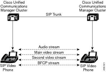
The following network diagram displays the network topology that is used for BFCP. The Cisco Unified Communications Manager clusters are involved only in forwarding SIP messages between the devices. After the endpoints negotiate BFCP, the BFCP stream itself is a point-to-point stream between the devices.
The following figure provides an example of a BFCP-capable network. The network is fully SIP capable. The Cisco Unified Communications Manager cluster sits in the middle and relays SIP signaling between the endpoints. The BFCP stream as well as the audio and video streams, are point-to-point between the endpoints.
BFCP Configuration Tips
To enable BFCP in Cisco Unified Communications Manager, check the Allow Presentation Sharing using BFCP check box in the SIP Profile Configuration window. If the check box is unchecked, all BFCP offers will be rejected. By default, the check box is unchecked.
BFCP is supported only on full SIP networks. For presentation sharing to work, BFCP must be enabled for all SIP endpoints as well as all SIP lines and SIP trunks between the endpoints.
The following figure provides an example of a complex video network with multiple Cisco Unified Communications Manager clusters. BFCP must be enabled on all the trunks and lines connecting the devices. For this network, BFCP must be enabled on the four SIP trunks and two SIP lines that connect the endpoints.

BFCP Limitations
Cisco Unified Communications Manager rejects the BFCP stream in the following scenarios:
-
The Allow Presentation Sharing using BFCP check box on the SIP Profile page is unchecked for one of the SIP lines or trunks in the network.
-
One endpoint offers BFCP, but the other does not.
-
The SIP line or SIP trunk uses MTP, RSVP, Trusted Relay Point (TRP), or Transcoder. In these cases, BFCP is not supported.
NoteBFCP is supported in Cisco Unified CM Release 8.6 as long as the call does not require MTP. For Cisco Unified CM Release 9.0 or later BFCP in MTP call is supported if the MTP is allocated from IOS routers that run 15.2.(2) T.
-
BFCP is supported only for SIP endpoints.
Note | BFCP is not supported when used between Cisco Unified Communications Manager and Cisco TelePresence MCU. |
Supported Features with BFCP
The following table highlights how some of the common features are handled while a BFCP presentation is ongoing:
Mid-call Feature |
Support |
|---|---|
Hold and Resume |
The Hold and Resume feature is fully supported when using a BFCP-capable endpoint, whether the endpoint is currently in a BFCP presentation or not. However, the user may have to reenable the presentation following the Resume operation. |
Transfer |
The Transfer feature is fully supported when using a BFCP-capable endpoint, whether the endpoint is currently in a BFCP presentation or not. However, the user may have to reenable the Presentation following the Transfer operation. |
Conference (non-BFCP conference controller) |
BFCP media line and presentation video are not supported when a BFCP-capable conference controller is used. However, the main video streams are supported. If two BFCP-capable endpoints enter into a conference with a non-BFCP conference controller, the main video is enabled throughout the conference, but the BFCP media and presentation video are disabled. |
Bandwidth Management
Bandwidth allocations for audio and video calls are managed through regions and locations that you configure in Cisco Unified Communications Manager Administration.
The amount of bandwidth available for a specific call must be able to manage the combination of all media streams that are associated with the session, including voice, video, signaling, and any extra media, such as a BFCP presentation. Cisco Unified Communications Manager contains features able to manage bandwidth.
- Call Admission Control
- Session Level Bandwidth Modifiers
- Video Resolution Support for SIP Phones
- RSVP
- Alternate Routing
- DSCP Marking
- Flexible DSCP Marking and Video Promotion
- Service Parameters for Flexible DSCP Marking and Video Promotion
- Configure Flexible DSCP Marking and Video Promotion Service Parameters
Call Admission Control
Call admission control enables you to control the audio and video quality of calls over a wide-area (IP WAN) link by limiting the number of calls that are allowed on that link at the same time. For example, you can use call admission control to regulate the voice quality on a 56-kb/s frame relay line that connects your main campus and a remote site.
Call admission control verifies whether there is sufficient bandwidth available to complete a call. Call admission control can reject calls due to insufficient bandwidth.
In Cisco Unified Communications Manager, locations-based call admission control works in conjunction with regions to define the characteristics of a network link. Regions and locations work in the following manner:
-
Regions allow the bandwidth of video calls to be set. The audio limit on the region may result in filtering out codecs with higher bit rates. However, for video calls, the video limit constrains the quality (resolution and transmission rate) of the video. For more information about regions, see Regions.
-
Locations define the amount of total bandwidth available for all calls on that link. When a call is made on a link the regional value for that call must be subtracted from the total bandwidth allowed for that link. For more information about locations, see Locations.
For more information about call admission control, see Call Admission Control.
Session Level Bandwidth Modifiers
Cisco Unified Communications Manager provides location call admission control support for handling session level bandwidth modifiers. Session level bandwidth modifiers are communicated as part of the parameters in the SDP portion of the initial SIP signaling. These parameters indicate the maximum amount of bandwidth each endpoint will support for that type of call. These parameters are used, along with regions and locations settings, to set the bandwidth for each call.
During the initial call setup, both parties communicate to Cisco Unified Communications Manager their maximum allowed bandwidth for the call. Cisco Unified Communications Manager passes this communication to the other endpoint, but if the bandwidth that is specified by the endpoint is greater than the region setting, Cisco Unified Communications Manager replaces the value with the region bandwidth value.
Cisco Unified Communications Manager uses the following rules to determine the amount of bandwidth to allocate to a specific call:
When Cisco Unified Communications Manager receives an Offer or Answer from an endpoint, it checks whether there is a session level bandwidth modifier in the SDP:
If there is a session level bandwidth modifier, Cisco Unified Communications Manager retrieves the bandwidth value from the modifier. If there is more than one modifier type, it retrieves the modifier in the following order of preference: Transport Independent Application Specific (TIAS), Application Specific (AS), Conference Total (CT).
If there is no session level bandwidth modifier, Cisco Unified Communications Manager retrieves the bandwidth value from the sum of the media level bandwidth modifiers.
The allocated bandwidth is the maximum of what the two endpoints support up to the maximum value of the Region setting. The allocated bandwidth cannot exceed the region setting.
Cisco Unified Communications Manager uses the following logic when communicating with endpoints:
When generating an Answer, Early Offer or Re-Invite Offer to an endpoint that contains more than one session level bandwidth modifier type (TIAS, AS, CT), Cisco Unified Communications Manager uses the same bandwidth value for each.
When generating an answer, Cisco Unified Communications Manager uses the same session level bandwidth modifier type (TIAS, CT, AS) that was received in the initial offer
For backward compatibility with older versions of Tandberg endpoints (such as MXP 1700), Cisco Unified Communications Manager suppresses the Session Level Bandwidth Modifier when a video call is put on hold and music on hold (MOH) is inserted.
Video Resolution Support for SIP Phones
If the session level bandwidth is greater than 800Kb/s and the imageattr[640 x 480] line in the SDP exists, then VGA is used.
If the session level bandwidth is greater than 800Kb/s and the imageattr[640 x 480] line in the SDP does not exist, then w360p is used.
If the session level bandwidth is less than 800Kb/s but greater than 480 bits per second and the imageattr[640 x 480] line exists, then VGA 15 frames per second is used.
Note | If you currently have a Cisco IP Phone model 9951, 9971, or 8961 that supports w360p (640 x 360) video resolution and are upgrading to Cisco Unified Communications Manager release 8.5(1) or later, you may notice changes in the resolution of video calls. The w360p resolution was introduced at phone load 9.2(1). |
Phone A sends a SIP message with an imageattr line in the SDP.
Cisco Unified Communications Manager deletes the imageattr line in the SDP and then sends the modified SIP message to Phone B.
Phone B attempts to send video with the w360p resolution because there is no imageattr line in the SDP portion of the SIP header.
RSVP
RSVP supports SCCP and SIP video calls. Configure RSVP policy for call admission control by using the Location Configuration window in Cisco Unified Communications Manager Administration.
Alternate Routing
If an endpoint cannot obtain the bandwidth that it needs for a video call, a video call retries as an audio call for the default behavior. To use route/hunt lists or Automated Alternate Routing (AAR) groups to try different paths for such video calls, uncheck the Retry Video Call as Audio setting in the configuration settings for applicable gateways, trunks, and phones.
DSCP Marking
Differentiated Services Code Point (DSCP) packet marking, which is used to specify the class of service for each packet, includes the following characteristics:
Audio streams in audio-only calls default to EF.
Video streams and associated audio streams in desktop video calls default to AF41.
Video streams and associated audio streams in immersive video calls default to CS4.
You can change these defaults through the use of a service parameter. The following service parameter settings affect DSCP packet marking for media RTP streams:
Flexible DSCP Marking and Video Promotion
Devices and applications use Differentiated Services Code Point (DSCP) markings to indicate the Quality of Service (QoS) treatment of IP communications. For example, desktop video endpoints may use multimedia conferencing AF41 marking for video media streams, while high-definition video room systems may use real-time interactive CS4 marking. When an application sends and receives IP communications to and from the same type of application, the DSCP markings are symmetric, and the QoS treatments of the IP communications that each application sends and receives are the same. However, when an application sends and receives media to and from a different type of application, the DSCP markings may be asymmetric, and the QoS treatments of the IP communications that each application sends and receives may be inconsistent. For example, the QoS treatment of the video media stream that a video room system receives from a desktop video endpoint may be inadequate to support the expected quality of the video room system.
Devices and applications are subjected to Call Admission Control (CAC) to ensure that adequate bandwidth is available for the duration of established sessions. The bandwidth that is utilized by established sessions is updated as the sessions begin and end. Attempts to establish new sessions that would exceed the available bandwidth are blocked. The amount of bandwidth available may be tracked independently for devices and applications of different types. For example, independent tracking of bandwidth may be available for desktop video endpoints and high-definition video room systems to send and receive video media streams.
When devices and applications of the same type send and receive communications to and from each other, the same type of bandwidth deductions are made in each direction. However, when devices and applications of different types send and receive communications to and from each other, different types of bandwidth deductions must be made in each direction. Moreover, the bandwidth deductions are usually symmetric in amount, by design, to reflect the usual behavior of an IP network. As a result, when devices and applications of different types send and receive communications to and from each other, the total bandwidth deductions may be up to double the amount of network bandwidth that is actually utilized. This inconsistency in bandwidth accounting may cause attempts to establish new sessions to be blocked unnecessarily. For example, when a desktop video endpoint and a Cisco TelePresence immersive video endpoint are in a call, in Release 9.x Unified Communications Manager CAC design deducts the same amount of bandwidth in both the video bandwidth pool and in the immersive bandwidth pool, because these two video endpoints are marking DSCP differently and the media packets can potentially traverse in different queues. This behavior unnecessarily deducts double the bandwidth that is required and potentially blocks new video calls.
In Unified Communications Manager Release 10.0(1) and later releases, the system administrator can configure a Video Promotion policy that reconciles the inconsistency in bandwidth accounting in favor of the application that receives more favorable CAC and QoS treatment. For example, if a session between a desktop video endpoint and a high-definition video room system is reconciled in favor of the video room system, then the reconciliation is deemed a promotion for the desktop video endpoint.
When reconciliation is in effect between devices and applications of different types, bandwidth is deducted only for the type of application that is favored by reconciliation. If sufficient bandwidth is available for a session of this type to be admitted, the device or application of the type that is not favored by reconciliation is instructed to change the DSCP markings that it uses to those that are used by the device or application of the type that is favored by reconciliation.
For example, if a desktop video endpoint is promoted in a session with a high-definition video room system, bandwidth accounting takes place as if the desktop video endpoint were an application of the same type as the video room system. The desktop video endpoint is instructed to change its DSCP markings to those that are used by the video room system. The QoS treatment is consistent in both directions, bandwidth is deducted for a session between devices and applications of the same type as the video room system, and bandwidth is not deducted for a session between devices and applications of the same type as the desktop video endpoint.
To activate the Flexible DSCP Marking and Video Promotion feature, in the Service Parameter Configuration window set the Use Video BandwidthPool for Immersive Video Calls service parameter to False and set the Video Call QoS Marking Policy service parameter to Promote to Immersive. When the Flexible DSCP Marking and Video Promotion feature is activated, Unified Communications Manager dynamically signals desktop video devices a Traffic Class Label that is indicative of the DSCP marking for each negotiated media stream.
Traffic Class Label
The Flexible DSCP and Video Promotion feature uses the Traffic Class Label (TCL) to instruct the SIP endpoint dynamically to mark its DSCP on a per call basis, based on the Video Promotion policy that is defined by the system administrator. Because TCL is a SIP Session Description Protocol (SDP) attribute that is defined per media line, the TCL and its associated DSCP markings can be different for the audio media line and the video media line of a video call. The system administrator can choose different DSCP markings for the audio stream and the video stream of the video call.
Interactions and Restrictions
The following interactions and restrictions apply to the Flexible DSCP Marking and Video Promotion feature:
The Flexible DSCP Marking and Video Promotion feature is supported over SIP intercluster trunks.
The Flexible DSCP Marking and Video Promotion feature is not supported over H.323 trunks and Media Gateway Control Protocol (MGCP) gateways.
The Flexible DSCP Marking and Video Promotion feature is supported for Skinny Client Control Protocol (SCCP) devices.
The Flexible DSCP Marking and Video Promotion feature is dependent on desktop SIP video endpoint support. At the time of the initial release of Unified Communications Manager Release 10.0(1), only Cisco DX650 series SIP phones provide the required endpoint support.
If pass-through MTPs are inserted in a call, Unified Communications Manager signals the MTP to mark the packets with the DSCP marking that is expected from the endpoint device that originally emitted the packet for the video stream. If the two endpoints on a call use different DSCP markings (for example, a Cisco TelePresence immersive video endpoint and a desktop video endpoint without Video Promotion), the MTPs preserve the DSCP marking in each stream direction.
Cisco recommends that you do not use the Flexible DSCP Marking and Video Promotion feature with Multilevel Precedence and Preemption (MLPP) service calls. When you need MLPP service functionality, Cisco recommends that you set the Video Call QoS Marking Policy and Use Video BandwidthPool for Immersive Video Calls service parameters to their default values. With default values for the Video Call QoS Marking Policy and Use Video BandwidthPool for Immersive Video Calls service parameters, Unified Communications Manager and endpoints use MLPP DSCP markings for the media packets.
Service Parameters for Flexible DSCP Marking and Video Promotion
Unified Communications Manager Release 10.0(1), and later releases, provides the following clusterwide service parameters to configure the Flexible DSCP Marking and Video Promotion feature:
Video Call QoS Marking Policy. This parameter allows the administrator to configure a Promote to Immersive policy that reconciles bandwidth allocation inconsistencies between a desktop video endpoint and a Cisco TelePresence immersive video endpoint in favor of the immersive endpoint. When promotion is performed, the audio and video bandwidth are reserved from the immersive bandwidth pool allocation. The policy of Promote to Immersive takes effect only for calls between an immersive video device and a desktop video device that supports flexible DSCP marking.
To configure a Promote to Immersive policy, in the Service Parameter Configuration window set the Use Video BandwidthPool for Immersive Video Calls parameter to False and set the Video Call QoS Marking Policy parameter to Promote to Immersive.
Use Video BandwidthPool for Immersive Video Calls. This parameter specifies whether Unified Communications Manager reserves bandwidth from the desktop video bandwidth pool for immersive video calls.
DSCP for Video Calls. This parameter specifies the DSCP value for the video stream of video calls.
DSCP for Audio Portion of Video Calls. This parameter specifies the DSCP value for the audio stream of video calls.
DSCP for TelePresence Calls. This parameter specifies the DSCP value for the video stream of Cisco TelePresence video calls.
DSCP for Audio Portion of TelePresence Calls. This parameter specifies the DSCP value for the audio stream of Cisco TelePresence video calls.
Default Intraregion Max Immersive Video Call Bit Rate (Includes Audio). This parameter specifies the default maximum total bit rate for each immersive video call within a particular region, when the Use System Default option is selected as the Max Immersive Video Call Bit Rate in the Region Configuration window for the relationship of the region with itself. For more information about choosing the options in the Region Configuration window, see the Cisco Unified Communications Manager Administration Guide.
Default Interregion Max Immersive Video Call Bit Rate (Includes Audio). This parameter specifies the default maximum total bit rate for each immersive video call between a particular region and another region, when the Use System Default option is selected as the Max Immersive Video Call Bit Rate in the Region Configuration window for the relationship of the region with the other region. For more information about choosing the options in the Region Configuration window, see the Cisco Unified Communications Manager Administration Guide.
Configure Flexible DSCP Marking and Video Promotion Service Parameters
To configure the Flexible DSCP Marking and Video Promotion service parameters, perform the following procedure.
| Step 1 | In Cisco Unified Communications Manager Administration, choose . The Service Parameter Configuration window displays. | ||||||||||||
| Step 2 | From the Server drop-down list, choose the server where you want to configure the parameters. | ||||||||||||
| Step 3 | From the Service drop-down list, choose the Cisco CallManager (Active) service. If the service does not display as active, ensure that the service is activated in Cisco Unified Serviceability. | ||||||||||||
| Step 4 | To configure the parameters, scroll to the appropriate area of the Service Parameter Configuration window and update the parameter values.
| ||||||||||||
| Step 5 | Click Save. |
Phone Configuration for Video Calls
The following setting for video-enabled devices affects video calls:
-
Retry Video Call as Audio-By default, this check box remains checked. Thus, if an endpoint (phone, gateway, trunk) cannot obtain the bandwidth that it needs for a video call, call control retries the call as an audio call. This setting applies to the destination devices of video calls.
-
Video Capabilities Enabled/disabled-This drop-down list box turns video capabilities on and off.
Additional Configuration for Video Calls
The following configuration considerations also affect the ability to make video calls in Cisco Unified Communications Manager:
Trunk Interaction with H.323 Client
Trunk interaction with the H.323 Client for video calls functions identically to interaction functions for audio calls. See the Trunks and Gatekeepers in Cisco Unified Communications Manager.
Call Routing for Video Calls
Call routing for video calls functions identically to call routing for audio calls.
Gateway Timer Parameter
For some bonding calls through the H.323/H.320 gateway, the gateway requires a longer time to exchange the H.323 TCS message. If the time required is greater than the timer setting for several Cisco CallManager service parameters, Cisco Unified Communications Manager will drop the call.
If the default Cisco Unified Communications Manager gateway timer values appear to be too short, Cisco Unified Communications Manager drops the call before completion of the call connection. Cisco recommends increasing the following service parameter timers values to avoid call failure.
Conference Control for Video Conferencing
Cisco Unified Communications Manager supports the following conference controls capabilities:
-
Roster/Attendee List
-
Drop Participant
-
Terminate Conference
-
Show Conference Chairperson/Controller
-
Continuous Presence
Cisco Unified Communications Manager also supports the following video conference capabilities for Skinny Client Control Protocol phones:
-
Display controls for video conferences. The Skinny Client Control Protocol phones can choose to use the continuous presence or voice-activated mode to view the video conference. When a mode is chosen, a message gets sent to the bridge to indicate which mode to use on the video channel. Switching between modes does not require renegotiation of media.
-
Display participant information such as the user name in the video stream. The system can use the participant information for other conferencing features such as roster.
Video and Interoperability
Cisco Unified Communications Manager supports native or direct interoperability between Cisco video endpoints and 3rd party video endpoints such as Polycom. This means that Cisco Unified Communications Manager does not require a media gateway or conference bridge, such as Cisco Unified Video Conferencing (CUVC), for a simple point-to-point call between the supported endpoints.
- Protocols and Deployments
- Cisco and Third-Party Endpoints Supported
- Limitations
- Internet Protocol Version 6 (IPv6)
Protocols and Deployments
Video and interoperability support the following protocols:
-
SIP to SIP
-
H323 to H323
-
SIP to SIP Intercluster trunk (ICT) to SIP
-
H323 to H323 ICT to H323
-
SIP to H323 with or without ICT
For more information about limitations and special considerations of this features, see the Limitations.
Video and interoperability support the following deployments:
-
High-Definition interoperability for point-to-point calls
-
Locations-based call admission control (CAC) only
-
Presentation sharing and secure interop between TelePresence and third-party endpoints that support the Telepresence Interop Protocol (TIP)
-
Multipoint calls involving Cisco TelePresence System (CTS), Cisco Unified Communications Manager, and third-party endpoints use Media transcoding Engine (MXE) and Cisco Unified Video Conferencing (CUVA)
Cisco and Third-Party Endpoints Supported
Video and interoperability support the following endpoints:
-
Cisco-certified third-party video endpoints
-
Cisco E20 (Tandberg E20)
-
Cisco Unified Clients Services Framework (CSF) based clients, such as Cisco Unified Communication interface for Microsoft Office Communicator (CUCiMOC) or CUCiConnect (for example, Cisco WebEx)
-
Cisco Unified Video Advantage (CUVA)
-
Cisco Unified Personal Communicator (CUPC)
-
MeetingPlace Conference bridges, such as MP Hardware Media Switch (HMS) or Software Media Switch (SMS)
To find a Cisco-certified third-party device, visit the Cisco Developer Network and perform the following steps:
-
Sign in to the Cisco Developer Network (CDN) (if applicable)
-
From the CDN main window, click the Technology Partners tab.
-
Click the Partner Search tab.
-
In the search box, enter the name of a 3rd party company (within all technologies) (for example, Polycom).
-
When the 3rd party company information displays, click the applicable links for more information.
Third-party devices get configured in Cisco Unified Communications Manager Administration, Phone Configuration. For the list of supported device types and licensing requirements, see Third-Party SIP Endpoints.
Limitations
The following limitations apply:
-
Advanced presentation sharing and security interoperability is supported only between two TelePresence Interop Protocol (TIP) capable endpoints.
-
H239 presentation sharing and H235 security are supported only between two H323 endpoints.
-
For ensure optimal resolution between the two endpoints, the protocol on the endpoints and the trunk should be identical; for example, SIP point-to-point endpoints connected by a SIP trunk.
-
Locations-based CAC only for interoperability with TelePresence
-
Ad hoc and Meet-Me conferencing support CUVC and MeetingPlace software media servers. Because the conferencing bridges support SCCP and the endpoints support SIP or H323, resolution may be limited to standard definition.
-
Cisco Intercompany Media Engine (IME) is not supported between Cisco Unified Communications Manager endpoints and Telepresence.
Internet Protocol Version 6 (IPv6)
Cisco Unified Communications Manager supports the transmission of video and application media streams on SIP lines and SIP trunks in IPv6 mode as well as in dual stack mode. Cisco Unified Communications Manager also supports interworking with other Unified Communications Manager clusters and Video Communications Servers (VCS) over SIP lines and SIP trunks that have been configured to use IPv4 or IPv6.
Far End Camera Control Protocol Support
The Far End Camera Control (FECC) protocol allows you to control a remote camera. Within video calls, FECC allows the party at one end of the call to control the camera at the far end. This control can include panning the camera from one side to the other, tilting the camera, or zooming in and out. For video conferences that use multiple cameras, FECC can be used to switch from one camera to another.
Cisco Unified Communications Manager supports the FECC protocol for video endpoints that are FECC-capable. Cisco Unified Communications Manager supports FECC for SIP-SIP calls or H.323-H.323 calls, but does not support FECC for SIP-H.323 calls. To support FECC, Cisco Unified Communications Manager sets the application media channel through SIP or H.323 signaling. After the media channel is established, the individual endpoints can communicate the FECC signaling.
Note | If a Media Terminating Point (MTP) (version 15.2(2)T or later) is present in a SIP-SIP call, and there are five channels available for the call, then FECC can be enabled. |
Video On Hold
The Video on Hold feature is for video contact centres where customers calling into the video contact centre are able to watch a specific video after initial consultation with the agent at the contact centre. In this case, the agent selects the video stream that gets played to the customer while the customer is on hold.
The "Video on Hold Server" configuration allows a media content server to be provisioned under the existing "Media Resources" menu. The media content server can stream audio and video content when directed by Unified Communications Manager. The media content server is an external device that can store and stream audio and video content under Unified Communications Manager control using SIP as the signal protocol. The media content server is capable of providing hi-definition video content at 1080p, 720p, or lower resolutions such as 360p.
In addition to the video contact centre, Video on Hold can be deployed within any enterprise if the deployment requires a generic video on hold capability. The configured Default Video Content Identifier for the Video on Hold server is used to play the video stream to the user on hold.
The media content server configuration and allocation for a particular session follows the "Media Resource Group" and "Media Resource Group List" constructs in Unified Communications Manager.
Cisco MediaSense is used as the media content server.
Note | In a Unified Contact Center with Customer Voice Portal (CVP) post routed deployment, you must allocate Video on Hold resources in the SIP trunk that runs between Unified Communications Manager and CVP, to get Video on Hold functionality. |
Interaction with Enhanced Location Call Admission Control
For this feature, the Cisco MediaSense servers can be collocated in a Unified Communications Manager cluster (the Cisco MediaSense cluster is directly connected to the cluster where the holding party is registered). In that case, the Unified Communications Manager cluster is responsible for deducting the bandwidth between the location of the party on hold and the Cisco MediaSense location. Since Video on Hold interactions make use of 720p or 1080p video streams, it is important to take the bandwidth usage into account before allowing new sessions - in order to maintain video quality of existing sessions.
Video on Hold Setup
Configure Unified Communications Manager with a SIP trunk to a Cisco MediaSense cluster. The SIP trunk to the Cisco MediaSense server will have the IP addresses of the Cisco MediaSense nodes configured. The Unified Communications Manager SIP trunk supports up to 16 destination IP addresses.
Note | Cisco MediaSense cluster should have two or more nodes for redundancy and scalability purposes. |
-
Cisco MediaSense is directly connected with the holding party's Unified Communications Manager cluster.
When Video on Hold server is located on the same cluster as the Holding Party, the SIP Trunk on the Video on Hold server configuration should point to the Cisco MediaSense server and the default content identifier should point to a stream ID that exists on the MediaSense server. The content identifier can be any alphanumeric string. No additional configuration is needed.
-
Cisco MediaSenseis centrally deployed with Session Management Edition (SME).
When Video on Hold server is located off the SME, the Video on Hold Server must be configured on the leaf cluster hosting the Holding Party. The SIP trunk on this Video on Hold Server should point to the SME SIP trunk. On the SME, a SIP Trunk should be provisioned to point to the Cisco MediaSense server.
There are three ways on how Unified Communications Manager can be configured to support this centralized deployment:
-
Content Identifier is numeric: In this case, a route pattern must be provisioned on the SME to route the INVITE to Cisco MediaSense server. Essentially, we use the left hand side of the INVITE URI sent by the leaf cluster to route the call to Cisco MediaSense server. The right hand side of the INVITE URI contains the IP address of SME node.
-
Content Identifier is alpha-numeric and contains the IP address of Cisco MediaSense: In this case, the content identifier configured on the leaf cluster should contain both the stream-id and the IP address of the Cisco MediaSense server (stream-id@mediasense-ipaddress).
On the SME cluster, a SIP route pattern must be configured that uses the IP address routing with the IP address of the MediaSense server matching the default content identifier. In this scenario, the route is based on the right hand side of the INVITE URI (IP address of MediaSense server) sent by the leaf cluster.
-
Content Identifier is alpha-numeric and contains the domain name: In this case, the content identifier configured on the leaf cluster should contain both the stream-id and the domain name of the Cisco MediaSense server (stream-id@cisco.com).
On the SME cluster, a URI catalog must be created with a SIP route pattern as a Route String. The content identifiers from the Cisco MediaSense server must be imported into this catalog using the URI infrastructure.
Note
The SIP Route Pattern must be configured to use domain routing. This SIP Route pattern should point to a SIP Trunk to Cisco MediaSense server.
-
Video on Hold SIP Trunk
The SIP Trunk pointing to Video on Hold server should be configured with default configuration. The following information is needed for configuring the SIP Trunk:
-
Name
-
Description
-
Device Pool
-
Location
-
Destination address and destination port (multiple IP addresses and ports can be specified)
-
SIP Trunk Security Profile
-
SIP Profile – A SIP profile with the option ping configured should be selected. If none exists, one should be created. This is not mandatory but will improve the user experience.
Note | Other configurations on the SIP Trunk are not supported for Video on Hold. |
Set Up Video On Hold
| Step 1 | In Cisco Unified Communications Manager Administration, choose . |
| Step 2 | Click Add New to set up a new Video on Hold server. |
| Step 3 | Enter the name of the Video on Hold server. |
| Step 4 | Enter a description for the server. |
| Step 5 | Enter the Default Video Content Identifier. |
| Step 6 | Select the SIP Trunk to be used from the drop-down list. If a new SIP Trunk needs to be created, click the button Create SIP Trunk. |
| Step 7 | Click Save. |
Video Telephony and Cisco Unified Serviceability
Cisco Unified Serviceability tracks video calls and conferences by updating performance monitoring counters, video bridge counters, and call detail records (CDRs).
Performance Monitoring Counters
Video telephony events cause updates to the following Cisco Unified Serviceability performance monitoring counters:
See the Cisco Unified Serviceability Administration Guide for details.
Video Bridge Counters
Video conference events cause updates to these Cisco video conference bridge performance monitoring counters:
-
ConferencesActive
-
ConferencesAvailable
-
ConferencesCompleted
-
ConferencesTotal
-
OutOfConferences
-
OutOfResources
-
ResourceActive
-
ResourceAvailable
-
ResourceTotal
These counters also display in the Cisco Unified Communications Manager object with the VCB prefix.
Call Detail Records
Video telephony events cause updates to Call Detail Records (CDRs) in Cisco Unified Serviceability. These CDRs include the following information:
-
IP address and port for video channels
-
Codec: H.261, H.263, H.264, Cisco VT Camera wideband video
-
Call bandwidth
-
Resolution: QCIF, CIF, SQCIF, 4CIF, 16CIF, or Custom Picture Format
Cisco Unified Communications Manager also stores CDRs for midcall video and supports the following call scenarios:
-
Skinny Client Control Protocol to Skinny Client Control Protocol calls
-
Skinny Client Control Protocol to Skinny Client Control Protocol calls across an intercluster trunk (ICT)
Note
CDR gets added when video is added mid-call, but CDR entry does not get removed as part of midcall video removal (for example, Cisco Video Telephony Advantage gets turned off).
 Feedback