Cisco Unified Communications Manager System Guide, Release 10.0(1)
Bias-Free Language
The documentation set for this product strives to use bias-free language. For the purposes of this documentation set, bias-free is defined as language that does not imply discrimination based on age, disability, gender, racial identity, ethnic identity, sexual orientation, socioeconomic status, and intersectionality. Exceptions may be present in the documentation due to language that is hardcoded in the user interfaces of the product software, language used based on RFP documentation, or language that is used by a referenced third-party product. Learn more about how Cisco is using Inclusive Language.
- Updated:
- August 28, 2014
Chapter: Resource Reservation Protocol
Contents
- Resource Reservation Protocol
- Configure RSVP
- RSVP Overview
- Advantages of RSVP
- RSVP Capabilities
- RSVP-Based MLPP
- Additional Features
- RSVP Caveats
- RSVP Agent and Quality of Service
- RSVP Agent Allocation
- RSVP Agent Interaction with Location-Based CAC
- RSVP Configuration
- Configure Clusterwide Default RSVP Policy
- Configure Location-Pair RSVP Policy
- Configure RSVP Retry
- Configure Midcall RSVP Error Handling
- Configure MLPP-to-RSVP Priority Mapping
- TSpec
- Audio TSpec
- Video TSpec
- DSCP
- Application ID
- RSVP for Media Devices
- Use RSVP Between Clusters
- Enable RSVP for a Call
- Special Configuration with RSVP
- Migrate to RSVP
- RSVP Interactions
- RSVP and IPv6
- RSVP and Shared-Line Calls
- RSVP and Music On Hold
- RSVP and Call Transfer
- RSVP and MLPP
- Troubleshooting RSVP
- Performance Monitoring Counters
- Call Detail Records
- Alarms
- Trace Information
- Troubleshooting End-to-End RSVP
Resource Reservation Protocol
Resource Reservation Protocol (RSVP) specifies a resource-reservation, transport-level protocol for reserving resources in IP networks. RSVP provides an additional method to achieve call admission control (CAC) besides location-based CAC. Location-based CAC constitutes a point-to-point CAC mechanism that does not take into account topology changes nor multi-tiered topologies, whereas RSVP does take these into account.
-
The following factors call for RSVP support as an alternative call admission control (CAC) mechanism in Cisco Unified Communications Manager:
-
Many customers request a full-mesh network topology for their video conferencing and video telephony environment to match their existing topology. If Cisco Unified Communications Manager does not support an RSVP-based CAC mechanism, a location-based CAC mechanism can still be leveraged as a viable solution.
-
The Quality of Service (QoS) baseline recommends that all VoIP and videoconferencing devices provide admission control by using RSVP.
For more information on call admission control (CAC), see the Call Admission Control.
This section provides an overview of RSVP, describes RSVP configuration within Cisco Unified Communications Manager, discusses migration to RSVP, shows example RSVP interactions, and provides troubleshooting information.
- Configure RSVP
- RSVP Overview
- RSVP Agent and Quality of Service
- RSVP Configuration
- Migrate to RSVP
- RSVP Interactions
- Troubleshooting RSVP
Configure RSVP
Resource Reservation Protocol (RSVP) specifies a resource-reservation, transport-level protocol for reserving resources in IP networks. RSVP provides an additional method to achieve call admission control (CAC) besides location-based CAC. Location-based CAC constitutes a point-to-point CAC mechanism that does not take into account topology changes nor multi-tiered topologies, whereas RSVP does take these into account.
RSVP Overview
RSVP includes the following features:
RSVP reservations get made for a particular session. A session comprises a flow that has a particular destination address, destination port, and a protocol identifier (TCP or UDP). RSVP reservations treat each session as one independent unit.
RSVP messages travel along the same path as the media flow path.
RSVP specifies a unidirectional protocol, so flows get reserved in only one direction.
RSVP specifies a receiver-oriented protocol; as such, the receiver of the stream requests the reservation.
RSVP supports both unicast and multicast environments.
RSVP messages flow transparently through non-RSVP routers and switches.
Advantages of RSVP
The following factors make RSVP a more desirable solution than location-based call admission control (CAC) for providing quality of service (QoS):
-
RSVP can handle complex topologies. Location-based CAC supports only hub-and-spoke or point-to-point topologies, such as simple Multiprotocol Label Switching (MPLS) any-to-any topologies. Locations cannot properly support multi-tiered topologies. Location-based CAC does not handle complex topologies, such as the following
-
RSVP exhibits network awareness, whereas location-based CAC cannot handle dynamic changes to bandwidth.
-
IP videoconferencing not only requires significant bandwidth but also requires specialized service from the network with respect to latency and packet loss. RSVP enables network to accommodate such traffic without unduly degrading the performance of other applications in the network
-
RSVP supports Multilevel Precedence and Preemption (MLPP) inherently.
RSVP Capabilities
The following capabilities get built on top of RSVP:
RSVP supports all signaling protocols, including SIP, SCCP, MGCP, and H.323.
RSVP works by enforcing a location-pair-based RSVP policy. You can enable and disable RSVP based on location pairs. This practice allows for migration.
The setting of a systemwide service parameter determines RSVP policy for the system. Therefore, you can enable or disable RSVP throughout the system. Location-pair-based policies, however, override the systemwide policy.
RSVP provides the following RSVP policy levels:
RSVP contains a retry reservation capability. This capability allows a call to gain or regain premium Quality of Service (QoS) even if the resources (bandwidth) are not currently available.
The RSVP Retry Timer controls the frequency of retry. The Mandatory RSVP Midcall Retry Counter and Mandatory RSVP mid call error handle option service parameters control the number of attempts to restore premium service by reserving the necessary resources if the initial RSVP policy specifies Mandatory.
RSVP integrates with Differentiated Services (DiffServ) QoS. The outcome of an RSVP reservation updates the Differentiated Services Code Point (DSCP) value.
The midcall failure policy that RSVP has means that this capability allows a user to determine what happens to the call if the call loses the bandwidth reservation in mid call. The following options exist:
RSVP supports bandwidth reservation for both audio and video streams.
RSVP provides application ID support.
RSVP supports Multilevel Precedence and Preemption (MLPP).
RSVP retains the reservation when a party gets put on hold. The reserved resource(s) can potentially get reused when the call resumes.
Shared-line devices that are located in the same location/region share the same reservation for incoming calls.
RSVP works with all Cisco Unified Communications Manager supplementary services and features to ensure that bandwidth reservation is correct after the service or feature is invoked. Examples of supported features include Call Transfer, Conference, and Call Forwarding.
RSVP supports Music on Hold (MOH) and annunciator features.
RSVP-Based MLPP
When RSVP is configured, MLPP functions as follows:
Cisco Unified Communications Manager passes the precedence level of the MLPP call to the RSVP agent by means of SCCP Quality of Service (QoS) messages.
Agents add priority information to RSVP requests.
IOS routers can use this priority information to admit calls.
If preemption occurs at the IOS router, the RSVP agent notifies Cisco Unified Communications Manager about the reservation failure due to preemption.
Cisco Unified Communications Manager notifies the preempted calling party and called party of the preemption. Cisco Unified Communications Manager uses the existing MLPP functionality, which resembles the location-based call admission control (CAC) MLPP preemption mechanism.
Preempted calls can either fail or continue with decreased QoS. Preempted calls receive the same treatment as midcall reservation failure.
Additional Features
Cisco Unified Communications Manager supports the following interactions:
RSVP agent supports Differentiated Services Control Point (DSCP) remarking. This capability mitigates the trust issues with desktop applications, such as Communicator and VTA.
RSVP supports audio, video, and data pass-through. Video data pass-through allows video and data packets to flow through RSVP agent and media termination point devices. Video data pass-through also allows audio transcoding to work with video calls. Audio pass-through allows encrypted calls to flow through MTPs.
Pass-Through Conditions
The following conditions apply to both audio and video/data pass-through:
All intermediate MTP devices support pass-through.
No "MTP required" check box is checked for either endpoint.
The following additional audio pass-through condition applies:
The following additional video pass-through condition applies:
RSVP Caveats
RSVP presents the following support limitations:
-
Cisco Unified Communications Manager does not support RSVP interaction with endpoints that support RSVP natively.
-
RSVP does not support the G. Clear Codec.
 Note | RSVP does not conflict with Automated Alternate Routing (AAR), which continues to function if AAR is configured. See the Automated Alternate Routing for details. |
RSVP Agent and Quality of Service
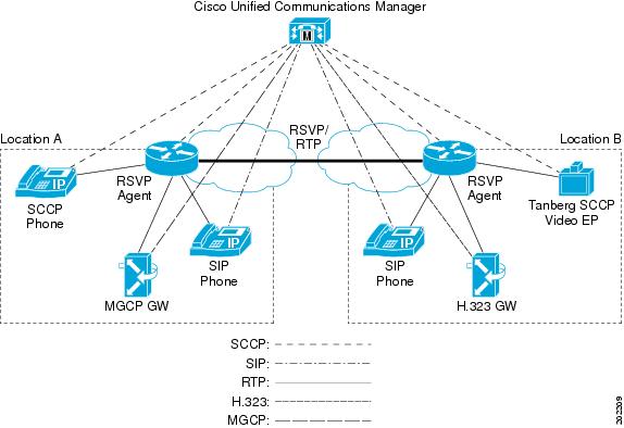
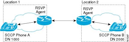
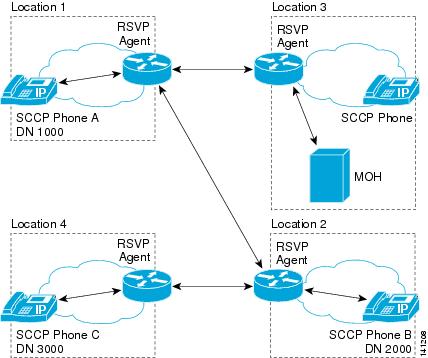
Cisco Unified Communications Manager uses an RSVP agent, which is an IOS-based RSVP proxy with an SCCP interface to support RSVP. Cisco Unified Communications Manager communicates with the RSVP agent through a set of SCCP messages. The RSVP agent registers with Cisco Unified Communications Manager as either a media termination point or a transcoder device.
Each endpoint requires an RSVP agent. The agent pair (one agent for endpoint A, another agent for endpoint B) signals RSVP on behalf of the endpoints that Cisco Unified Communications Manager controls.
RSVP Agent Example
RSVP Agent Allocation
Cisco Unified Communications Manager allocates the RSVP agent resource in the same manner that it allocates media termination point and transcoder resources. You configure a Media Resource Group List (MRGL) that includes the RSVP agent and assign the MRGL to the device or the device pool that associates with the device. RSVP reservation fails if the same RSVP agent is assigned to both endpoints that are making a call.
RSVP Agent Interaction with Location-Based CAC
Cisco recommends that you do not activate both location-based Call Admission Control (CAC) and RSVP at the same time, except during the migration period from location-based CAC to RSVP.
If location bandwidth is not set to unlimited (infinite bandwidth) in the location, Cisco Unified Communications Manager performs location-based CAC before performing RSVP. If location-based CAC fails, the call fails, and Cisco Unified Communications Manager does not invoke RSVP.
If location bandwidth is set to unlimited (infinite bandwidth) in the location, Cisco Unified Communications Manager invokes RSVP based on RSVP policy for the location pair that is associated with the calling and the called parties.
RSVP Configuration
RSVP configuration comprises configuration of various service parameters and other components. The sections that follow describe the various service parameters and other configuration that is needed to configure RSVP.
 Tip | Before you configure RSVP, see the Configure RSVP. |
- Configure Clusterwide Default RSVP Policy
- Configure Location-Pair RSVP Policy
- Configure RSVP Retry
- Configure Midcall RSVP Error Handling
- Configure MLPP-to-RSVP Priority Mapping
- TSpec
- DSCP
- Application ID
- RSVP for Media Devices
- Use RSVP Between Clusters
- Enable RSVP for a Call
- Special Configuration with RSVP
Configure Clusterwide Default RSVP Policy
To configure the clusterwide RSVP policy, configure the following clusterwide (System - RSVP) service parameter for the Cisco CallManager service:
Configure Location-Pair RSVP Policy
Use the Location Configuration window to configure the RSVP policy for a given location pair. The RSVP policy that is configured for a location pair overrides the default interlocation RSVP policy that you configure in the Service Parameter Configuration window.
To configure the RSVP policy for a pair of locations, configure the RSVP Setting field for the location pair:
| Step 1 | In Cisco Unified Communications Manager Administration, choose the menu option. |
| Step 2 | Find one location of the location pair and select this location. |
| Step 3 | To modify the RSVP policy between the selected location and another location, select the other location in the location pair. |
| Step 4 | In the RSVP Setting drop-down list box, choose an RSVP policy for
this location pair.
You can set this field to the following values:
|
Configure RSVP Retry
Use the following clusterwide (System - RSVP) service parameters to configure the frequency and number of RSVP retries:
To locate and configure these service parameters, follow these steps:
Configure Midcall RSVP Error Handling
Use the following clusterwide (System - RSVP) service parameter to configure midcall RSVP error handling:
To locate and configure this service parameter, follow these steps:
Configure MLPP-to-RSVP Priority Mapping
Use the following clusterwide (System - RSVP) service parameters to configure the mapping from a caller MLPP precedence level to RSVP priority:
-
MLPP EXECUTIVE OVERRIDE To RSVP Priority Mapping
- MLPP FLASH OVERRIDE To RSVP Priority Mapping
- MLPP FLASH To RSVP Priority Mapping
- MLPP IMMEDIATE To RSVP Priority Mapping
- MLPP PL PRIORITY To RSVP Priority Mapping
- MLPP PL ROUTINE To RSVP Priority Mapping
To locate and configure these service parameters, follow these steps:
TSpec
The TSpec object describes the traffic that the sender generates. The TSpec gets transported through the network to all intermediary routers and to the destination endpoint. The intermediate routers do not change this object and the object gets delivered unchanged to the ultimate receiver(s).
Audio TSpec
For audio flows, the TSpec calculations specify the following measurements:
-
burstSize (bytes)-This value gets calculated as the size of the packet times the number of packets in a burst. For audio flows, the burst usually specifies 1 to 2.
-
peakRate (bytes)-The peakRate, in bytes, refers to the maximum bytes/second that the endpoint transmits at any given time. If the burst is small, as is the case in audio streams, the peakRate can be calculated as 1.1 (or 1.2) times the tokenRate.
To avoid adjusting the bandwidth reservation upward when the call gets answered, Cisco Unified Communications Manager reserves the maximum bandwidth for each region codec at call setup time. Cisco Unified Communications Manager then modifies or adjusts the bandwidth based on the media capability of the connected parties when the call gets answered.
Example Audio TSpec Calculations
See the following examples of bandwidth calculations for different region codecs for call setup.
G.711: 8 sample/frame; for 10-ms packet: 80 + 40 (header) = 120 * 100 (packets/sec) = 12000 * 8 = 96 kb/s; (packet_size_in_ms*8+40)*8000/packet_size_in_ms
G.729: 10 ms/frame; 8 kb/s; Default is 20 ms; 0 and 10 are possible. For 10-ms packet: 10 + 40 = 50 * 100 = 5000 * 8 = 40 kb/s
kb/s: (packet_size_in_ms+40)*8000/packet_size_in_ms
The TSpec of the G.711 codec specifies the following calculations:
Tspec.mAverageBitRate = bwPlusHeader = 96 kb/s;
Tspec.mPeakRate = Tspec.mAverageBitRate * (1.2) = 115;
Tspec.mBurstSize = PacketSize * 2 = 120 * 2 = 240;
Video TSpec
For video streams, the packet length does not depend on codecs. Individual implementations provide the basis for packet length. Also, the packet sizes do not remain uniform across all packets. Estimating the number of packets per second therefore proves difficult.
Assume that the maximum packet size for a video stream specifies 1000 bytes.
The RSVP Video Tspec Burst Size Factor service parameter in the Clusterwide Parameters (System - RSVP) section of the service parameters for the Cisco CallManager service allows you to configure the video stream burst size. The default value for this service parameter specifies 5.
The following elements comprise the video Tspec:
-
burstSize (bytes)-Burst size factor (5) * max packet size (1000)
-
peakRate (bytes)-This element refers to the maximum bytes/second that the endpoint transmits at any given time. If the burst is small, as is the case with audio streams, you can calculate the peakRate as 1.1 (or 1.2) times the tokenRate.
Cisco Unified Communications Manager attempts to use the bandwidth for the entire video call to reserve bandwidth for the video stream first: 384 kb + overhead.
If insufficient bandwidth exists for the entire video call, Cisco Unified Communications Manager next attempts to reserve the following amount of bandwidth: (video call bandwidth - audio stream codec) + overhead).
Example: (384 - 64) + 22 = 342 kb/s
The Tspec for the 384 kb codec specifies the following calculations:
Tspec.mAverageBitRate = bwPlusHeader = 410 kb/s;
Tspec.mPeakRate = Tspec.mAverageBitRate = 410;Tspec.mBurstSize = 1000 * 5 = 5000;
DSCP
If the RSVP reservation fails, Cisco Unified Communications Manager instructs the RSVP agent or endpoint devices (in case a failure to allocate an RSVP agent occurs) to change media Differentiated Services Control Point (DSCP) marking to best effort. Otherwise, an excess of EF-marked media packets can degrade quality of service (QoS) even for flows that have a reservation.
Cisco Unified Communications Manager uses the clusterwide (System - QoS) DSCP for Audio Calls When RSVP Fails service parameter or the DSCP for Video Calls When RSVP Fails service parameter to determine the DSCP values for this instruction when RSVP fails for the call.
Application ID
An application ID specifies an RSVP object that can be inserted in a policy element in an RSVP message. RFC 2872 describes this object. This policy object serves to identify the application and associates the application with the RSVP reservation request, thus allowing routers along the path to make appropriate decisions based on the application information.
The following clusterwide (System - RSVP) system parameters allow configuration of application IDs:
When a voice call is made between locations with an RSVP policy, the resulting reservations for the audio stream get tagged with the RSVP Audio Application ID. When a video call is made between locations with an RSVP policy, the resulting reservations for the audio stream and the video stream get tagged with the RSVP Video Application ID.
If a call changes from audio to video, the following happens:
-
The existing audio reservation gets released from the audio pool.
-
The audio bandwidth reservation is re-attempted in the video pool with optional policy.
-
The Application ID for the audio stream gets changed to RSVP Video, and the new video stream gets tagged with the RSVP Video Application ID.
If a video call changes to an audio call, the following happens:
-
Both existing audio and video reservations are released from the video pool.
-
The audio bandwidth reservation is re-attempted in the audio pool with optional policy.
-
The Application ID for the audio stream gets changed to RSVP Audio.
Note | In an end-to-end RSVP environment, when the audio bandwidth reservation is re-attempted in either the audio or video pool, both clusters try to release the audio bandwidth from the existing pool and re-attempt the audio reservation in the new pool. This can cause a race condition that might take up to a re-try cycle to complete before the audio bandwidth reservation in the new pool happens. |
By using this call admission control model, you can reserve a certain amount of bandwidth for voice calls and allow them to use the entire available bandwidth in the priority queue, thus ensuring that all the available bandwidth can be used for voice calls if no video calls are in progress. If enough available bandwidth exists in the priority queue, calls can optionally be enabled for video. You can set limits on how much bandwidth the video-enabled calls can consume, but if voice calls are consuming all the available bandwidth, it might not be possible to place a video call at all.
RSVP for Media Devices
Because conference bridges, music on hold servers, and annunciators do not specify Media Resource Group List (MRGL) configuration, you make RSVP resources available for these devices by associating these devices with a device pool that has an associated RSVP agent. The MRGL that is associated with the device pool gets used to allocate RSVP resources for these types of media devices.
Use RSVP Between Clusters
RSVP supports reservations between end points in separate clusters by using two different configurations: local and end-to-end.
Local RSVP does not support reservations between two RSVP agents that are located in different clusters. It uses two RSVP agents per cluster, and does not use RSVP across the trunk that connects the clusters. This is the default configuration.
Consider the following scenario:
endpoint A - agentA - agentICT1 - ICT1 - ICT2 - agentICT2 - agentB - endpoint B
where A specifies an endpoint in cluster 1, B specifies an endpoint in cluster 2, ICT1 and ICT2 specify the intercluster trunks within clusters 1 and 2, and the RSVP Agents associate with the respective devices.
In this scenario, Cisco Unified Communications Manager 1 controls the reservation between agentA and agentICT1, and Cisco Unified Communications Manager 2 controls the reservation between agentB and agentICT2.
As an alternative, you can use Cisco Unified Border Element (formerly Cisco Multiservice IP-to-IP) gateways. See the Configure Gatekeepers and Trunks for more information.
End-to-end RSVP configuration is available if the clusters are connected by a SIP trunk. End-to-end RSVP uses RSVP on the entire connection between the end points, and uses only one RSVP agent per cluster.
Consider the following scenario:
endpoint A - agentA - ICT1 - ICT2 - agentB - endpoint B
where A specifies an endpoint in cluster 1, B specifies an endpoint in cluster 2, ICT1 and ICT2 specify the intercluster trunks within clusters 1 and 2, and the RSVP Agents associate with the respective end points.
In this scenario, Cisco Unified Communications Manager establishes an end-to-end RSVP connection between agentA and agentB.
Configuring End-to-End RSVP Over a SIP Trunk
RSVP configuration on a SIP trunk is determined by the SIP profile that is applied to the trunk. To enable end-to-end RSVP on a SIP trunk, configure the trunk’s SIP profile as follows:
Enable RSVP for a Call
Special Configuration with RSVP
In an RSVP session, special configuration applies if all the following conditions exist:
One endpoint device, such as Cisco IP Interactive Voice Response (IP IVR), was configured to support only the G.711 codec.
RSVP was configured for the call.
The interregion codec specifies G.729 between the calling RSVP agent and the called RSVP agent.
When the call is made, to achieve successful allocation and reservation of RSVP agent resources and bandwidth, the administrator must configure the media termination point (MTP)/RSVP agent with the G.729 codec in addition to the pass-through codec. This configuration allows insertion of a transcoder between the RSVP agent of the called side and the called device at the time of media connection. When codecs match, codec pass-through takes place; if codecs do not match, the call cannot continue without a transcoder.
If configuration of the G.729 codec in the agent does not take place, the call will fail because Cisco Unified Communications Manager will not invoke a transcoder that is needed for the RSVP call.
The situation arises if either of the following conditions apply: the interregion codec gets used between calling and called agents or between two endpoints that specify G.729. Two options exist to enable successful routing of this call:
Use RSVP agent for IVR as a transcoder. In this case, the interregion codec between the transcoder/RSVP agent and IVR needs to specify the G.711 codec.
Use software MTP as RSVP Agents and insert a transcoder between IVR and the RSVP agent for IVR. In this case, ensure the software MTP is configured with the G.729 codec in addition to the pass-through codec.
Keep in mind that the RSVP agent that has transcoding capability cannot perform G.729-to-G.729 transcoding. If you use a transcoder as an RSVP agent, you either must use the pass-through codec or configure the transcoder, so one of the codecs that is used on both sides of the transcoder specifies G.711.
Migrate to RSVP
Migration from location-based call admission control (CAC) to RSVP requires that you take some special circumstances into consideration. During the RSVP deployment time period, devices in some locations will probably have RSVP agent that is configured while others do not have RSVP agent that is configured.
When a call takes place from a location that has RSVP agent to another location that does not have RSVP agent, Cisco Unified Communications Manager will manage the quality of service (QoS) of the call by using both location-based CAC and RSVP. The first part of the call, from the location that has RSVP agent to the hub/central site that has RSVP, uses the RSVP mechanism. The second part of the call, from the hub/central site to the location that does not have RSVP, gets managed through location-based CAC. If either mechanism fails to allocate bandwidth, the call fails.
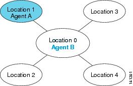
Location Pair
RSVP Policy
1
1
None
1
Not 1
Mandatory
Not 1
Not 1
None
Calls within locations 0, 2, 3, and 4 use the same CAC as before.
Calls within location 1 are not subject to CAC.
Calls between location 0 and location 1 use RSVP CAC.
Calls between location 1 and locations 2, 3, or 4 have RSVP on the
0-to-1 link and location-based CAC on the 0-to- 2, 0-to-3, or 0-to-4 link. If
either mechanism fails, the call fails.
Location
Bandwidth
0
Unlimited
1
Unlimited
2
1500
3
3000
4
3000
RSVP Interactions
The following sections provide examples of RSVP interaction with various Cisco Unified Communications Manager features and services.
RSVP and IPv6
RSVP does not support IPv6. RSVP calls support IPv4. If RSVP is required for the call and any device in the call is configured for or uses an IPv6 address, Cisco Unified Communications Manager rejects the call, and the caller receives a busy tone. For more information on IPv6, see RSVP and MLPP.
RSVP and Shared-Line Calls
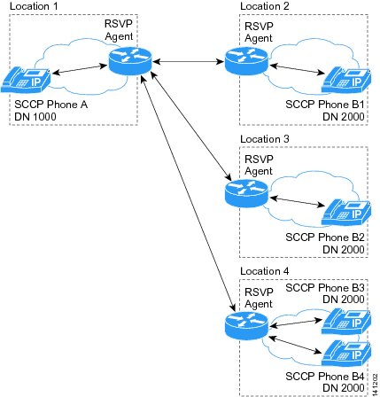
The example shows the following configuration during the alerting phase of the shared-line call:
-
Phones B1 (in location 2), B2 (in location 3), and B3 and B4 (both in location 4) share the DN 2000.
-
The RSVP agent in location 1 has a single reservation. The reservation has multiple destinations, one to each RSVP agent in the other locations (2, 3, and 4).
-
RSVP agent in location 4 has one allocated reservation. Phones B3 and B4 share this reservation.
Phones B3 and B4, which share the DN 2000, use a single RSVP agent.
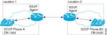
After phone B2 (in location 3) answers the shared-line call, the RSVP reservation between location 1 and location 2, as well as the reservation between location 1 and location 4, get torn down. Only the RSVP reservation between location 1 and location 3 remains established.
RSVP and Music On Hold
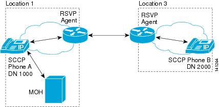
RSVP preserves the reservation between phone A and phone B while phone A is on hold and receiving Music On Hold. After the call between phone A and phone B resumes, the reserved resource gets reused. Because phone A and the MOH server that provides its music on hold are in the same location, no need exists for RSVP reservation between phone A and the MOH server.
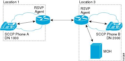
This example shows a phone call between phone A and phone B, with the music on hold server in the same location as phone B. If phone B puts phone A on hold, so phone A receives music on hold, the reservation that was used to connect phone A and phone B gets reused for the music on hold session. No additional reservation gets created.
If phone B puts phone A on hold, so phone A receives music on hold, RSVP agent preserves the reservation that was used to connect phone A and phone B. Another RSVP agent creates a new reservation between phone A and the MOH server.
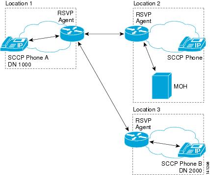
RSVP and Call Transfer
In the illustration, phone A, DN 1000, location 1, calls phone B, DN 2000, location 2. RSVP agent establishes a reservation for the call. Phone B presses the Transfer button and dials DN 3000. Phone C, DN 3000, location 4, answers the call.
When phone B initiates transfer of the call from phone A to phone C in this configuration, the RSVP agent preserves the reservation between phone A and phone B. An RSVP agent creates a new RSVP reservation between phone A and the MOH server. An RSVP agent creates a new reservation between phone B and phone C.
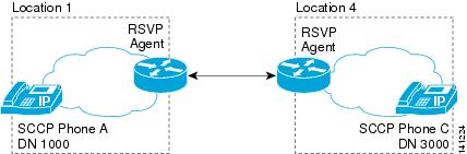
After phone B completes the transfer, a new RSVP reservation gets created between phone A and phone C. The RSVP reservations between phone A and the MOH server, phone A and phone B, and phone B and phone C, all get torn down.
RSVP and MLPP
The following sections discuss various RSVP-based MLPP scenarios.
Note | RSVP-based MLPP does not support nonpreemtable numbers. |
Scenario 1: A Lower Priority Call Gets Preempted During Congestion
Initial call RSVP Policy: Mandatory
Midcall RSVP Policy: Call fails. No retries
Other configuration details: RSVP bandwidth equals 100 kb/s. Each call takes 80 kb/s; therefore, only one call can obtain a reservation successfully.
Scenario 2: A Video Call Proceeds as an Audio-Only Call If Sufficient Bandwidth Does Not Exist
Initial call RSVP Policy: Mandatory with video desired
Midcall RSVP Policy: Best effort
Other configuration details: RSVP bandwidth equals 100 kb/s. Each audio calls takes 80 kb/s; therefore, only one call can obtain a reservation successfully.
Scenario 3: A Lower Priority Call Continues During Congestion with No Premium QoS
Initial call RSVP Policy: Optional
Midcall RSVP Policy: Best effort
Other configuration details: RSVP bandwidth equals 100 kb/s. Each audio calls takes 80 kb/s; therefore, only one call can obtain a reservation successfully.
Start a Priority call.
The call succeeds.
Start a Routine call.
The call succeeds, but no premium QoS is available. (The call uses a different DSCP.)
Start a Flash call.
The call succeeds. The QoS for the Priority call decreases.
End (hang up) the Flash call.
The Priority call recovers the RSVP reservation, and QoS increases.
Troubleshooting RSVP
For information about troubleshooting end-to-end RSVP, see the Troubleshooting End-to-End RSVP.
RSVP provides the performance monitoring (PerfMon) counters, Call Detail Records (CDRs), alarms, and trace information to assist with troubleshooting RSVP.
- Performance Monitoring Counters
- Call Detail Records
- Alarms
- Trace Information
- Troubleshooting End-to-End RSVP
Performance Monitoring Counters
The following Cisco Unified Communications Manager RSVP admission control performance monitoring counters exist:
RSVP AudioReservationErrorCounts
RSVP MandatoryConnectionsInProgress
RSVP OptionalConnectionsInProgress
RSVP TotalCallsFailed
RSVP VideoCallsFailed
RSVP VideoReservationErrorCounts
These location-based and node-based performance monitoring counters do not synchronize across nodes.
To troubleshoot RSVP agent resources, the following RSVP performance monitoring counters exist:
See the Cisco Unified Real Time Monitoring Tool Administration Guide for descriptions of the performance monitoring counters and instructions on how to view performance monitoring counters.
Call Detail Records
The Cisco Unified Communications Manager Quality of Service (QoS) RSVP agent feature adds the following Call Detail Record (CDR) fields:
-
origRSVPAudioStat-Status of RSVP audio reservation from originator to terminator
-
destRSVPAudioStat-Status of RSVP audio reservation from terminator to originator
-
origRSVPVideoStat-Status of RSVP video reservation from originator to terminator
-
destRSVPVideoStat-Status of RSVP video reservation from terminator to originator
These fields reflect the status of RSVP bandwidth reservation per audio or video stream.
The following values apply for the Cisco Unified Communications Manager RSVP CDR status fields:
-
0-Indicates RSVP NO RESERVATION condition, which is the default value.
-
1-Indicates RSVP RESERVATION FAILURE condition at call setup or feature invocation.
-
2-Indicates RSVP RESERVATION SUCCESS condition at call setup or feature invocation.
-
3-Indicates RSVP RESERVATION NO RESOURCE (RSVP agent) condition at call setup or feature invocation.
-
4-Indicates RSVP MID_CALL FAILURE_PREEMPTED condition (preempted after call setup).
-
5-Indicates RSVP MID_CALL FAILURE_LOST_BANDWIDTH condition (includes all midcall failure except MLPP preemption).
The Cisco Unified Communications Manager RSVP CDR status field value gets concatenated, and the most recent 32 status values get retained for the call.
Example
A call establishes with the Optional RSVP policy, and the initial RSVP reservation succeeds. The call subsequently loses its bandwidth reservation and regains the bandwidth reservation after retrying. This sequence repeats several times during the call, and the call ends with a successful RSVP reservation. In this case, the CDR shows the following string as the Cisco Unified Communications Manager RSVP reservation status for that particular stream:
"2:5:2:5:2:5:2" (success:lost_bw:success:lost_bw:success:lost_bw:success)
See the Cisco Unified Communications Manager CDR Analysis and Reporting Administration Guide for additional information.
Alarms
The RsvpNoMoreResourcesAvailable alarm gets generated when no RSVP agent resource is available.
The following Cisco Unified Communications Manager alarm catalog defines this alarm: /vob/ccm/Common/XML/AlarmCatalog/Communications Manager.xml.
Trace Information
RSVP generates several SDL and SDI traces for the Cisco CallManager service upon RSVP reservation failure. The user sees the RSVP error codes in both the Cisco Unified Communications Manager SDL and SDI trace files.
The RSVP agent can send the following RSVP Reservation error codes:
QOS_CAUSE_RESERVATION_TIMEOUT=0,
QOS_CAUSE_PATH_FAIL,
QOS_CAUSE_RESV_FAIL,
QOS_CAUSE_LISTEN_FAIL,
QOS_CAUSE_RESOURCE_UNAVAILABLE,
QOS_CAUSE_LISTEN_TIMEOUT,
QOS_CAUSE_RESV_RETRIES_FAIL,
QOS_CAUSE_PATH_RETRIES_FAIL,
QOS_CAUSE_RESV_PREEMPTION,
QOS_CAUSE_PATH_PREEMPTION,
QOS_CAUSE_RESV_MODIFY_FAIL,
QOS_CAUSE_PATH_MODIFY_FAIL
Troubleshooting End-to-End RSVP
This section provides troubleshooting information for end-to-end RSVP. For more information about end-to-end RSVP, see the Use RSVP Between Clusters.
|
Problem |
Recommended Action |
|---|---|
|
After a tandem/remote transfer, the final call is no longer an end-to-end RSVP call. |
In the transferring node, make sure that the RSVP policy is activated between locations to which the inbound and outbound SIP trunk is assigned. |
|
When the call is put on hold, there is no end-to-end RSVP between the MOH server and a held party. |
In the holding cluster, make sure that the MOH’s device pool has a MRGL that has the RSVP agents assigned. Also make sure RSVP policy is activated between locations to which the MOH server and SIP trunk are assigned. |
|
When a device in campus (Hub_none location) makes or receives a call, there is no end-to-end RSVP. |
Make sure that RSVP policy is activated between the Hub_none location and location to which the SIP trunk is assigned. |
|
When a conference call gets invoked, there is no end-to-end RSVP between the conference bridge and remote conference participants. |
In the cluster that invoked the conference call, make sure that the conference bridge’s device pool has a MRGL that has the RSVP agents assigned. Also make sure that RSVP policy is activated between locations to which the conference bridge and SIP trunks are assigned. |
|
When a call gets blind transferred to a remote system, there is no end-to-end RSVP between the announciator and the calling phone. |
In the transferring cluster, make sure that the annunciator’s device pool has a MRGL that has the RSVP agents assigned. Also make sure RSVP policy is activated between locations to which the annunciator and SIP trunks are assigned. |
|
A basic end-to-end RSVP call fails. |
Make sure that the RSVP policy has been activated between endpoint and trunk on both the clusters, and that the SIP profile for the inbound and outbound SIP trunk is configured to support end-to-end RSVP on both clusters. |
|
End-to-end RSVP reservation fails. |
A possible cause is that the same router is being used as the calling and called RSVP agents, and that router is not running the latest IOS version, which supports loopback on RSVP reservation. Make sure that the router is running the latest IOS version. |