Administration Guide for the Cisco Unified Application Environment, Release 8.5
Bias-Free Language
The documentation set for this product strives to use bias-free language. For the purposes of this documentation set, bias-free is defined as language that does not imply discrimination based on age, disability, gender, racial identity, ethnic identity, sexual orientation, socioeconomic status, and intersectionality. Exceptions may be present in the documentation due to language that is hardcoded in the user interfaces of the product software, language used based on RFP documentation, or language that is used by a referenced third-party product. Learn more about how Cisco is using Inclusive Language.
- Updated:
- December 15, 2010
Chapter: Configuring an Example Environment
- Setting Up an Example Deployment and Performing Configuration Tasks
- Task 1: Log in to the Cisco Unified Application Environment Administration
- Task 2: Create a Cisco Unified Media Engine Connection
- Task 3: Create a SIP Connection to Cisco Unified Communications Manager
- Task 4: Create a SIP Trunk
- Task 5: Set Up a Route Pattern
- Task 6: Create Phones in Cisco Unified Communications Manager
- Task 7: Configure Your Phone to Connect to the Cisco Unified Communications Server
- Task 8: Configure the SIP Provider Plugin
- Task 9: Install, Configure, and Test Sample Applications
Configuring an Example Environment
This appendix provides an example deployment scenario for setting up and configuring a Cisco Unified Application Environment.
The following section describes how to set up and configure an example environment having these properties:
•![]() One Cisco Unified Application Server and one Cisco Unified Media Engine co-located on the same physical server
One Cisco Unified Application Server and one Cisco Unified Media Engine co-located on the same physical server
•![]() SIP used for telephony integration
SIP used for telephony integration
•![]() One Cisco Unified Communications Manager cluster
One Cisco Unified Communications Manager cluster
•![]() Test phones
Test phones
•![]() Sample applications used for integration
Sample applications used for integration

Note ![]() Actual IP addresses will differ in your own test environment.
Actual IP addresses will differ in your own test environment.
The specific tasks required for setting up the Cisco Unified Application Environment will vary according to protocols and applications such as these:
•![]() Number of Cisco Unified Application Servers and Cisco Unified Media Engines
Number of Cisco Unified Application Servers and Cisco Unified Media Engines
•![]() Number of Cisco Unified Communications Manager clusters
Number of Cisco Unified Communications Manager clusters
•![]() Type of telephony protocol
Type of telephony protocol
•![]() Types of applications used
Types of applications used
Setting Up an Example Deployment and Performing Configuration Tasks
To set up your example deployment, you must perform these configuration tasks:
•![]() Task 1: Log in to the Cisco Unified Application Environment Administration
Task 1: Log in to the Cisco Unified Application Environment Administration
•![]() Task 2: Create a Cisco Unified Media Engine Connection
Task 2: Create a Cisco Unified Media Engine Connection
•![]() Task 3: Create a SIP Connection to Cisco Unified Communications Manager
Task 3: Create a SIP Connection to Cisco Unified Communications Manager
•![]() Task 5: Set Up a Route Pattern
Task 5: Set Up a Route Pattern
•![]() Task 6: Create Phones in Cisco Unified Communications Manager
Task 6: Create Phones in Cisco Unified Communications Manager
•![]() Task 7: Configure Your Phone to Connect to the Cisco Unified Communications Server
Task 7: Configure Your Phone to Connect to the Cisco Unified Communications Server
•![]() Task 8: Configure the SIP Provider Plugin
Task 8: Configure the SIP Provider Plugin
•![]() Task 9: Install, Configure, and Test Sample Applications
Task 9: Install, Configure, and Test Sample Applications
Task 1: Log in to the Cisco Unified Application Environment Administration
To log in to the Cisco Unified Application Environment Administration, follow these steps:
Procedure
Step 1 ![]() In the address bar of the web browser, enter the following URL: http://<serverIPaddress>/cuaeadmin.
In the address bar of the web browser, enter the following URL: http://<serverIPaddress>/cuaeadmin.
Step 2 ![]() The Cisco Unified Application Environment Administration Login Screen appears.
The Cisco Unified Application Environment Administration Login Screen appears.
Step 3 ![]() Enter your username and the password, and click Login.
Enter your username and the password, and click Login.
Task 2: Create a Cisco Unified Media Engine Connection
The example applications in this guide use media capabilities. Therefore, you must identify at least one Cisco Unified Application Server that has Cisco Unified Media Engine software activated and licensed.
Note ![]() It is necessary to assign a Cisco Unified Media Engine to support media applications even if the Cisco Unified Application Server and Cisco Unified Media Engine are on the same hardware platform.
It is necessary to assign a Cisco Unified Media Engine to support media applications even if the Cisco Unified Application Server and Cisco Unified Media Engine are on the same hardware platform.
To assign a Cisco Unified Media Engine, follow these steps:
Procedure
Step 1 ![]() Choose Connections > Add Connections in the global navigation.
Choose Connections > Add Connections in the global navigation.
The Connection Wizard appears.
Step 2 ![]() Select Media Engine under Unified Application Environment Connections.
Select Media Engine under Unified Application Environment Connections.
Step 3 ![]() Click Next.
Click Next.
The Adding Media Engine page appears.
Step 4 ![]() Enter the values as described in Table A-1.
Enter the values as described in Table A-1.
Step 5 ![]() Click Save.
Click Save.
Task 3: Create a SIP Connection to Cisco Unified Communications Manager
The Unified Communications Manager Cluster must contain at least one node corresponding to the IP address of a Cisco Unified Communications Manager server. By making this association, you dictate which Cisco Unified Communications Managers are signaled using SIP when an application makes a call.
To create a Cisco Unified Communications Manager Cluster, follow these steps:
Procedure
Step 1 ![]() Choose Connections > Add Connection.
Choose Connections > Add Connection.
The Connection Wizard appears.
Step 2 ![]() Select the Cisco Unified Communication Manager Cluster option under Unified Communication System Connections.
Select the Cisco Unified Communication Manager Cluster option under Unified Communication System Connections.
Step 3 ![]() Click Next.
Click Next.
The Add Unified Communication Manager Cluster page appears.
Step 4 ![]() Enter the values as described in Table A-2.
Enter the values as described in Table A-2.
Step 5 ![]() Add nodes to replicate the structure of your Cisco Unified Communications cluster in the Unified Communications Manager Cluster Nodes section:
Add nodes to replicate the structure of your Cisco Unified Communications cluster in the Unified Communications Manager Cluster Nodes section:
•![]() Enter a name and IP address for each Cisco Unified Communications Manager node.
Enter a name and IP address for each Cisco Unified Communications Manager node.
•![]() Select the Call Control check box for all nodes that run the Cisco Unified Communications Manager service and that you want the Cisco Unified Application Environment to communicate with using SIP. Each node for which you check the Call Control check box is automatically placed into the Default SIP Call Route Group.
Select the Call Control check box for all nodes that run the Cisco Unified Communications Manager service and that you want the Cisco Unified Application Environment to communicate with using SIP. Each node for which you check the Call Control check box is automatically placed into the Default SIP Call Route Group.
•![]() Select the CTI check box for each Cisco Unified Communications Manager node that supports CTI services (for use with the JTAPI sample application.)
Select the CTI check box for each Cisco Unified Communications Manager node that supports CTI services (for use with the JTAPI sample application.)
Note ![]() If CTI is not supported on any Cisco Unified Communications Manager nodes to which you have access, you cannot use JTAPI.
If CTI is not supported on any Cisco Unified Communications Manager nodes to which you have access, you cannot use JTAPI.
Step 6 ![]() Click Save.
Click Save.
Task 4: Create a SIP Trunk
The Cisco Unified Application Server appears as a device type in Cisco Unified Communications Manager. The device type it appears as is based on the protocol it uses to communicate with Cisco Unified Application Server. In the case of SIP, the Cisco Unified Application Server appears to the Cisco Unified Communications Manager as a SIP trunk connection.
The SIP trunk device name in Cisco Unified Communications Manager must correspond to the IP address or Domain Name System (DNS) name of the primary IP address of the Cisco Unified Application Server.
This section contains these subtasks:
•![]() Create the SIP Trunk Security Profile
Create the SIP Trunk Security Profile
Create the SIP Trunk Security Profile
Creating a SIP Trunk Security Profile ensures that the Cisco Unified Communications Manager administrator can make changes when required without affecting anything other than connection between the Cisco Unified Communications Manager and the Cisco Unified Application Server.
To create the SIP Trunk Security Profile, which you will need later when you configure the SIP Trunk parameters, follow these steps:
Procedure
Step 1 ![]() Log in to the Cisco Unified Communications Manager administrative web interface.
Log in to the Cisco Unified Communications Manager administrative web interface.
Step 2 ![]() Choose System > Security Profile > SIP Trunk Security Profile.
Choose System > Security Profile > SIP Trunk Security Profile.
Step 3 ![]() Click Add New.
Click Add New.
The SIP Trunk Security Profile Configuration page appears.
Step 4 ![]() Enter the values for key fields as described in Table A-3.
Enter the values for key fields as described in Table A-3.
Step 5 ![]() Click Save.
Click Save.
Create a SIP Profile
The SIP Profile is used specifically with the integration between Cisco Unified Communications Manager and the Unified Application Server.
To create the SIP Profile, which you will need later when you configure the SIP Trunk parameters, follow these steps:
Procedure
Step 1 ![]() Log in to the Cisco Unified Communications Manager administrative web interface.
Log in to the Cisco Unified Communications Manager administrative web interface.
Step 2 ![]() Choose Device > Device Settings> SIP Profile.
Choose Device > Device Settings> SIP Profile.
Step 3 ![]() Click Add New.
Click Add New.
The SIP Profile Configuration page appears.
Step 4 ![]() Enter the values for key fields as described in Table A-4.
Enter the values for key fields as described in Table A-4.
Step 5 ![]() Click Save.
Click Save.
Create the SIP Trunk
The SIP trunk is used by the Cisco Unified Application Server to connect to the Cisco Unified Communications Manager.
To create a SIP trunk, follow these steps.
Procedure
Step 1 ![]() Log in to the Cisco Unified Communications Manager administrative web interface.
Log in to the Cisco Unified Communications Manager administrative web interface.
Step 2 ![]() Choose Device > Trunk.
Choose Device > Trunk.
Step 3 ![]() Click Add New.
Click Add New.
Step 4 ![]() Select SIP Trunk as the trunk type.
Select SIP Trunk as the trunk type.
The application sets SIP as the device protocol.
Step 5 ![]() Click Next.
Click Next.
The Trunk Configuration page appears.
Step 6 ![]() Enter the values for key fields as described in Table A-5.
Enter the values for key fields as described in Table A-5.
|
|
|
|---|---|
|
|
|
Device Name |
Name that indicates this trunk is used for communicating with the Cisco Unified Application Environment. |
Device Pool |
• • |
Media Termination Point Required |
• • |
Retry Video Call as Audio |
Select the check box. |
Unattended Port |
Do not select check box. |
|
|
|
Redirecting Diversion Header Delivery - Inbound |
Select the check box. |
|
|
|
Redirecting Diversion Header Delivery - Outbound |
Select the check box. |
|
|
|
Destination Address |
The dual IP address given to the Cisco Unified Application Server. |
SIP Trunk Security Profile |
Security profile created in the "Create the SIP Trunk Security Profile" section. |
SIP Profile |
SIP profile created in the "Create a SIP Profile" section. |
Step 7 ![]() Click Save.
Click Save.
Task 5: Set Up a Route Pattern
Creating a route pattern in Cisco Unified Communications Manager provides a route to the SIP trunk you defined in Task 4: Create a SIP Trunk.
To set up a route pattern in Cisco Unified Communications Manager, follow these steps:
Procedure
Step 1 ![]() Log in to the Cisco Unified Communications Manager administrative web interface.
Log in to the Cisco Unified Communications Manager administrative web interface.
Step 2 ![]() Choose one of these:
Choose one of these:
•![]() Route Plan > Route Pattern (3.3).
Route Plan > Route Pattern (3.3).
•![]() Route Plan > Route/Hunt > Route Pattern (4.x)
Route Plan > Route/Hunt > Route Pattern (4.x)
•![]() Call Routing > Route/Hunt > Route Pattern (5.x, 6.x, 7x)
Call Routing > Route/Hunt > Route Pattern (5.x, 6.x, 7x)
Step 3 ![]() Click Add a New Route Pattern.
Click Add a New Route Pattern.
The Route Pattern Configuration page appears.
Step 4 ![]() Enter the values for key field as show in Table A-6.
Enter the values for key field as show in Table A-6.
|
|
|
|---|---|
Route Pattern |
Route pattern. |
Description |
Route pattern for the Cisco Unified Application Environment and/or a specific application installed on it. |
Gateway/Route List |
SIP Trunk created in the "Create the SIP Trunk" section. |
Step 5 ![]() Click Save.
Click Save.
Step 6 ![]() Choose Accept in the Authorization Codes warning.
Choose Accept in the Authorization Codes warning.
Task 6: Create Phones in Cisco Unified Communications Manager
To define two test phones used in your network, follow these steps:
Note ![]() These instructions are specific to the IP Communicator. If you have a different phone you want to use for testing purposes, see the documentation for that phone.
These instructions are specific to the IP Communicator. If you have a different phone you want to use for testing purposes, see the documentation for that phone.
Procedure
Step 1 ![]() Log in to the Cisco Unified Communications Manager administrative web interface.
Log in to the Cisco Unified Communications Manager administrative web interface.
Step 2 ![]() Choose Device > Phone.
Choose Device > Phone.
Step 3 ![]() Click Add New.
Click Add New.
Step 4 ![]() Select the phone type appropriate to the phone you have. For example, Cisco IP Communicator.
Select the phone type appropriate to the phone you have. For example, Cisco IP Communicator.
Step 5 ![]() Click Next.
Click Next.
Step 6 ![]() Select SIP or SCCP for the Device Protocol.
Select SIP or SCCP for the Device Protocol.
Step 7 ![]() Click Next.
Click Next.
The Phone Configuration page appears.
Step 8 ![]() Enter the value for key fields as shown in Table A-7.
Enter the value for key fields as shown in Table A-7.
Step 9 ![]() Click Save.
Click Save.
The page refreshes and displays the Association Information section.
Step 10 ![]() Click the Line [1] - Add a New DN link.
Click the Line [1] - Add a New DN link.
The Directory Number Configuration page appears.
Step 11 ![]() Enter a directory number for the line.
Enter a directory number for the line.
Step 12 ![]() Make other configuration selections as necessary.
Make other configuration selections as necessary.
Step 13 ![]() Click Save.
Click Save.
Task 7: Configure Your Phone to Connect to the Cisco Unified Communications Server
Configure the phones used in your network to connect to the Cisco Unified Communications Server.
Note ![]() These instructions are specific to the IP Communicator. If you have a different phone you want to use for testing purposes, see the documentation for that phone.
These instructions are specific to the IP Communicator. If you have a different phone you want to use for testing purposes, see the documentation for that phone.
To configure your phones, follow these steps:
Procedure
Step 1 ![]() Start Cisco IP Communicator.
Start Cisco IP Communicator.
Step 2 ![]() Select Preferences from the Menu drop-down list.
Select Preferences from the Menu drop-down list.
Step 3 ![]() Click the Network tab.
Click the Network tab.
Step 4 ![]() Select Use these TFTP servers.
Select Use these TFTP servers.
Step 5 ![]() Enter the Cisco Unified Communications Manager IP address in the TFTP Server 1 field.
Enter the Cisco Unified Communications Manager IP address in the TFTP Server 1 field.
Step 6 ![]() Click OK.
Click OK.
Step 7 ![]() The phone registers to the Cisco Unified Communications Manager.
The phone registers to the Cisco Unified Communications Manager.
Note ![]() If you choose the wrong MAC address or the wrong phone type when creating the phone in Task 9: Install, Configure, and Test Sample Applications, the message "Error DB Config" appears on the phone screen.
If you choose the wrong MAC address or the wrong phone type when creating the phone in Task 9: Install, Configure, and Test Sample Applications, the message "Error DB Config" appears on the phone screen.
Task 8: Configure the SIP Provider Plugin
Tor apply configurations to a plugin, follow these steps:
Procedure
Step 1 ![]() Log in to the Cisco Unified Application Environment Administration.
Log in to the Cisco Unified Application Environment Administration.
Step 2 ![]() Choose Plugins > List Plugins. The List Plugins page appears.
Choose Plugins > List Plugins. The List Plugins page appears.
Step 3 ![]() Select SIP Provider. The SIP Provider page appears.
Select SIP Provider. The SIP Provider page appears.
Step 4 ![]() Enter the value for key fields as shown in Table A-8.
Enter the value for key fields as shown in Table A-8.
Step 5 ![]() Click Done.
Click Done.
Task 9: Install, Configure, and Test Sample Applications
Install, configure, and test the following sample applications:
•![]() AnswerCall Sample Application
AnswerCall Sample Application
•![]() JTAPIConnect Sample Application
JTAPIConnect Sample Application
Before You Begin
1. ![]() Download the sample applications to your system:
Download the sample applications to your system:
a. ![]() On the Cisco Unified Application Server, navigate to the directory C:\Program Files\Cisco Systems\Unified Application Environment\Tools\Apps.
On the Cisco Unified Application Server, navigate to the directory C:\Program Files\Cisco Systems\Unified Application Environment\Tools\Apps.
b. ![]() Locate the sample application .mca files.
Locate the sample application .mca files.
c. ![]() Store the files.
Store the files.
If you are logged in remotely to the Cisco Unified Application Environment Administration, store these files on your local machine.
If you are logged in directly to the Cisco Unified Application Environment Administration, copy them to the desktop.
2. ![]() Install the MakeCall, AnswerCall, and JTAPIConnect applications. See Installing an Application, page 5-5.
Install the MakeCall, AnswerCall, and JTAPIConnect applications. See Installing an Application, page 5-5.
MakeCall Sample Application
This section contains these topics:
•![]() Verifying the Trigger Parameter
Verifying the Trigger Parameter
•![]() Testing the MakeCall Application
Testing the MakeCall Application
Overview
The MakeCall sample application tests outbound dialing from the Cisco Unified Application Server to Cisco Unified Communications Manager as follows:
1. ![]() Uses a configured number to place an outbound call to a specified directory number (DN).
Uses a configured number to place an outbound call to a specified directory number (DN).
2. ![]() Plays `goodbye' three times.
Plays `goodbye' three times.
3. ![]() Hangs up on the called party.
Hangs up on the called party.
A successful outbound call indicates that the Cisco Unified Communications Manager cluster interprets the call as originating from the SIP trunk that represents the Cisco Unified Application Server.
Making a Call to an Internal IP Phone
Figure 1-1 shows the call flow in which the MakeCall application makes a call to an internal IP phone.
1. ![]() The Cisco Unified Application Server makes an SIP call to Cisco Unified Communications Manager.
The Cisco Unified Application Server makes an SIP call to Cisco Unified Communications Manager.
2. ![]() Cisco Unified Communications Manager makes a call using SIP or SCCP to the IP phone as a result of the call from the Cisco Unified Application Server.
Cisco Unified Communications Manager makes a call using SIP or SCCP to the IP phone as a result of the call from the Cisco Unified Application Server.
3. ![]() When the call is answered by the Cisco Unified Application Server, RTP streams are established between the IP phone and the Cisco Unified Media Engine.
When the call is answered by the Cisco Unified Application Server, RTP streams are established between the IP phone and the Cisco Unified Media Engine.
Figure 1-1 MakeCall Application IP Phone Call Flow

Making a Call to a PSTN Phone
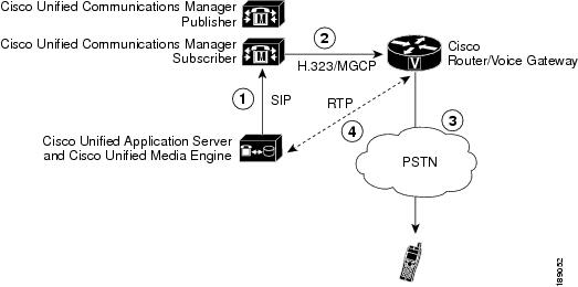
Figure 1-2 shows the call flow in which the MakeCall application makes a call to a phone on the Public Switched Telephone Network (PSTN).
1. ![]() The Cisco Unified Application Server makes a SIP call to Cisco Unified Communications Manager.
The Cisco Unified Application Server makes a SIP call to Cisco Unified Communications Manager.
2. ![]() Cisco Unified Communications Manager makes a call using H.323, MGCP, or SCCP to the gateway as a result of the call from the application server.
Cisco Unified Communications Manager makes a call using H.323, MGCP, or SCCP to the gateway as a result of the call from the application server.
3. ![]() The Cisco Voice Gateway makes a call to the PSTN as a result of the call from Cisco Unified Communications Manager.
The Cisco Voice Gateway makes a call to the PSTN as a result of the call from Cisco Unified Communications Manager.
4. ![]() When the call is answered by the phone on the PSTN, RTP streams are established between the Cisco Voice Gateway and the Cisco Unified Media Engine.
When the call is answered by the phone on the PSTN, RTP streams are established between the Cisco Voice Gateway and the Cisco Unified Media Engine.
Figure 1-2 MakeCall Application PSTN Phone Call Flow
Verifying the Trigger Parameter
The MakeCall application incorporates the Handle MakeCall script, which triggers, or initiates, when an HTTP request is received over port 8000 on the application server. Because multiple HTTP-triggered scripts can be installed on the application server, you must verify that the Handle MakeCall script uses a unique trigger parameter.
To verify the trigger parameter for the Handle MakeCall script, follow these steps:
Procedure
Step 1 ![]() Log in to the Cisco Unified Application Environment Administration.
Log in to the Cisco Unified Application Environment Administration.
Step 2 ![]() Choose Applications > List Triggers. The List Triggers page appears.
Choose Applications > List Triggers. The List Triggers page appears.
Step 3 ![]() Click MakeCall to open the MakeCall page.
Click MakeCall to open the MakeCall page.
Step 4 ![]() Verify that the URL trigger parameter value is /MakeCall. This means that the Handle MakeCall script will initiate when an HTTP request comes in with the URL http://<Application Server IP>:8000/MakeCall.
Verify that the URL trigger parameter value is /MakeCall. This means that the Handle MakeCall script will initiate when an HTTP request comes in with the URL http://<Application Server IP>:8000/MakeCall.
Step 5 ![]() Click Done.
Click Done.
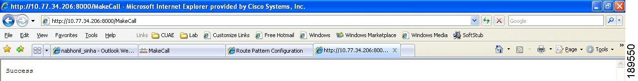
Testing the MakeCall Application
After installing the MakeCall application and verifying the trigger setting, you can test the application by opening a web browser and entering http://<Application Server IP>:8000/MakeCall.
If the outbound call succeeds, a message is displayed, as shown in Figure 1-3, and you hear `goodbye' three times. This indicates you have successfully integrated outbound calling using SIP and the Cisco Unified Application Environment.
Figure 1-3 Testing the MakeCall Application
Note ![]() If the test does not work, check the server logs for any errors. See Viewing Server Logs, page 8-2.
If the test does not work, check the server logs for any errors. See Viewing Server Logs, page 8-2.
AnswerCall Sample Application
This section contains these topics:
•![]() Defining the Trigger Parameter
Defining the Trigger Parameter
•![]() Testing the AnswerCall Application
Testing the AnswerCall Application
Overview
The AnswerCall sample application tests inbound calling to the Cisco Unified Application Server as follows:
1. ![]() Answers a call routed to the application server.
Answers a call routed to the application server.
2. ![]() Plays `goodbye' three times.
Plays `goodbye' three times.
3. ![]() Hangs up on the caller.
Hangs up on the caller.
A successful call indicates that the Cisco Unified Application Server is able to receive incoming calls.
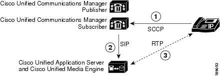
Answering a Call from an Internal IP Phone
Figure 1-4 shows the call flow in which the AnswerCall application answers a call from an internal IP phone.
1. ![]() A call is made from an IP phone to Cisco Unified Communications Manager.
A call is made from an IP phone to Cisco Unified Communications Manager.
2. ![]() The Cisco Unified Communications Manager makes an SIP call as a result of the call from the IP phone.
The Cisco Unified Communications Manager makes an SIP call as a result of the call from the IP phone.
3. ![]() When the call is answered by the Cisco Unified Application Server, RTP streams are established between the IP phone and the Cisco Unified Media Engine.
When the call is answered by the Cisco Unified Application Server, RTP streams are established between the IP phone and the Cisco Unified Media Engine.
Figure 1-4 AnswerCall Application IP Phone Call Flow
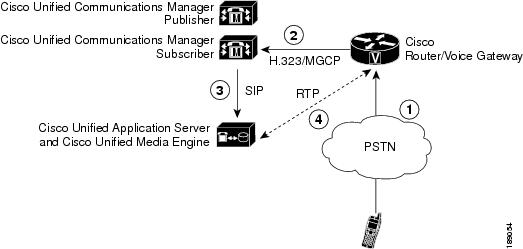
Answering a Call from the PSTN
Figure 1-5 shows the call flow in which the AnswerCall application answers a call from the PSTN.
1. ![]() A phone on the PSTN makes a call to an H.323 or MGCP gateway.
A phone on the PSTN makes a call to an H.323 or MGCP gateway.
2. ![]() The Cisco Voice Gateway makes a call to Cisco Unified Communications Manager as a result of the call from the PSTN phone.
The Cisco Voice Gateway makes a call to Cisco Unified Communications Manager as a result of the call from the PSTN phone.
3. ![]() The Cisco Unified Communications Manager makes a SIP call as a result of the call from the Cisco Voice Gateway.
The Cisco Unified Communications Manager makes a SIP call as a result of the call from the Cisco Voice Gateway.
4. ![]() When the call is answered by the application server, RTP streams are established between the Cisco Voice Gateway and the Cisco Unified Media Engine.
When the call is answered by the application server, RTP streams are established between the Cisco Voice Gateway and the Cisco Unified Media Engine.
Figure 1-5 AnswerCall Application PSTN Call Flow
Defining the Trigger Parameter
The Handle Inbound Call script, which handles calls routed to the application server, does not contain pre-defined trigger parameters. However, because it is a dial-in application (you dial a number to test it), you should define a trigger parameter for the script.
For consistency with the route pattern 5000X, which was defined in Task 9: Install, Configure, and Test Sample Applications, define a trigger parameter with the name "to" and value "50000."
To define the trigger parameter for the Handle Inbound Call script, follow these steps:
Procedure
Step 1 ![]() Log in to the Cisco Unified Application Environment Administration.
Log in to the Cisco Unified Application Environment Administration.
Step 2 ![]() Choose Applications > List Triggers. The List Triggers page appears.
Choose Applications > List Triggers. The List Triggers page appears.
Step 3 ![]() Click AnswerCall to open the AnswerCall page.
Click AnswerCall to open the AnswerCall page.
Step 4 ![]() Enter To for the parameter name.
Enter To for the parameter name.
Step 5 ![]() Enter 50000 for the value.
Enter 50000 for the value.
Step 6 ![]() Click Add Parameter.
Click Add Parameter.
Step 7 ![]() Click Done.
Click Done.
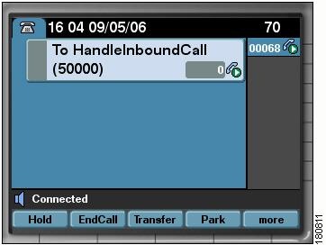
Testing the AnswerCall Application
To test AnswerCall application, call 50000 from an IP phone that is configured to dial to the previously-defined route pattern (Figure 1-6). The call should be answered immediately, play goodbye three times, then hang up.
Figure 1-6 Testing the AnswerCall Application
Note ![]() If the test does not work, check the server logs for any errors. See Viewing Server Logs, page 8-2.
If the test does not work, check the server logs for any errors. See Viewing Server Logs, page 8-2.
JTAPIConnect Sample Application
This section contains these topics:
•![]() Configuring a Monitored CTI Device Pool
Configuring a Monitored CTI Device Pool
•![]() Configuring the JTAPI Application
Configuring the JTAPI Application
•![]() Verifying the Trigger Parameter
Verifying the Trigger Parameter
•![]() Testing the JTAPIConnect Application
Testing the JTAPIConnect Application
Overview
The JTAPIConnect sample application uses JTAPI APIs and triggers to establish a call between two phones as follows:
1. ![]() The application is initiated by an HTTP request.
The application is initiated by an HTTP request.
2. ![]() Phone A calls phone B.
Phone A calls phone B.
3. ![]() Phone B answers, then hangs up.
Phone B answers, then hangs up.
Making Calls to Internal IP Phones
Figure 1-7 shows the call flow in which a call is initiated, and phone A calls phone B.
Figure 1-7 JTAPIConnect IP Phone Call Flow
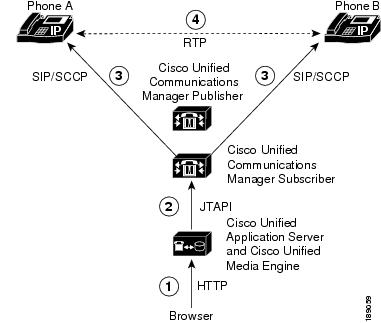
1. ![]() An HTTP request invokes the application on the Cisco Unified Application Server.
An HTTP request invokes the application on the Cisco Unified Application Server.
2. ![]() The Cisco Unified Application Server sends JTAPI requests to the CTI Manager on the Cisco Unified Communications Manager.
The Cisco Unified Application Server sends JTAPI requests to the CTI Manager on the Cisco Unified Communications Manager.
3. ![]() Phone A makes a SIP and/ or SCCP call to Phone B.
Phone A makes a SIP and/ or SCCP call to Phone B.
4. ![]() Phone B answers the call. This establishes an RTP stream between the two phones.
Phone B answers the call. This establishes an RTP stream between the two phones.
Configuring a Monitored CTI Device Pool
Procedure
Step 1 ![]() Choose Connections > List Device Pools.
Choose Connections > List Device Pools.
The List Device Pools page appears.
Step 2 ![]() Click Add.
Click Add.
The Choose Pool Type page appears.
Step 3 ![]() Select Monitored CTI Device Pool, then click Go.
Select Monitored CTI Device Pool, then click Go.
The Creating Monitored CTI Device Pool page appears.
Step 4 ![]() Select the cluster you created in Task 3: Create a SIP Connection to Cisco Unified Communications Manager from the Cluster drop-down list, then click Go.
Select the cluster you created in Task 3: Create a SIP Connection to Cisco Unified Communications Manager from the Cluster drop-down list, then click Go.
Step 5 ![]() Enter the values as described in Table A-9.
Enter the values as described in Table A-9.
|
|
|
|---|---|
Name |
Pool name. |
Primary CTI Manager |
First CTI Manager service that the Cisco Unified Application Server will try to connect to. The drop down of available options is auto-populated from any CUCM node defined that has the CTI role checked. (See Task 3: Create a SIP Connection to Cisco Unified Communications Manager.) |
Secondary CTI Manager |
Second CTI Manager service that the Cisco Unified Application Server will try to connect to if the primary is busy or inaccessible. The drop down of available options is auto-populated from any CUCM node defined that has the CTI role checked. (See Task 3: Create a SIP Connection to Cisco Unified Communications Manager.) |
Username |
User name to allow monitoring of all devices configured in the device pool. (This is the user name defined in the Cisco Unified Communications Manager with the this permission: Standard CTI Allow Control of All Devices.) |
Password/Verify Password |
Password to allow monitoring of all the devices in the device pool. (This is the associated password defined in the Cisco Unified Communications Manager.) |
Step 6 ![]() Click Save.
Click Save.
Step 7 ![]() Click the Devices tab.
Click the Devices tab.
Step 8 ![]() Click Edit. A new page appears.
Click Edit. A new page appears.
Step 9 ![]() Under Add One Device, enter the name of one of the test phones, then click Submit.
Under Add One Device, enter the name of one of the test phones, then click Submit.
Step 10 ![]() Add the second phone as described in Step 9.
Add the second phone as described in Step 9.
Configuring the JTAPI Application
To verify the configuration parameter for the JTAPIConnect application, follow these steps:
Procedure
Step 1 ![]() Log in to the Cisco Unified Application Environment Administration
Log in to the Cisco Unified Application Environment Administration
Step 2 ![]() Choose Applications > List Applications The List Applications page appears.
Choose Applications > List Applications The List Applications page appears.
Step 3 ![]() Click JTAPIConnect.
Click JTAPIConnect.
Step 4 ![]() Under Extended Configuration:
Under Extended Configuration:
•![]() In the Device1 field enter the device name of first device from the monitored device pool.
In the Device1 field enter the device name of first device from the monitored device pool.
•![]() In the Device1_Line field enter the line number of first device from the monitored device pool.
In the Device1_Line field enter the line number of first device from the monitored device pool.
•![]() In the Device2 field enter the device name of second device from the monitored device pool.
In the Device2 field enter the device name of second device from the monitored device pool.
•![]() In the Device2_Line field enter the line number of the second device from monitored device pool.
In the Device2_Line field enter the line number of the second device from monitored device pool.
Step 5 ![]() Click Apply.
Click Apply.
Step 6 ![]() Click Done.
Click Done.
Verifying the Trigger Parameter
The JTAPIConnect application triggers, or initiates when an HTTP request is received over port 8000 on the Cisco Unified Application Server. Because multiple HTTP-triggered scripts can be installed on the application server, you must verify that the application uses a unique trigger parameter. The default setting is JTAPIConnect.
To verify the trigger parameter for the JTAPIConnect application, follow these steps:
Procedure
Step 1 ![]() Log in to the Cisco Unified Application Environment Administration.
Log in to the Cisco Unified Application Environment Administration.
Step 2 ![]() Choose Applications > List Triggers. The List Triggers page appears.
Choose Applications > List Triggers. The List Triggers page appears.
Step 3 ![]() Click JTAPIConnect to open the JTAPIConnect page.
Click JTAPIConnect to open the JTAPIConnect page.
Step 4 ![]() Verify that the URL trigger parameter value is /JTAPIConnect. This means that the JTAPIConnect application will initiate when an HTTP request comes in with the URL http://<Application Server IP>:8000/JTAPIConnect.
Verify that the URL trigger parameter value is /JTAPIConnect. This means that the JTAPIConnect application will initiate when an HTTP request comes in with the URL http://<Application Server IP>:8000/JTAPIConnect.
Step 5 ![]() Click Done.
Click Done.
Testing the JTAPIConnect Application
To test the application by opening a web browser and entering http://<Application Server IP>:8000/JTAPIConnect.
Both devices (test phones) ring, then auto answer each other. After two seconds, the phones hang up.
Note ![]() If the test does not work, check the server logs for any errors. See Viewing Server Logs, page 8-2.
If the test does not work, check the server logs for any errors. See Viewing Server Logs, page 8-2.
 Feedback