Application Note for the NEC NEAX 2400 IMX TIMG Integration

Network Topology

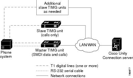
Figure 9-1 shows the required connections for a serial SMDI integration using TIMG units.

Figure 1. Connections for a Serial SMDI TIMG Integration


For more information about this integration, see Integration Description

Requirements

The phone system met the following requirements:

  • The NEC NEAX 2400 IMX phone system.

  • MCI feature II.

  • One T1 digital trunk interface card (card number PA-24DTR/DLI) for each group of 24 voice messaging ports.

Note that the following requirements for the T1 digital trunk interface card before programming the phone system:

  • The firmware must be configured to support T1 line-side signaling.

  • The card must be validated.

Programming NEC NEAX 2400 IMX Phone System for TIMG Integration

The following programming instructions are provided as an example. The specific programming for your phone system may vary depending on its configuration.


Caution

In programming the phone system, do not send calls to voice messaging ports in Unity Connection that cannot answer calls (voice messaging ports that are not set to Answer Calls). For example, if a voice messaging port is set only to Perform Message Notification, do not send calls to it.

Example of Programming for the NEC NEAX 2400 IMX Phone System in a TIMG Integration

  1. Use the AUCD command to program the phone system to send UCD call information to MCI. Assign a value of “0” to the “MCI Data Transfer” field for the applicable tenant and UCD pilot numbers.

  2. Use the programming system data table to program the ASYD settings. Each bit is part of a hexadecimal number displayed in the ASYD settings. Convert the hexadecimal number to binary to determine the individual settings.

    Table 1. Programming System Data

    System

    Index

    Bit

    Value

    Description

    1

    17

    b4

    1

    Release (blind) transfer to attendant console

    28

    b0–4

    0

    Guard timer not required

    b5

    1

    MWI controlled by MCI

    29

    b1–7

    0/1

    No/Yes: Assign I/O port for MCI output

    Port 1 = b1, port 2 = b2, and so on

    34

    b1–4

    0

    Set output to no parity and 1 stop bit

    60

    b3

    0

    UCD queuing required

    63

    b0

    1

    Release transfer for stations in service

    69

    b0

    1

    No recall, execute call forwarding on no answer

    70

    b0

    1

    Called number display, when forwarding to attendant console

    78

    b0

    1

    Calling number display enabled

    b1

    1

    Called station status display enabled

    238

    b0–7

    0

    Lamp flash rate

    246

    b3

    0

    MCI expansion set to normal

    400

    b2

    1

    Calling number information sent to MCI

    2

    6

    b0

    1

    MCI in service when terminating to a UCD group

    7

    b1

    0

    MCI out of service when terminating to attendant console

  3. Use the programming system data local data table to program the ASYDL settings. Each bit is part of a hexadecimal number displayed in the ASYDL settings. Convert the hexadecimal number to binary to determine the individual settings.

    Table 2. Programming System Data Local Data

    System

    Index

    Bit

    Value

    Description

    1

    641

    b1

    0/1

    0/1: MCI/IMX station number/phone number

    832

    b0–7

    00–FD

    Assign the FPC of the node connected to MC

    833

    b0

    0

    MWI controlled by MCI

  4. Use the ASDT command to add ports that connect to the first voice messaging port on the first TIMG unit by entering the following settings.

    Table 3. ASDT Command Settings for Adding Ports

    Field

    Setting

    TN

    Enter the tenant number, which is typically 1.

    STN

    Enter the station number.

    TEC

    Enter 11 (which sets the port type as “voice mail”). Some sites may require setting this to 3 in order to complete transfers to Virtual Line Groups (AMNO).

    RSC

    Accept the default (all route options) or enter another route service class.

    SFC

    Accept the default (all options) or enter another service feature class.

  5. In the WRT field, enter Y and press Enter.

  6. Repeat Step 4. and Step 5. for all remaining ports that connect to the voice messaging ports on the TIMG unit.

  7. Repeat Step 6. for all remaining TIMG units.

  8. Use the ASHU command to add the UCD hunt group access number (a real or virtual extension number) by entering the following settings.

    Table 4. ASHU Command Settings for Adding the Hunt Group Access Number

    Field

    Setting

    TN

    Enter the tenant number, which is typically 1.

    STN

    Enter the access number. for the hunt group.

    Edit STN

    Enter the extensions for each voice messaging port on the TIMG units, pressing Enter after each extension.

  9. Select Set.