- Preface
- Introduction
- Planning the Usage of Voice Messaging Ports in Cisco Unity Connection
- Setting Up an Avaya Definity G3 In-Band TIMG Integration with Cisco Unity Connection
- Setting Up an Avaya S8500/S8700 In-Band TIMG Integration with Cisco Unity Connection
- Setting Up a Serial (SMDI, MCI, or MD-110) TIMG Integration with Cisco Unity Connection
- Testing the Integration
- Adding New User Templates for Multiple Integrations
- Application Note for the Intecom Pointspan 6880 TIMG Integration
- Application Note for the NEC NEAX 2400 IMX TIMG Integration
- Application Note for the Nortel SL-100 TIMG Integration
- Settings for TIMG Firmware Version 5.x
- Index
TIMG Integration Guide for Cisco Unity Connection Release 10.x
Bias-Free Language
The documentation set for this product strives to use bias-free language. For the purposes of this documentation set, bias-free is defined as language that does not imply discrimination based on age, disability, gender, racial identity, ethnic identity, sexual orientation, socioeconomic status, and intersectionality. Exceptions may be present in the documentation due to language that is hardcoded in the user interfaces of the product software, language used based on RFP documentation, or language that is used by a referenced third-party product. Learn more about how Cisco is using Inclusive Language.
- Updated:
- November 11, 2014
Chapter: Application Note for the NEC NEAX 2400 IMX TIMG Integration
Application Note for the NEC NEAX 2400 IMX TIMG Integration
This is an application note for programming the NEC NEAX 2400 IMX phone system for a serial SMDI integration with Cisco Unity Connection using TIMG units. For instructions on setting up the TIMG units (media gateways) and creating the integration in Unity Connection, see the “Setting Up a Serial (SMDI, MCI, or MD-110) TIMG Integration with Cisco Unity Connection” chapter.
Network Topology
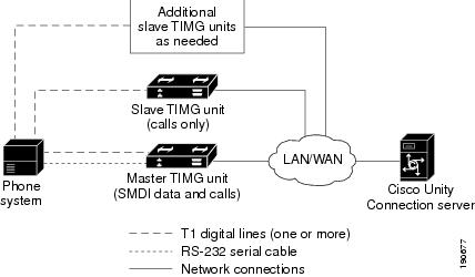
Figure 9-1 shows the required connections for a serial SMDI integration using TIMG units.
Figure 9-1 Connections for a Serial SMDI TIMG Integration
For more information about this integration, see Chapter1, “Introduction”
Requirements
The phone system met the following requirements:
- The NEC NEAX 2400 IMX phone system.
- MCI feature II.
- One T1 digital trunk interface card (card number PA-24DTR/DLI) for each group of 24 voice messaging ports.
Note that the following requirements for the T1 digital trunk interface card before programming the phone system:
–![]() The firmware must be configured to support T1 line-side signaling.
The firmware must be configured to support T1 line-side signaling.
Programming NEC NEAX 2400 IMX Phone System for TIMG Integration
The following programming instructions are provided as an example. The specific programming for your phone system may vary depending on its configuration.

Example of Programming for the NEC NEAX 2400 IMX Phone System in a TIMG Integration
1.![]() Use the AUCD command to program the phone system to send UCD call information to MCI. Assign a value of “0” to the “MCI Data Transfer” field for the applicable tenant and UCD pilot numbers.
Use the AUCD command to program the phone system to send UCD call information to MCI. Assign a value of “0” to the “MCI Data Transfer” field for the applicable tenant and UCD pilot numbers.
2.![]() Use the programming system data table to program the ASYD settings. Each bit is part of a hexadecimal number displayed in the ASYD settings. Convert the hexadecimal number to binary to determine the individual settings.
Use the programming system data table to program the ASYD settings. Each bit is part of a hexadecimal number displayed in the ASYD settings. Convert the hexadecimal number to binary to determine the individual settings.
|
|
|
|
|
|
|---|---|---|---|---|
3.![]() Use the programming system data local data table to program the ASYDL settings. Each bit is part of a hexadecimal number displayed in the ASYDL settings. Convert the hexadecimal number to binary to determine the individual settings.
Use the programming system data local data table to program the ASYDL settings. Each bit is part of a hexadecimal number displayed in the ASYDL settings. Convert the hexadecimal number to binary to determine the individual settings.
|
|
|
|
|
|
|---|---|---|---|---|
4.![]() Use the ASDT command to add ports that connect to the first voice messaging port on the first TIMG unit by entering the following settings.
Use the ASDT command to add ports that connect to the first voice messaging port on the first TIMG unit by entering the following settings.
5.![]() In the WRT field, enter Y and press Enter.
In the WRT field, enter Y and press Enter.
6.![]() Repeat Step 4. and Step 5. for all remaining ports that connect to the voice messaging ports on the TIMG unit.
Repeat Step 4. and Step 5. for all remaining ports that connect to the voice messaging ports on the TIMG unit.
7.![]() Repeat Step 6. for all remaining TIMG units.
Repeat Step 6. for all remaining TIMG units.
8.![]() Use the ASHU command to add the UCD hunt group access number (a real or virtual extension number) by entering the following settings.
Use the ASHU command to add the UCD hunt group access number (a real or virtual extension number) by entering the following settings.
|
|
|
|---|---|
Enter the extensions for each voice messaging port on the TIMG units, pressing Enter after each extension. |
 Feedback