Overview
Service graphs provide the Policy-based Redirect (PBR) feature to redirect traffic between different security zones. The use of PBR simplifies service device insertion and removal.
With PBR, the Cisco ACI fabric can redirect traffic between security zones to Layer 4 to Layer 7 devices, such as a firewall or load balancer. Even, without the need for the Layer 4 to Layer 7 device to be the default gateway for the servers or the need to perform traditional networking configuration such as Virtual Routing and Forwarding (VRF) sandwiching or VLAN stitching. For example, Cisco ACI can selectively send traffic to Layer 4 to Layer 7 devices based, for instance, on the protocol and the Layer 4 port.
This document provides information on how to deploy PBR in an intra-VRF design. It explains the steps involved in achieving the PBR use case using an unmanaged Layer 4 to Layer 7 device as a firewall.
Prerequisites
-
The Cisco ACI fabric must be up and running.
-
Cisco UCS Director must able to reach an APIC controller. The VMM domain must be configured in the APIC controller.
-
End point VMs must be configured with an IP address in the vCenter, through Cisco UCS Director.
-
ASAv is deployed with inside and outside interfaces with ACL configurations in Cisco UCS Director.
Deployment of PBR in Intra-VRF Design
The basic and common deployment of PBR consists of EPGs and PBR nodes in the same VRF instance, with each EPG in a different bridge domain. The gateway for the endpoints is the Cisco ACI fabric, which is required for PBR.
The following diagram displays the topology of deployment of PBR in between Web EPG and Application EPG in different subnets.
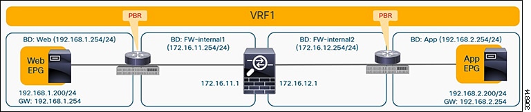
The Topology shows the intra-VRF design and the packet flows from Web EPG to App EPG. When the Web EPG sends a packet to the App EPG, the packet flow is communicated through the firewall internal1 and firewall internal2 interfaces. To filter the traffic, APIC L4-L7 policy has to be created and applied on the ACI fabric.
 Note |
After completion of the PBR configuration on the tenant, the port group is created with the respective tenant name in vCenter automatically. The port group must be mapped with virtual machines. |
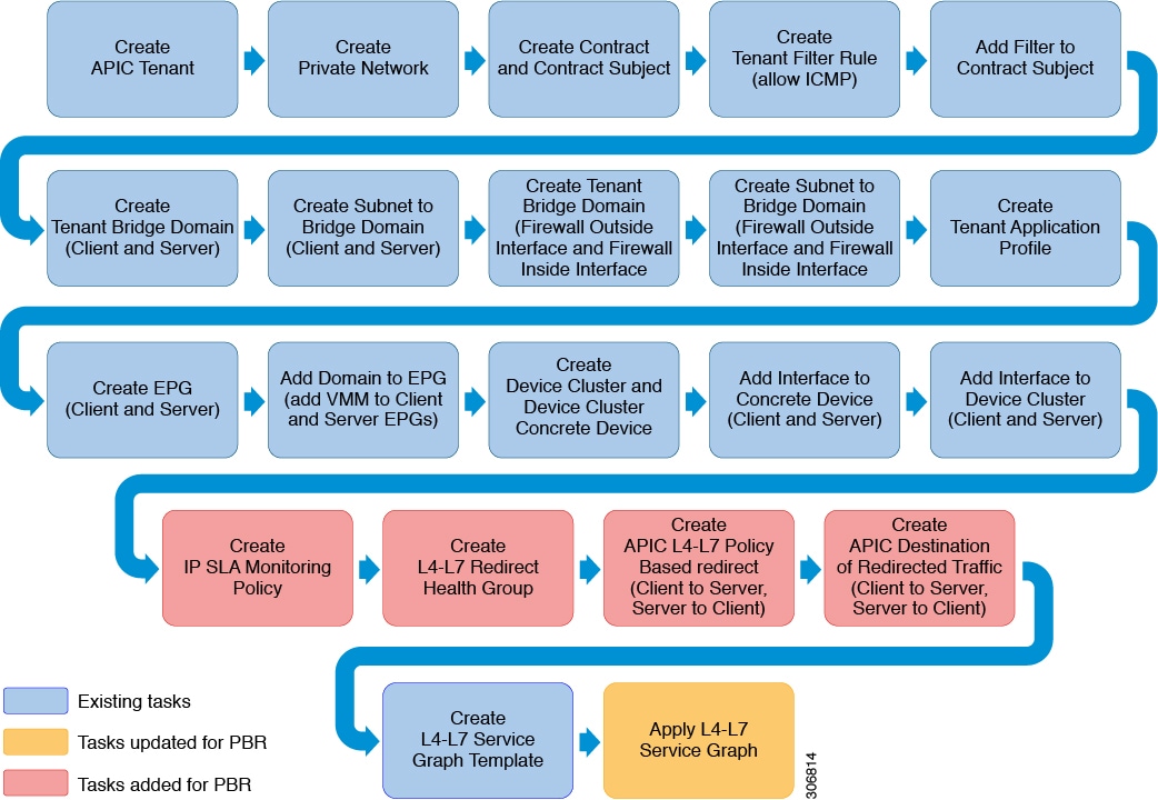
The following workflow diagram captures the workflow tasks used for PBR configuration to achieve this use case.
To achieve this use case, you have to download Cisco ACI APIC Connector Pack, Release 6.6.0.1 and upgrade to the latest version of Cisco ACI APIC. For instructions on how to upgrade a connector pack, see Cisco UCS Director Release Notes for Cisco ACI APIC Connector Pack, Release 6.6.x.x.
 Feedback