Recycling the PCB Assembly (PCBA)
The PCBA is secured to the bottom of the server chassis. To recycle the PCBA, you will need to remove some components from the server. The assemblies and subassemblies are secured to the chassis and held together by M3x0.5mm screws.
Before you begin
 Note |
For Recyclers Only! This procedure is not a standard field-service option. This procedure is for recyclers who will be reclaiming the electronics for proper disposal to comply with local eco design and e-waste regulations. |
To remove the printed circuit board assembly (PCBA), the following requirements must be met:
-
The server must be disconnected from facility power. See "Shutting Down and Powering Off the S3260 System" in the Cisco UCS S3260 Storage Server Chassis Installation and Service Guide. Go to https://www.cisco.com/c/dam/en/us/td/docs/unified_computing/ucs/s/hw/S3260/installb/S3260.pdf.
-
The server must be removed from the equipment rack.
-
The server's top cover must be removed. See in the Cisco UCS S3260 Storage Server Chassis Installation and Service Guide. Go to https://www.cisco.com/c/dam/en/us/td/docs/unified_computing/ucs/s/hw/S3260/installb/S3260.pdf.
-
All drives in the drive cage should be removed. If they are present, remove them now. See "Replacing Internal Drives" in the Cisco UCS S3260 Storage Server Chassis Installation and Service Guide. Go to https://www.cisco.com/c/dam/en/us/td/docs/unified_computing/ucs/s/hw/S3260/installb/S3260.pdf.
Procedure
| Step 1 |
Remove the mouting screws from the left and right exterior sides of the chassis. The following figure shows these screws. 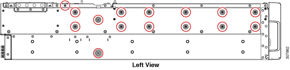
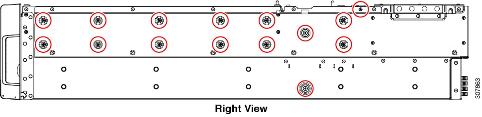 |
| Step 2 |
Remove the SSD backplane cables.
|
| Step 3 |
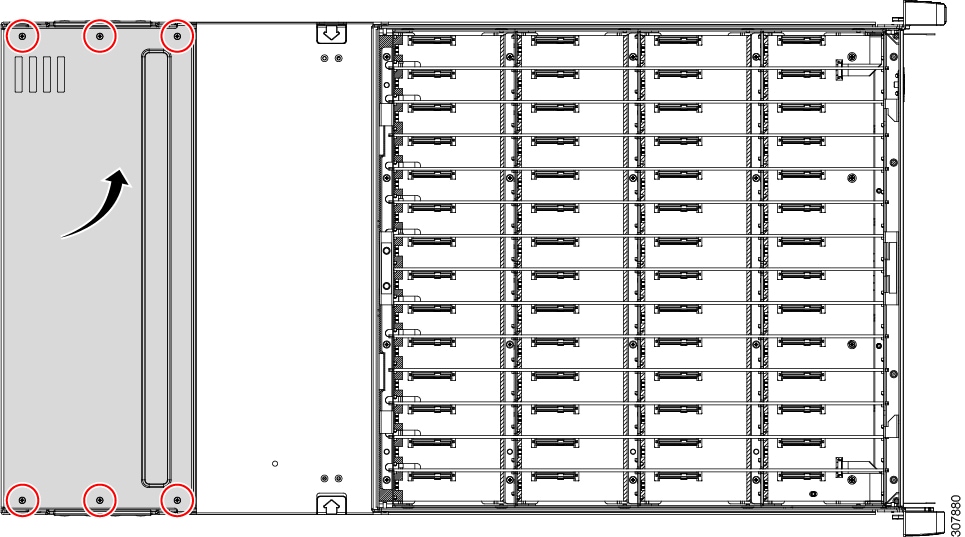
Remove the cover plate.
|
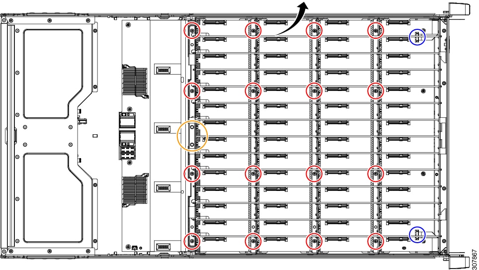
| Step 4 |
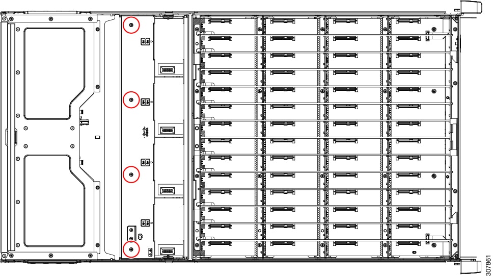
Remove the Midplane PCBA.
The following image shows the locations of these components. 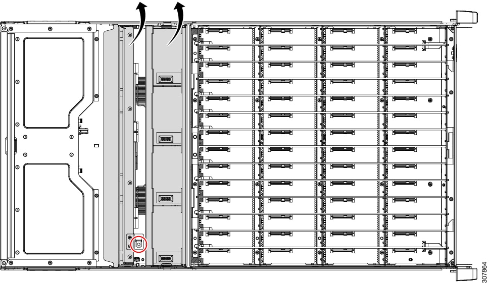
|
| Step 5 |
Disassemble the Midplane PCBA.
|
| Step 6 |
Remove the drive cage mounting screws from the front of the chassis. The following illustration shows these screws. 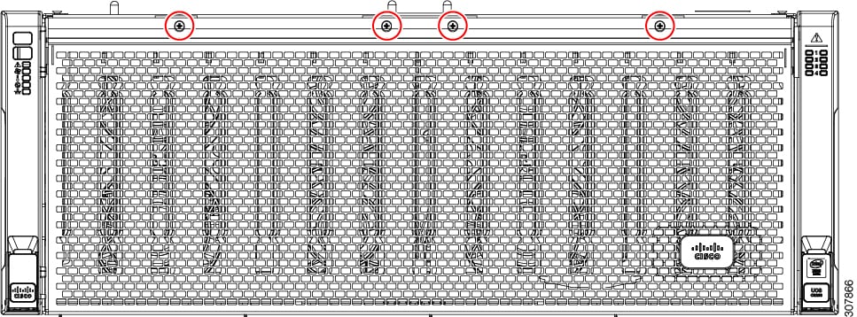
|
| Step 7 |
Open the double doors for the drive cage. |
| Step 8 |
Remove the drive cage.
|
| Step 9 |
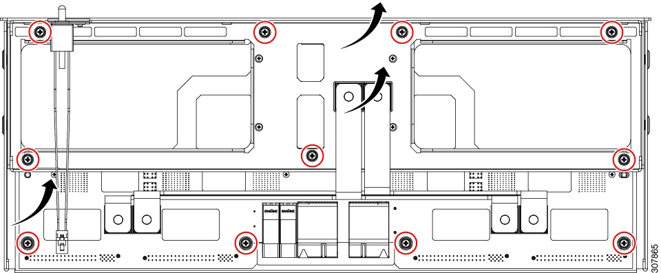
Remove the mounting screws for the motherboard and lift the motherboard out of the chassis. The following image shows the location of the screws. 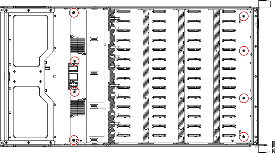
|
| Step 10 |
Dispose of the motherboard, PCBA, and all other removed components properly. |
 Feedback