Cisco UCS C3160 Server Installation and Service Guide
Bias-Free Language
The documentation set for this product strives to use bias-free language. For the purposes of this documentation set, bias-free is defined as language that does not imply discrimination based on age, disability, gender, racial identity, ethnic identity, sexual orientation, socioeconomic status, and intersectionality. Exceptions may be present in the documentation due to language that is hardcoded in the user interfaces of the product software, language used based on RFP documentation, or language that is used by a referenced third-party product. Learn more about how Cisco is using Inclusive Language.
- Updated:
- September 26, 2014
Chapter: Maintaining the Server
- Replacing Hard Drives or Solid State Drives
- Replacing Fan Modules
- Replacing a Server Node
- Replacing a Drive Expander Module
- Replacing a System I/O Controller
- Replacing a Power Supply
- Replacing DIMMs Inside the Server Node
- Replacing CPUs and Heatsinks Inside the Server Node
- Replacing a RAID Controller Card Inside the Server Node
- Replacing an RTC Battery Inside the Server Node
- Replacing an Internal USB Drive Inside the Server Node
- Installing a Trusted Platform Module (TPM) Inside the Server Node
- Replacing an Adapter Card Inside the SIOC
- Replacing an RTC Battery Inside the SIOC
Maintaining the System
This chapter describes how to diagnose system problems using LEDs. It also provides information about how to install or replace hardware components, and it includes the following sections:
Status LEDs and Buttons
This section describes the location and meaning of LEDs and buttons and includes the following topics:
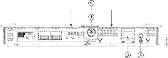
Front-Panel LEDs
Figure 3-1 shows the front-panel LEDs. Table 3-1 defines the front-panel LED states.
|
|
|
||
|
|
|
||
|
|
|
||
|
|
|
|
|
|
|
|---|---|---|
– – – |
||
Use these LEDs to indicate the location of a failing drive. Then open the system cover to find exactly which drive is failing by looking at the LEDs on the drive trays.
See Figure 3-9 for an example. In this example, the red LED indicates that the failing drive is in the right half of the internal drive compartment, in row 3. |
Rear-Panel LEDs and Buttons
Figure 3-2 shows the rear-panel LEDs and buttons. Table 3-2 defines the rear-panel LED states.
Figure 3-2 Rear-Panel LEDs and Buttons
|
|
|
|
|---|---|---|
|
|
||
– –
– – |
||
|
|
||
|
|
||
|
|
||
This LED can indicate failure of an installed drive or a failure of the module. See Table 3-3 for LED interpretations. |
||
|
||
|
|
|
|
|
|
|
|
|---|---|---|---|---|
Internal Diagnostic LEDs
Diagnostic LEDs in the Main Chassis
The diagnostic LEDs inside the main chassis compartments can be viewed while the system is powered on. See Figure 3-3 for the locations of these internal LEDs.
Figure 3-3 Internal Diagnostic LED Locations in the Main Chassis
|
|
|
||
|
|
|
|
|
|
|
|---|---|---|
Diagnostic LEDs in the Server Node
There are internal diagnostic LEDs on the edge of the server node board. These LEDs can be viewed while the server node is removed from the chassis, up to 30 minutes after AC power is removed.
There are fault LEDs for each DIMM, each CPU, the RAID card, and each system I/O controller (SIOC).
To use these LEDs to identify a failed component:
Step 1![]() Shut down and remove the server node from the system as described in Removing the Server Node Cover.
Shut down and remove the server node from the system as described in Removing the Server Node Cover.
You do not have to remove the server node cover to view the LEDs on the edge of the board.
Step 2![]() Press and hold the server node unit identification button within 30 minutes of removing the server node from the system.
Press and hold the server node unit identification button within 30 minutes of removing the server node from the system.
A fault LED that lights amber indicates a faulty component.
Figure 3-4 Internal Diagnostic LEDs on the Server Node Board
|
|
|
Preparing for System Component Installation or Replacement
This section describes how to prepare for component installation, and it includes the following topics:
- Required Equipment
- Shutting Down and Powering Off the System Chassis
- Shutting Down an Individual Server Node
- Opening the Main Chassis Top Covers
- Removing the Server Node Cover
- Removing the System I/O Controller Cover
Required Equipment
The following equipment is used to perform the procedures in this chapter:
Powering On the System
The system has two power states: standby power mode and main power mode.
- Standby power mode—When you plug power cords into the power supplies and connect to power, the system powers on to standby power mode. The front panel power button/LED lights amber. Power is supplied only to the server node service processor and the cooling fans.
- Main power mode—To power the system to main power mode, press and hold the front panel power button/LED and hold it for four seconds. The front panel power button/LED lights green. Power is supplied to all system components and any operating system on your drives can run.
Shutting Down and Powering Off the System Chassis
You can invoke a graceful shutdown or a hard shutdown by using either the Cisco Integrated Management Controller (Cisco IMC) interface or the system power button on the front panel.
To use the system power button, follow these steps:
Step 1![]() Check the color of the System Power Status LED (see the “Front-Panel LEDs” section).
Check the color of the System Power Status LED (see the “Front-Panel LEDs” section).
- Green—The system is in main power mode and must be shut down before it can be safely powered off. Go to Step 2.
- Amber—The system is already in standby mode and can be safely powered off. Go to Step 3.
Step 2![]() Invoke either a graceful shutdown or a hard shutdown:
Invoke either a graceful shutdown or a hard shutdown:

- Graceful shutdown—Press and release the Power button. The operating system performs a graceful shutdown and the system goes to standby mode, which is indicated by an amber Power Status LED.
- Emergency shutdown—Press and hold the Power button for 4 seconds to force the main power off and immediately enter standby mode.
Step 3![]() Disconnect the power cords from the power supplies in your system to completely remove AC power and power off the system.
Disconnect the power cords from the power supplies in your system to completely remove AC power and power off the system.
Shutting Down an Individual Server Node
You can invoke a graceful shutdown or a hard shutdown of a server node by using either the Cisco Integrated Management Controller (Cisco IMC) interface, or the power button that is on the face of the server node.
Shutting Down a Server Node By Using the Cisco IMC GUI
To use the Cisco IMC GUI to shut down the server node, follow these steps:
Step 1![]() Use a browser and the management IP address of the system to log in to the Cisco IMC GUI.
Use a browser and the management IP address of the system to log in to the Cisco IMC GUI.
Step 2![]() In the Navigation pane, click the Chassis menu.
In the Navigation pane, click the Chassis menu.
Step 3![]() In the Chassis menu, click Summary.
In the Chassis menu, click Summary.
Step 4![]() In the toolbar above the work pane, click the Host Power link.
In the toolbar above the work pane, click the Host Power link.
The Server Power Management dialog opens. This dialog lists all servers that are present in the system.
Step 5![]() In the Server Power Management dialog, select one of the following buttons for the server that you want to shut down:
In the Server Power Management dialog, select one of the following buttons for the server that you want to shut down:
- Shut Down—Performs a graceful shutdown of the operating system.
- Power Off—Powers off the chosen server, even if tasks are running on that server.
It is safe to remove the server node from the chassis when the Chassis Status pane shows the Power State as Off for the server node that you are removing.
The physical power button on the server node face also turns amber when it is safe to remove the server node from the chassis.
Shutting Down a Server Node By Using the Power Button on the Server Node
To use the physical server node power button to shut down the server node only, follow these steps:
Step 1![]() Check the color of the server node power status LED:
Check the color of the server node power status LED:
- Green—The server node is powered on. Go to step Step 2
- Amber—the server node is powered off. It is safe to remove the server node from the chassis.
Step 2![]() Invoke either a graceful shutdown or a hard shutdown:
Invoke either a graceful shutdown or a hard shutdown:
- Graceful shutdown—Press and release the Power button. The software performs a graceful shutdown of the server node.
- Emergency shutdown—Press and hold the Power button for 4 seconds to force the power off the server node.
When the server node power button turns amber, it is safe to remove the server node from the chassis.
Opening the Main Chassis Top Covers
This system has three hinged top covers on the main chassis. Opening these covers gives access to the internal-drives compartment and the fan module compartment.

Note![]() The internal drives and cooling fans in the system are hot-swappable and are accessed by opening the top covers. When you rack and cable the system, be sure to allow enough slack in the power and other cables so that the system can be pulled out on the slide rails far enough to allow clearance for opening the top covers.
The internal drives and cooling fans in the system are hot-swappable and are accessed by opening the top covers. When you rack and cable the system, be sure to allow enough slack in the power and other cables so that the system can be pulled out on the slide rails far enough to allow clearance for opening the top covers.
Step 1![]() Open the left or right internal-drive compartment cover to access the hot-swappable internal drives:
Open the left or right internal-drive compartment cover to access the hot-swappable internal drives:
a.![]() For either the right or left side cover, pull the latch release buttons on both latches toward the outer edges of the chassis. This causes the spring-loaded latches to pop up.
For either the right or left side cover, pull the latch release buttons on both latches toward the outer edges of the chassis. This causes the spring-loaded latches to pop up.
b.![]() With both latches open, swing open the hinged cover from the center toward the outside.
With both latches open, swing open the hinged cover from the center toward the outside.
c.![]() To secure the cover, close it down flat and then push both latches flat until they click and lock.
To secure the cover, close it down flat and then push both latches flat until they click and lock.
Step 2![]() Open the fan compartment cover to access the hot-swappable fan modules:
Open the fan compartment cover to access the hot-swappable fan modules:
a.![]() Push both latch-buttons toward the center.
Push both latch-buttons toward the center.
b.![]() While holding in both latch-buttons, open the hinged cover from the center toward the rear of the system.
While holding in both latch-buttons, open the hinged cover from the center toward the rear of the system.
c.![]() To secure the cover, hold in both latch-buttons while you close the cover flat. Release the latch-buttons.
To secure the cover, hold in both latch-buttons while you close the cover flat. Release the latch-buttons.
Figure 3-5 Opening the Top Covers
|
|
|
||
|
|
|
Removing the Server Node Cover
Note![]() You do not have to slide the system out of the rack to remove the server node from the rear of the system.
You do not have to slide the system out of the rack to remove the server node from the rear of the system.
Step 1![]() Shut down and remove power from the entire system, as described in Shutting Down and Powering Off the System Chassis.
Shut down and remove power from the entire system, as described in Shutting Down and Powering Off the System Chassis.
Step 2![]() Remove a server node from the system:
Remove a server node from the system:
a.![]() Grasp the two ejector levers and pinch their latches to release the levers (see Figure 3-15).
Grasp the two ejector levers and pinch their latches to release the levers (see Figure 3-15).
b.![]() Rotate both levers to the outside at the same time to evenly disengage the server node from its midplane connectors.
Rotate both levers to the outside at the same time to evenly disengage the server node from its midplane connectors.
c.![]() Pull the server node straight out from the system.
Pull the server node straight out from the system.
Step 3![]() Remove the cover from the server node:
Remove the cover from the server node:
a.![]() Lift the latch handle to an upright position (see Figure 3-6).
Lift the latch handle to an upright position (see Figure 3-6).
b.![]() Turn the latch handle 90-degrees to release the lock.
Turn the latch handle 90-degrees to release the lock.
c.![]() Slide the cover toward the rear (toward the rear-panel buttons) and then lift it from the server node.
Slide the cover toward the rear (toward the rear-panel buttons) and then lift it from the server node.
Step 4![]() Replace the server node cover:
Replace the server node cover:
a.![]() Set the cover in place on the server node, offset about one inch toward the rear. Pegs on the inside of the cover must set into the tracks on the server node base.
Set the cover in place on the server node, offset about one inch toward the rear. Pegs on the inside of the cover must set into the tracks on the server node base.
b.![]() Push the cover forward until it stops.
Push the cover forward until it stops.
c.![]() Turn the latch handle 90-degrees to close the lock.
Turn the latch handle 90-degrees to close the lock.
d.![]() Fold the latch handle flat.
Fold the latch handle flat.
a.![]() With the two ejector levers open, align the new server node with the empty bay.
With the two ejector levers open, align the new server node with the empty bay.
b.![]() Push the server node into the bay until it engages with the midplane connectors and is flush with the chassis.
Push the server node into the bay until it engages with the midplane connectors and is flush with the chassis.
c.![]() Rotate both ejector levers toward the center until they lay flat and their latches lock into the rear of the server node.
Rotate both ejector levers toward the center until they lay flat and their latches lock into the rear of the server node.
Step 6![]() Replace power cords and then power on the system by pressing and holding the power button on the front handle for four seconds.
Replace power cords and then power on the system by pressing and holding the power button on the front handle for four seconds.
Figure 3-6 Removing the Server Node Cover
|
|
|
Removing the System I/O Controller Cover
Note![]() You do not have to slide the system out of the rack to remove the SIOC from the rear of the system.
You do not have to slide the system out of the rack to remove the SIOC from the rear of the system.
Step 1![]() Shut down and remove power from the entire system, as described in Shutting Down and Powering Off the System Chassis.
Shut down and remove power from the entire system, as described in Shutting Down and Powering Off the System Chassis.
Step 2![]() Remove the SIOC from the system:
Remove the SIOC from the system:
a.![]() Loosen the single captive thumbscrew on the SIOC and then open its two hinged levers to evenly disengage the SIOC from its backplane connector.
Loosen the single captive thumbscrew on the SIOC and then open its two hinged levers to evenly disengage the SIOC from its backplane connector.
b.![]() Pull the SIOC from the system and set it on an antistatic work surface.
Pull the SIOC from the system and set it on an antistatic work surface.
a.![]() Press the release button on the cover. See Figure 3-7.
Press the release button on the cover. See Figure 3-7.
b.![]() Push the cover forward (toward the Molex connectors).
Push the cover forward (toward the Molex connectors).
c.![]() Lift the cover straight up off the SIOC.
Lift the cover straight up off the SIOC.
Step 4![]() Replace the SIOC cover:
Replace the SIOC cover:
a.![]() Set the cover back in place.
Set the cover back in place.
b.![]() Slide the cover toward the rear (toward the rear panel buttons) until it stops and the release button clicks and locks.
Slide the cover toward the rear (toward the rear panel buttons) until it stops and the release button clicks and locks.
Step 5![]() Replace the SIOC to the system:
Replace the SIOC to the system:
a.![]() Push the SIOC into its bay until it stops against the internal midplane.
Push the SIOC into its bay until it stops against the internal midplane.
b.![]() Close the two levers on the SIOC to fully engage the SIOC connector with its midplane.
Close the two levers on the SIOC to fully engage the SIOC connector with its midplane.
c.![]() Tighten the thumbscrew on the SIOC levers.
Tighten the thumbscrew on the SIOC levers.
Step 6![]() Replace power cables and then power on the system by pressing and holding the power button on the front handle for four seconds.
Replace power cables and then power on the system by pressing and holding the power button on the front handle for four seconds.
Figure 3-7 Removing the SIOC Cover
|
|
|
Installing or Replacing System Components

Warning![]() Blank faceplates and cover panels serve three important functions: they prevent exposure to hazardous voltages and currents inside the chassis; they contain electromagnetic interference (EMI) that might disrupt other equipment; and they direct the flow of cooling air through the chassis. Do not operate the system unless all cards, faceplates, front covers, and rear covers are in place.
Blank faceplates and cover panels serve three important functions: they prevent exposure to hazardous voltages and currents inside the chassis; they contain electromagnetic interference (EMI) that might disrupt other equipment; and they direct the flow of cooling air through the chassis. Do not operate the system unless all cards, faceplates, front covers, and rear covers are in place.
Statement 1029
This section describes how to install and replace system components, and it includes the following topics:
- Replacing Hard Drives or Solid State Drives
- Replacing Fan Modules
- Replacing a Server Node
- Replacing a Drive Expander Module
- Replacing a System I/O Controller
- Replacing a Power Supply
- Replacing DIMMs Inside the Server Node
- Replacing CPUs and Heatsinks Inside the Server Node
- Replacing a RAID Controller Card Inside the Server Node
- Replacing an RTC Battery Inside the Server Node
- Replacing an Internal USB Drive Inside the Server Node
- Installing a Trusted Platform Module (TPM) Inside the Server Node
- Replacing an Adapter Card Inside the SIOC
- Replacing an RTC Battery Inside the SIOC
- Service Headers on the Server Node Board
See also Replaceable Component Locations.
Replacing Hard Drives or Solid State Drives
4K Sector Format Drives Considerations
- You must boot 4K sector format drives in UEFI mode, not legacy mode. See Setting Up Booting in UEFI Mode in the BIOS Setup Utility or Setting Up Booting in UEFI Mode in the Cisco IMC GUI.
- Do not configure 4K sector format and 512-byte sector format drives as part of the same RAID volume.
- Operating system support on 4K sector drives is as follows: Windows: Win2012 and Win2012R2; Linux: RHEL 6.5, 6.6, 6.7, 7.0, 7.2; SLES 11 SP3, and SLES 12.
ESXi/Vmware is not supported.
Setting Up Booting in UEFI Mode in the BIOS Setup Utility
Step 1![]() Use a web browser and the management IP address of the system to log into the Cisco IMC GUI management interface.
Use a web browser and the management IP address of the system to log into the Cisco IMC GUI management interface.
Step 2![]() Select Compute and then Server 1.
Select Compute and then Server 1.
Step 3![]() Click Launch KVM to open a virtual KVM window for the server node.
Click Launch KVM to open a virtual KVM window for the server node.
Step 4![]() In the Launch KVM dialog, select Server 1 and click Launch.
In the Launch KVM dialog, select Server 1 and click Launch.
Step 5![]() Reboot server node 1. Watch the KVM window for the prompt to press F2.
Reboot server node 1. Watch the KVM window for the prompt to press F2.
Step 6![]() Enter the BIOS setup utility by pressing the F2 key when prompted during bootup.
Enter the BIOS setup utility by pressing the F2 key when prompted during bootup.
Step 7![]() Go to the Boot Options tab.
Go to the Boot Options tab.
Step 8![]() Set UEFI Boot Options to Enabled.
Set UEFI Boot Options to Enabled.
Step 9![]() Under Boot Option Priorities, set your OS installation media (such as a virtual DVD) as your
Under Boot Option Priorities, set your OS installation media (such as a virtual DVD) as your
Boot Option #1.
Step 10![]() Go to the Advanced tab.
Go to the Advanced tab.
Step 11![]() Select LOM and PCIe Slot Configuration.
Select LOM and PCIe Slot Configuration.
Step 12![]() Set the PCIe Slot ID: HBA Option ROM to UEFI Only.
Set the PCIe Slot ID: HBA Option ROM to UEFI Only.
Step 13![]() Press F10 to save changes and exit the BIOS setup utility. Allow the server to reboot.
Press F10 to save changes and exit the BIOS setup utility. Allow the server to reboot.
Step 14![]() After the server reboots and the OS installs, verify the installation:
After the server reboots and the OS installs, verify the installation:
a.![]() Enter the BIOS setup utility by pressing the F2 key when prompted during bootup.
Enter the BIOS setup utility by pressing the F2 key when prompted during bootup.
b.![]() Go to the Boot Options tab.
Go to the Boot Options tab.
c.![]() Under Boot Option Priorities, verify that the OS you installed is listed as your Boot Option #1.
Under Boot Option Priorities, verify that the OS you installed is listed as your Boot Option #1.
Setting Up Booting in UEFI Mode in the Cisco IMC GUI
Step 1![]() Use a web browser and the management IP address of the system to log into the Cisco IMC GUI management interface.
Use a web browser and the management IP address of the system to log into the Cisco IMC GUI management interface.
Step 2![]() Select Compute and then Server 1.
Select Compute and then Server 1.
Step 4![]() Under BIOS Properties, set Configured Boot Order to UEFI.
Under BIOS Properties, set Configured Boot Order to UEFI.
Step 6![]() Click Configure Boot Order.
Click Configure Boot Order.
Step 7![]() Select the Advanced tab.
Select the Advanced tab.
Step 9![]() In the Add Local Disk dialog, enter the information for the 4K sector format drive. Enter a name and specify Slot M.
In the Add Local Disk dialog, enter the information for the 4K sector format drive. Enter a name and specify Slot M.
Step 11![]() Click Add Virtual Media.
Click Add Virtual Media.
Step 12![]() In the Add Virtual Media dialog, enter a name for your OS installation virtual media.
In the Add Virtual Media dialog, enter a name for your OS installation virtual media.
Step 15![]() Click Launch KVM to open a virtual KVM window for the server node.
Click Launch KVM to open a virtual KVM window for the server node.
Step 16![]() In the Launch KVM dialog, select Server 1 and click Launch.
In the Launch KVM dialog, select Server 1 and click Launch.
Step 17![]() Activate virtual media. Pull down the Virtual Media menu on the KVM window and select Activate Virtual Devices.
Activate virtual media. Pull down the Virtual Media menu on the KVM window and select Activate Virtual Devices.
Step 18![]() Reboot the server node.
Reboot the server node.
Step 19![]() Press F6 during the boot to enter the boot device menu.
Press F6 during the boot to enter the boot device menu.
Step 20![]() Select UEFI: Cisco vKVM-Mapped vDVD and press Enter.
Select UEFI: Cisco vKVM-Mapped vDVD and press Enter.
Step 21![]() Proceed with the installation of your OS.
Proceed with the installation of your OS.
After the OS installs and the system reboots, your OS is listed as a boot option.
Replacing Hard Drives in the Internal Drive Compartment
Internal Drive Population Guidelines
The system has 56 internal drive bays in the main chassis. Figure 3-8 shows the internal drive bay numbering. When populating internal drives, follow these guidelines:
- Populate drive bays starting from the lowest-numbered bays to the highest.
- The four colored boxes shown in Figure 3-8 represent the four power groups in which power is distributed to the drive bays. This might be useful for troubleshooting power rail problems.
- When ordering the system, it is configurable with disk multipacks. The supported configurations of multipacks are listed below. See the Cisco UCS C3160 Rack Server Spec Sheet for hardware ordering and configuration information.
–![]() The UCSC-C3X60-14HD4, UCSC-C3X60-28HD4, and UCSC-C3X60-42HD4 multipacks can be selected along with the UCSC-C3X60-SSD4 multipack.
The UCSC-C3X60-14HD4, UCSC-C3X60-28HD4, and UCSC-C3X60-42HD4 multipacks can be selected along with the UCSC-C3X60-SSD4 multipack.
–![]() The UCSC-C3X60-56HD4 multipack cannot be selected with any other multipack.
The UCSC-C3X60-56HD4 multipack cannot be selected with any other multipack.
–![]() The UCSC-C3X60-14HD6, UCSC-C3X60-28HD6, and UCSC-C3X60-42HD6 multipacks can be selected along with the UCSC-C3X60-SSD6 multipack.
The UCSC-C3X60-14HD6, UCSC-C3X60-28HD6, and UCSC-C3X60-42HD6 multipacks can be selected along with the UCSC-C3X60-SSD6 multipack.
–![]() The UCSC-C3X60-56HD6 multipack cannot be selected with any other multipack.
The UCSC-C3X60-56HD6 multipack cannot be selected with any other multipack.
–![]() You cannot mix 4 TB SAS-2 multipacks with 6 TB SAS-3 multipacks.
You cannot mix 4 TB SAS-2 multipacks with 6 TB SAS-3 multipacks.
Figure 3-8 Internal Drive Bay Numbering
Identifying a Faulty Internal Drive
The system has internal-drive fault LEDs on the right-front handle (see Figure 3-1). Use these LEDs to get an indication of the location of a failing drive.
Step 1![]() Observe the internal-drive fault LEDs on the right-front handle.
Observe the internal-drive fault LEDs on the right-front handle.
- The two columns of LEDs correspond to the two halves of the internal drive compartment (under either the right- or left-side top cover).
- The four numbered rows of LEDs correspond to the four horizontal rows of drive bays (14 drive bays in each row).
See Figure 3-9 for an example. In this example, the amber LED indicates that the failing drive is in the right half of the internal drive compartment, in row 3.
Step 2![]() Open the right- or left-side cover and look at the fault LEDs on the drive trays.
Open the right- or left-side cover and look at the fault LEDs on the drive trays.
A solid amber fault LED indicates a failed drive.
Figure 3-9 Internal-Drive Status LED Example
|
|
Internal-drive fault LEDs on right-front handle of system, indicating faulty drive in right side of row 3 |
|
|
|
|
|
Replacing Internal Drives
Note![]() SAS/SATA drives are hot-swappable and can be replaced without removing power from the system.
SAS/SATA drives are hot-swappable and can be replaced without removing power from the system.
Step 1![]() Slide the system out the front of the rack far enough so that you can open the top cover.
Slide the system out the front of the rack far enough so that you can open the top cover.
Step 2![]() Identify a failing drive as described in Identifying a Faulty Drive Expander Module Drive
Identify a failing drive as described in Identifying a Faulty Drive Expander Module Drive
Step 3![]() Open the internal-drive compartment cover.
Open the internal-drive compartment cover.
a.![]() Press the release button on the drive carrier. The drive lever pops up.
Press the release button on the drive carrier. The drive lever pops up.
b.![]() Lift the drive lever to the fully open, 90-degree position, then lift the drive straight up out of its bay.
Lift the drive lever to the fully open, 90-degree position, then lift the drive straight up out of its bay.
Spare drives are already installed in a carrier, so it is not necessary to remove the old drive from its carrier.
Note![]() Observe the drive population guidelines in Internal Drive Population Guidelines.
Observe the drive population guidelines in Internal Drive Population Guidelines.
a.![]() Align the new drive with the empty bay. Orient the drive so that its connector aligns with the connector on the board.
Align the new drive with the empty bay. Orient the drive so that its connector aligns with the connector on the board.
b.![]() Lower the drive until it touches the board connector and the drive lever begins to close.
Lower the drive until it touches the board connector and the drive lever begins to close.
c.![]() Press the drive lever down flat until it clicks and locks.
Press the drive lever down flat until it clicks and locks.
Step 6![]() Close the chassis cover and push the system back into the rack.
Close the chassis cover and push the system back into the rack.
Figure 3-10 Internal Drive Carrier Features
|
|
|
||
|
|
|
Replacing Hard Drives in the Optional Drive Expander Module
Drive Expander Module Drives Population Guidelines
The optional drive expander module can hold up to four 3.5-inch drives. Drive numbering is shown in Figure 3-11. When populating these drives, follow these guidelines.
Figure 3-11 Drive Expander Module and Solid State Drive Numbering
Identifying a Faulty Drive Expander Module Drive
Each drive carrier has a fault LED that lights solid amber to indicate a failing drive.
Replacing Drive Expander Module Drives
Note![]() SAS/SATA drives are hot-swappable and can be replaced without removing power from the system.
SAS/SATA drives are hot-swappable and can be replaced without removing power from the system.
Step 1![]() Identify a failing drive as described in Identifying a Faulty Drive Expander Module Drive.
Identify a failing drive as described in Identifying a Faulty Drive Expander Module Drive.
a.![]() Press the release button on the drive carrier. The drive lever pops up.
Press the release button on the drive carrier. The drive lever pops up.
b.![]() Lift the drive lever to the fully open position, then pull the drive straight up out of its bay.
Lift the drive lever to the fully open position, then pull the drive straight up out of its bay.
Spare drives are already installed in a carrier, so it is not necessary to remove the old drive from its carrier.
Note![]() Observe the drive population guidelines in Drive Expander Module Drives Population Guidelines.
Observe the drive population guidelines in Drive Expander Module Drives Population Guidelines.
a.![]() Align the new drive with the empty bay and then push the drive in until it touches the board connector and the drive lever begins to close.
Align the new drive with the empty bay and then push the drive in until it touches the board connector and the drive lever begins to close.
b.![]() Press the drive lever down flat until it clicks and locks.
Press the drive lever down flat until it clicks and locks.
Figure 3-12 Drive Expander Module Drive Carrier Features
|
|
|
||
|
|
|
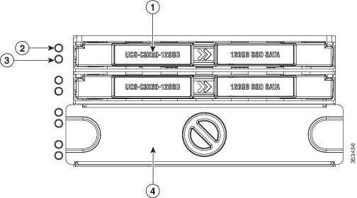
Replacing Solid State Drives in the Rear Panel Solid State Drive Bays
This section contains the following topics:
- Solid State Drive Population Guidelines
- Replacing Solid State Drives
- Selecting SATA Mode in the BIOS for SSDs
Note![]() The two SSDs can be mirrored in a RAID 1 configuration when managed in advanced host controller interface (AHCI) mode through your Windows or Linux operating system. The AHCI SATA mode must be enabled in the BIOS, as described in Selecting SATA Mode in the BIOS for SSDs.
The two SSDs can be mirrored in a RAID 1 configuration when managed in advanced host controller interface (AHCI) mode through your Windows or Linux operating system. The AHCI SATA mode must be enabled in the BIOS, as described in Selecting SATA Mode in the BIOS for SSDs.
Solid State Drive Population Guidelines
There are two supported bays for solid state drives in the rear panel. Drive numbering is shown in Figure 3-11. When populating these drives, follow these guidelines.
Note![]() At this time, only the top two solid state drive bays are supported (see Figure 3-11).
At this time, only the top two solid state drive bays are supported (see Figure 3-11).
Replacing Solid State Drives
Note![]() Solid state drives are hot-swappable and can be replaced without removing power from the system.
Solid state drives are hot-swappable and can be replaced without removing power from the system.
Step 1![]() Remove a faulty solid state drive:
Remove a faulty solid state drive:
a.![]() Grasp and pinch the release latch toward the center.
Grasp and pinch the release latch toward the center.
b.![]() Pull the solid state drive straight out of the bay.
Pull the solid state drive straight out of the bay.
Step 2![]() Install a new solid state drive:
Install a new solid state drive:
Note![]() Observe the drive population guidelines in Solid State Drive Population Guidelines.
Observe the drive population guidelines in Solid State Drive Population Guidelines.
a.![]() Align the new drive with the empty bay (with the label facing up) and then push the drive in until it touches the board connector.
Align the new drive with the empty bay (with the label facing up) and then push the drive in until it touches the board connector.
b.![]() Grasp and pinch the release latch toward the center while you push the drive fully into the bay, and then release the release latch.
Grasp and pinch the release latch toward the center while you push the drive fully into the bay, and then release the release latch.
Figure 3-13 Solid State Drive Bay Features
|
|
|
||
|
|
|
Blanking panel over lower two bays, which are not used at this time |
Selecting SATA Mode in the BIOS for SSDs
The default SATA mode for controlling the SSDs is AHCI Mode. If you want to control the SSD pair in AHCI mode, no further steps are necessary.
Step 1![]() Boot the server node and press F2 when prompted to enter the BIOS Setup utility for that server node.
Boot the server node and press F2 when prompted to enter the BIOS Setup utility for that server node.
Step 2![]() In the utility, choose the Advanced tab, and then choose SATA Configuration.
In the utility, choose the Advanced tab, and then choose SATA Configuration.
Step 3![]() Set SATA Mode to your choice:
Set SATA Mode to your choice:
- Disabled—The embedded RAID controller is disabled.
- AHCI Mode [Default]—Advanced host controller interface. You can manage the SSD pair by using your operating system’s storage management feature.
Step 4![]() Press F10 to save your changes and exit the utility.
Press F10 to save your changes and exit the utility.
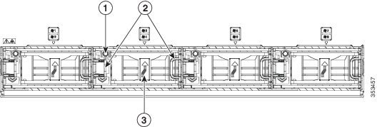
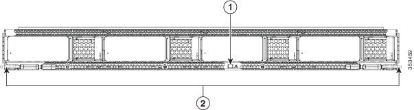
Replacing Fan Modules
Each fan module contains two fans. See Figure 3-14 for the fan numbering. The odd-numbered fan is at the top of the fan module and the even-numbered fan is at the bottom of the fan module.
You do not have to shut down or power off the system to replace fan modules because they are hot-swappable.

Tip![]() Each fan module has a fault LED that lights amber if the fan module fails.
Each fan module has a fault LED that lights amber if the fan module fails.
Step 1![]() Slide the system out the front of the rack far enough so that you can open the fan compartment cover.
Slide the system out the front of the rack far enough so that you can open the fan compartment cover.
Step 2![]() Open the fan compartment cover as described in Opening the Main Chassis Top Covers.
Open the fan compartment cover as described in Opening the Main Chassis Top Covers.
a.![]() Grasp the two latches on the top of the fan and pinch them toward the center.
Grasp the two latches on the top of the fan and pinch them toward the center.
b.![]() Lift the fan module straight out of the bay.
Lift the fan module straight out of the bay.
Step 4![]() Install a new fan module:
Install a new fan module:
Note![]() The arrow on the fan module that indicates the air flow direction should point to the rear of the server.
The arrow on the fan module that indicates the air flow direction should point to the rear of the server.
a.![]() Align the fan module with the bay so that the connector on the bottom of the fan module is aligned with the socket on the floor of the chassis.
Align the fan module with the bay so that the connector on the bottom of the fan module is aligned with the socket on the floor of the chassis.
b.![]() Lower the fan module until it touches the socket, then push down firmly until the latch locks.
Lower the fan module until it touches the socket, then push down firmly until the latch locks.
Step 5![]() Close the fan compartment cover and then push the system back into the rack.
Close the fan compartment cover and then push the system back into the rack.
Figure 3-14 Fan Modules (Top View)
|
|
|
||
|
|
|
Replacing a Server Node
The system can support one server node. The server node must be in the uppermost bay of the system.
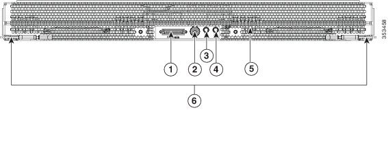
Figure 3-15 Server Node External Features
|
|
|
||
|
|
|
||
|
|
|
The server node is accessed from the rear of the system, so you do not have to pull the system out from the rack.
Step 1![]() Optional—Export the Cisco IMC configuration from the server that you are replacing so that you can import it to the replacement server node. If you choose to do this, use the procedure in Exporting Cisco IMC Configuration From a Server Node, then return to the next step.
Optional—Export the Cisco IMC configuration from the server that you are replacing so that you can import it to the replacement server node. If you choose to do this, use the procedure in Exporting Cisco IMC Configuration From a Server Node, then return to the next step.
Note![]() You do not have to power off the chassis in the next step. Replacement with chassis powered on is supported if you shut down the server node before removal.
You do not have to power off the chassis in the next step. Replacement with chassis powered on is supported if you shut down the server node before removal.
Step 2![]() Shut down the server node by using the software interface or by pressing the node power button, as described in Shutting Down an Individual Server Node.
Shut down the server node by using the software interface or by pressing the node power button, as described in Shutting Down an Individual Server Node.
Step 3![]() Remove a server node from the system:
Remove a server node from the system:
a.![]() Grasp the two ejector levers and pinch their latches to release the levers (see Figure 3-15).
Grasp the two ejector levers and pinch their latches to release the levers (see Figure 3-15).
b.![]() Rotate both levers to the outside at the same time to evenly disengage the server node from its midplane connectors.
Rotate both levers to the outside at the same time to evenly disengage the server node from its midplane connectors.
c.![]() Pull the server node straight out from the system.
Pull the server node straight out from the system.
a.![]() With the two ejector levers open, align the new server node with the empty bay.
With the two ejector levers open, align the new server node with the empty bay.
Note![]() The server node must be installed into the top bay, as shown in Figure 1-2.
The server node must be installed into the top bay, as shown in Figure 1-2.
b.![]() Push the server node into the bay until it engages with the midplane connectors and is flush with the chassis.
Push the server node into the bay until it engages with the midplane connectors and is flush with the chassis.
c.![]() Rotate both ejector levers toward the center until they lay flat and their latches lock into the rear of the server node.
Rotate both ejector levers toward the center until they lay flat and their latches lock into the rear of the server node.
Step 5![]() Replace power cords and then power on the system by pressing and holding the power button on the front handle for four seconds.
Replace power cords and then power on the system by pressing and holding the power button on the front handle for four seconds.
Step 6![]() Perform initial setup on the new server to assign an IP address and your other preferred network settings. See Initial Server Setup.
Perform initial setup on the new server to assign an IP address and your other preferred network settings. See Initial Server Setup.
Step 7![]() Optional—Import the Cisco IMC configuration that you saved in step 1. If you choose to do this, use the procedure in Importing Cisco IMC Configuration To a Server Node.
Optional—Import the Cisco IMC configuration that you saved in step 1. If you choose to do this, use the procedure in Importing Cisco IMC Configuration To a Server Node.
Exporting Cisco IMC Configuration From a Server Node
This operation can be performed using either the GUI or CLI interface of the Cisco IMC. The example in this procedure uses the CLI commands. For more information see Exporting a Cisco IMC Configuration in the CLI and GUI guides here: Configuration Guides.
Step 1![]() Log in to the IP address and CLI interface of the server node that you are replacing.
Log in to the IP address and CLI interface of the server node that you are replacing.
Step 2![]() Enter the following commands as you are prompted:
Enter the following commands as you are prompted:
Server# scope cimc
Server /cimc# scope import-export
Server /cimc/import-export# export-config <protocol> <ip-address> <path-and-filename>
Step 3![]() Enter the user name, password, and pass phrase.
Enter the user name, password, and pass phrase.
This sets the user name password, and pass phrase for the file that you are exporting. The export operation begins after you enter a pass phrase, which can be anything that you choose.
To determine whether the export operation has completed successfully, use the show detail command. To abort the operation, type CTRL+C.
The following is an example of an export operation. In this example, the TFTP protocol is used to export the configuration to IP address 192.0.2.34, in file /ucs/backups/cimc5.xml.
Importing Cisco IMC Configuration To a Server Node
This operation can be performed using either the GUI or CLI interface of the Cisco IMC. The example in this procedure uses the CLI commands. For more information see Importing a Cisco IMC Configuration in the CLI and GUI guides here: Configuration Guides.
Step 1![]() Log in to the IP address and CLI interface of the new server node.
Log in to the IP address and CLI interface of the new server node.
Step 2![]() Enter the following commands as you are prompted:
Enter the following commands as you are prompted:
Server# scope cimc
Server /cimc# scope import-export
Server /cimc/import-export# import-config <protocol> <ip-address> <path-and-filename>
Step 3![]() Enter the user name, password, and pass phrase.
Enter the user name, password, and pass phrase.
This should be the user name, password, and pass phrase that you used during the export operation. The import operation begins after you enter the pass phrase.
The following is an example of an import operation. In this example, the TFTP protocol is used to import the configuration from IP address 192.0.2.34, from file /ucs/backups/cimc5.xml.
Replacing a Drive Expander Module
The system can support one optional drive expander module.
Tip![]() The module contains one fault LED that indicates when the module has failed (see Figure 3-16).
The module contains one fault LED that indicates when the module has failed (see Figure 3-16).
Figure 3-16 Drive Expander Module External Features
|
|
|
Note![]() The drive expander module is hot-swappable, which means that you can remove it without shutting down system power.
The drive expander module is hot-swappable, which means that you can remove it without shutting down system power.
The drive expander module is accessed from the rear of the system, so you do not have to pull the system out from the rack.
Step 1![]() Remove a drive expander module from the system:
Remove a drive expander module from the system:
a.![]() Grasp the two module ejector levers and pinch their latches to release the levers (see Figure 3-16).
Grasp the two module ejector levers and pinch their latches to release the levers (see Figure 3-16).
b.![]() Rotate both levers to the outside at the same time to evenly disengage the module from the midplane connectors.
Rotate both levers to the outside at the same time to evenly disengage the module from the midplane connectors.
c.![]() Pull the module straight out from the system.
Pull the module straight out from the system.
Step 2![]() Remove any drives from the old module and move them to your new drive expander module. Install each drive to the same position that it occupied in the old module.
Remove any drives from the old module and move them to your new drive expander module. Install each drive to the same position that it occupied in the old module.
Step 3![]() Install a new drive expander module:
Install a new drive expander module:
a.![]() With the two ejector levers open, align the new module with the empty bay.
With the two ejector levers open, align the new module with the empty bay.
b.![]() Push the module into the bay until it engages with the midplane connectors.
Push the module into the bay until it engages with the midplane connectors.
c.![]() Rotate both ejector levers toward the center until they lay flat and their latches lock into the rear of the module.
Rotate both ejector levers toward the center until they lay flat and their latches lock into the rear of the module.
Replacing a System I/O Controller
The system can support up to two system I/O controllers (SIOCs).
Figure 3-17 SIOC External Features
|
|
|
||
|
|
|
You do not have to slide the system out of the rack to remove the SIOC from the rear of the system.
Step 1![]() Shut down and remove power from the entire system, as described in Shutting Down and Powering Off the System Chassis.
Shut down and remove power from the entire system, as described in Shutting Down and Powering Off the System Chassis.
Step 2![]() Remove the SIOC from the system:
Remove the SIOC from the system:
a.![]() Loosen the single captive thumbscrew on the SIOC and then open its two hinged ejector levers to evenly disengage the SIOC from its midplane connector.
Loosen the single captive thumbscrew on the SIOC and then open its two hinged ejector levers to evenly disengage the SIOC from its midplane connector.
b.![]() Pull the SIOC from the system.
Pull the SIOC from the system.
Step 3![]() If you want to move an adapter card from the old SIOC to your replacement SIOC, use the procedure in Replacing an Adapter Card Inside the SIOC.
If you want to move an adapter card from the old SIOC to your replacement SIOC, use the procedure in Replacing an Adapter Card Inside the SIOC.
Note![]() If you have only one SIOC, it must be in SIOC bay 1 (see Figure 1-2).
If you have only one SIOC, it must be in SIOC bay 1 (see Figure 1-2).
a.![]() Push the SIOC into its bay until it stops against the internal backplane.
Push the SIOC into its bay until it stops against the internal backplane.
b.![]() Close the two ejector levers on the SIOC to fully engage the SIOC connector with the midplane connector.
Close the two ejector levers on the SIOC to fully engage the SIOC connector with the midplane connector.
c.![]() Tighten the thumbscrew on the SIOC ejector levers.
Tighten the thumbscrew on the SIOC ejector levers.
Step 5![]() Replace power cables, and then power on the system by pressing and holding the power button for four seconds.
Replace power cables, and then power on the system by pressing and holding the power button for four seconds.
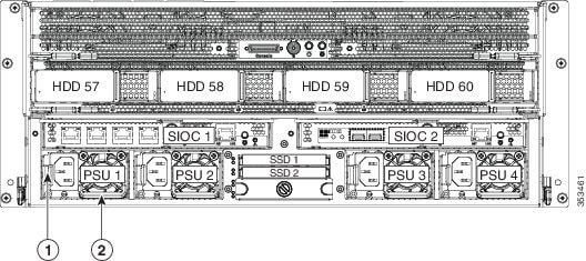
Replacing a Power Supply
The system can have two or four power supplies. When four power supplies are installed they are redundant as 2+2.
To replace or install a power supply, follow these steps:
Note![]() If you have ordered a system with power supply redundancy (four power supplies), you do not have to power off the system to replace up to two power supplies because they are redundant as 2+2.
If you have ordered a system with power supply redundancy (four power supplies), you do not have to power off the system to replace up to two power supplies because they are redundant as 2+2.
Step 1![]() Remove the power supply that you are replacing or a blank panel from an empty bay (see Figure 3-18):
Remove the power supply that you are replacing or a blank panel from an empty bay (see Figure 3-18):
a.![]() Perform one of the following actions:
Perform one of the following actions:
–![]() If your system has only two power supplies, shut down and power off the system as described in the “Shutting Down and Powering Off the System Chassis” section.
If your system has only two power supplies, shut down and power off the system as described in the “Shutting Down and Powering Off the System Chassis” section.
–![]() If your system has four power supplies, you do not have to power off the system.
If your system has four power supplies, you do not have to power off the system.
b.![]() Remove the power cord from the power supply that you are replacing.
Remove the power cord from the power supply that you are replacing.
c.![]() Grasp the power supply handle while pinching the release lever towards the handle.
Grasp the power supply handle while pinching the release lever towards the handle.
d.![]() Pull the power supply out of the bay.
Pull the power supply out of the bay.
Step 2![]() Install a new power supply:
Install a new power supply:
a.![]() Grasp the power supply handle and insert the new power supply into the empty bay.
Grasp the power supply handle and insert the new power supply into the empty bay.
b.![]() Push the power supply into the bay until the release lever locks.
Push the power supply into the bay until the release lever locks.
c.![]() Connect the power cord to the new power supply.
Connect the power cord to the new power supply.
d.![]() If you powered off the system, press and hold the system Power button for four seconds to return the system to main power mode.
If you powered off the system, press and hold the system Power button for four seconds to return the system to main power mode.
Figure 3-18 Removing and Replacing Power Supplies
|
|
|
Replacing DIMMs Inside the Server Node
The 16 DIMM sockets are inside the server node.
This section includes the following topics:
Note![]() To ensure the best system performance, it is important that you are familiar with memory performance guidelines and population rules before you install or replace the memory.
To ensure the best system performance, it is important that you are familiar with memory performance guidelines and population rules before you install or replace the memory.
DIMM Performance Guidelines and Population Rules
DIMM Sockets
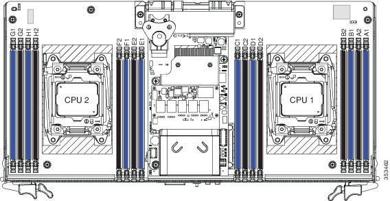
Figure 3-19 shows the DIMM sockets and how they are numbered on a server node board.
- A server node has 16 DDR3 DIMM sockets (8 for each CPU).
- Channels are labeled with letters as shown in Figure 3-19.
For example, channel A = DIMM sockets A1, A2.
Figure 3-19 DIMM Sockets and CPU Sockets on a Server Node Board
DIMM Population Rules
Observe the following guidelines when installing or replacing DIMMs:
- For optimal performance, spread DIMMs evenly across both CPUs and all channels.
- Populate the DIMM sockets of each CPU identically. Populate the blue DIMM 1 sockets first, then the black DIMM 2 slots. For example, populate the DIMM slots in this order:
1. A1, E1, B1, F1, C1, G1, D1, H1
2. A2, E2, B2, F2, C2, G2, D2, H2
- Observe the DIMM mixing rules shown in Table 3-5 .
Memory Mirroring Mode
When you enable memory mirroring mode, the memory subsystem simultaneously writes identical data to two channels. If a memory read from one of the channels returns incorrect data due to an uncorrectable memory error, the system automatically retrieves the data from the other channel. A transient or soft error in one channel does not affect the mirrored data, and operation continues.
Memory mirroring reduces the amount of memory available to the operating system by 50 percent because only one of the two populated channels provides data.
Lockstep Channel Mode
When you enable lockstep channel mode, each memory access is a 128-bit data access that spans four channels.
Lockstep channel mode requires that all four memory channels on a CPU must be populated identically with regards to size and organization. DIMM socket populations within a channel do not have to be identical but the same DIMM slot location across all four channels must be populated the same.
For example, DIMMs in sockets A1, B1, C1, and D1 must be identical. DIMMs in sockets A2, B2, C2, and D2 must be identical. However, the A1-B1-C1-D1 DIMMs do not have to be identical with the A2-B2-C2-D2 DIMMs.
DIMM Replacement Procedure
Note![]() You do not have to power off the chassis in this procedure. Replacement with chassis powered on is supported if you shut down the server node before removal.
You do not have to power off the chassis in this procedure. Replacement with chassis powered on is supported if you shut down the server node before removal.
Step 1![]() Shut down the server node by using the software interface or by pressing the node power button, as described in Shutting Down an Individual Server Node.
Shut down the server node by using the software interface or by pressing the node power button, as described in Shutting Down an Individual Server Node.
Step 2![]() Remove a server node from the system:
Remove a server node from the system:
a.![]() Grasp the two ejector levers and pinch their latches to release the levers (see Figure 3-15).
Grasp the two ejector levers and pinch their latches to release the levers (see Figure 3-15).
b.![]() Rotate both levers to the outside at the same time to evenly disengage the server node from its midplane connectors.
Rotate both levers to the outside at the same time to evenly disengage the server node from its midplane connectors.
c.![]() Pull the server node straight out from the system.
Pull the server node straight out from the system.
Step 3![]() Remove the server node cover as described in Removing the Server Node Cover.
Remove the server node cover as described in Removing the Server Node Cover.
Step 4![]() Locate the faulty DIMM and remove it from the socket on the riser by opening the ejector levers at both ends of the DIMM socket.
Locate the faulty DIMM and remove it from the socket on the riser by opening the ejector levers at both ends of the DIMM socket.
Note![]() Before installing DIMMs, refer to the population guidelines. See DIMM Performance Guidelines and Population Rules.
Before installing DIMMs, refer to the population guidelines. See DIMM Performance Guidelines and Population Rules.
a.![]() Align the new DIMM with the socket on the riser. Use the alignment key in the DIMM socket to correctly orient the DIMM.
Align the new DIMM with the socket on the riser. Use the alignment key in the DIMM socket to correctly orient the DIMM.
b.![]() Push the DIMM into the socket until it is fully seated and the ejector levers on either side of the socket lock into place.
Push the DIMM into the socket until it is fully seated and the ejector levers on either side of the socket lock into place.
Step 6![]() Replace the server node cover as described in Removing the Server Node Cover.
Replace the server node cover as described in Removing the Server Node Cover.
a.![]() With the two ejector levers open, align the new server node with the empty bay.
With the two ejector levers open, align the new server node with the empty bay.
Note![]() The server node must be in the top bay, as shown in Figure 1-2.
The server node must be in the top bay, as shown in Figure 1-2.
b.![]() Push the server node into the bay until it engages with the midplane connectors and is flush with the chassis.
Push the server node into the bay until it engages with the midplane connectors and is flush with the chassis.
c.![]() Rotate both ejector levers toward the center until they lay flat and their latches lock into the rear of the server node.
Rotate both ejector levers toward the center until they lay flat and their latches lock into the rear of the server node.
Step 8![]() Replace power cords and then power on the system by pressing and holding the power button on the front handle for four seconds.
Replace power cords and then power on the system by pressing and holding the power button on the front handle for four seconds.
Replacing CPUs and Heatsinks Inside the Server Node
The CPUs are inside the server node. Although CPUs are not spared separately for this server, you might need to move your CPUs from a faulty server node module to a new server node module.
CPU Configuration Rules
See Figure 3-19 for the CPU socket numbering.
CPU Replacement Procedure
Note![]() You do not have to power off the chassis in this procedure. Replacement with chassis powered on is supported if you shut down the server node before removal.
You do not have to power off the chassis in this procedure. Replacement with chassis powered on is supported if you shut down the server node before removal.
Step 1![]() Shut down the server node by using the software interface or by pressing the node power button, as described in Shutting Down an Individual Server Node.
Shut down the server node by using the software interface or by pressing the node power button, as described in Shutting Down an Individual Server Node.
Step 2![]() Remove a server node from the system:
Remove a server node from the system:
a.![]() Grasp the two ejector levers and pinch their latches to release the levers (see Figure 3-15).
Grasp the two ejector levers and pinch their latches to release the levers (see Figure 3-15).
b.![]() Rotate both levers to the outside at the same time to evenly disengage the server node from its midplane connectors.
Rotate both levers to the outside at the same time to evenly disengage the server node from its midplane connectors.
c.![]() Pull the server node straight out from the system.
Pull the server node straight out from the system.
Step 3![]() Remove the server node cover as described in Removing the Server Node Cover.
Remove the server node cover as described in Removing the Server Node Cover.
Step 4![]() Use a Number 2 Phillips-head screwdriver to loosen the four captive screws that secure the heatsink, and then lift it off of the CPU.
Use a Number 2 Phillips-head screwdriver to loosen the four captive screws that secure the heatsink, and then lift it off of the CPU.
Note![]() Loosen each screw evenly to avoid damaging the heatsink or CPU.
Loosen each screw evenly to avoid damaging the heatsink or CPU.
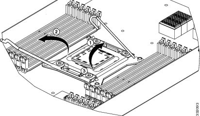
Step 5![]() Unclip the first CPU retaining latch that is labeled with the
Unclip the first CPU retaining latch that is labeled with the  icon, and then unclip the second retaining latch that is labeled with the
  icon. See Figure 3-20.
Note![]() You must hold the first retaining latch open before you can lift the second retaining latch.
You must hold the first retaining latch open before you can lift the second retaining latch.
Step 6![]() Open the hinged CPU cover plate. See Figure 3-20.
Open the hinged CPU cover plate. See Figure 3-20.
Figure 3-20 CPU Socket Retaining Latches
|
|
|
||
|
|
|
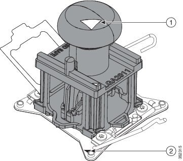
a.![]() Set the Pick-and-Place tool on the CPU in the socket, aligning the arrow on the tool with the registration mark on the socket (the small triangular mark). See Figure 3-21.
Set the Pick-and-Place tool on the CPU in the socket, aligning the arrow on the tool with the registration mark on the socket (the small triangular mark). See Figure 3-21.
b.![]() Press the top button on the tool to grasp the installed CPU.
Press the top button on the tool to grasp the installed CPU.
c.![]() Lift the tool and CPU straight up.
Lift the tool and CPU straight up.
d.![]() Press the top button on the tool to release the old CPU on an antistatic surface.
Press the top button on the tool to release the old CPU on an antistatic surface.
Figure 3-21 Pick-and-Place Tool
|
|
|
Step 8![]() Insert the new CPU into the Pick-and-Place tool:
Insert the new CPU into the Pick-and-Place tool:
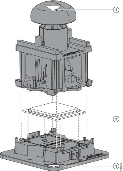
a.![]() Remove the new CPU from the packaging and place it on the pedestal that is included in the kit. Align the registration mark on the corner of the CPU with the arrow on the corner of the pedestal (see Figure 3-22).
Remove the new CPU from the packaging and place it on the pedestal that is included in the kit. Align the registration mark on the corner of the CPU with the arrow on the corner of the pedestal (see Figure 3-22).
b.![]() Press down on the top button of the tool to lock it open.
Press down on the top button of the tool to lock it open.
c.![]() Set the Pick-and-Place tool on the CPU pedestal, aligning the arrow on the tool with the arrow on the corner of the pedestal. Make sure that the tabs on the tool are fully seated in the slots on the pedestal.
Set the Pick-and-Place tool on the CPU pedestal, aligning the arrow on the tool with the arrow on the corner of the pedestal. Make sure that the tabs on the tool are fully seated in the slots on the pedestal.
d.![]() Press the side lever on the tool to grasp and lock in the CPU.
Press the side lever on the tool to grasp and lock in the CPU.
e.![]() Lift the tool and CPU straight up off the pedestal.
Lift the tool and CPU straight up off the pedestal.
Figure 3-22 CPU and Pick-and-Place Tool on Pedestal
|
|
|
a.![]() Set the Pick-and-Place tool that is holding the CPU over the empty CPU socket on the motherboard.
Set the Pick-and-Place tool that is holding the CPU over the empty CPU socket on the motherboard.
Note![]() Align the arrow on the top of the tool with the registration mark (small triangle) that is stamped on the metal of the CPU socket, as shown in Figure 3-21.
Align the arrow on the top of the tool with the registration mark (small triangle) that is stamped on the metal of the CPU socket, as shown in Figure 3-21.
b.![]() Press the top button on the tool to set the CPU into the socket. Remove the empty tool.
Press the top button on the tool to set the CPU into the socket. Remove the empty tool.
c.![]() Close the hinged CPU cover plate.
Close the hinged CPU cover plate.
d.![]() Clip down the CPU retaining latch with the icon first, then clip down the CPU retaining latch with the icon. See Figure 3-20.
Clip down the CPU retaining latch with the icon first, then clip down the CPU retaining latch with the icon. See Figure 3-20.
a.![]() Apply an alcohol-based cleaning solution to the old thermal grease and let it soak for a least 15 seconds.
Apply an alcohol-based cleaning solution to the old thermal grease and let it soak for a least 15 seconds.
b.![]() Wipe all of the old thermal grease off the old heatsink using a soft cloth that will not scratch the heatsink surface.
Wipe all of the old thermal grease off the old heatsink using a soft cloth that will not scratch the heatsink surface.
c.![]() Apply thermal grease from the syringe that is included with the new CPU to the top of the CPU.
Apply thermal grease from the syringe that is included with the new CPU to the top of the CPU.
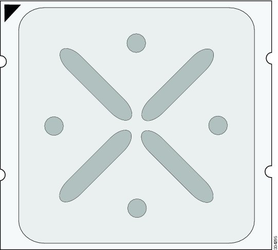
Apply about half the syringe contents to the top of the CPU in the pattern that is shown in Figure 3-23.
Note![]() If you do not have a syringe of thermal grease, you can order a spare
If you do not have a syringe of thermal grease, you can order a spare
(Cisco PID UCS-CPU-GREASE3).
Figure 3-23 Thermal Grease Application Pattern
d.![]() Align the heatsink captive screws with the motherboard standoffs, and then use a Number 2 Phillips-head screwdriver to tighten the captive screws evenly.
Align the heatsink captive screws with the motherboard standoffs, and then use a Number 2 Phillips-head screwdriver to tighten the captive screws evenly.
Note![]() Alternate tightening each screw evenly to avoid damaging the heatsink or CPU.
Alternate tightening each screw evenly to avoid damaging the heatsink or CPU.
Step 11![]() Replace the server node cover as described in Removing the Server Node Cover.
Replace the server node cover as described in Removing the Server Node Cover.
Step 12![]() Install a server node:
Install a server node:
a.![]() With the two ejector levers open, align the new server node with the empty bay.
With the two ejector levers open, align the new server node with the empty bay.
Note![]() The server node must be in the top bay, as shown in Figure 1-2.
The server node must be in the top bay, as shown in Figure 1-2.
b.![]() Push the server node into the bay until it engages with the midplane connectors and is flush with the chassis.
Push the server node into the bay until it engages with the midplane connectors and is flush with the chassis.
c.![]() Rotate both ejector levers toward the center until they lay flat and their latches lock into the rear of the server node.
Rotate both ejector levers toward the center until they lay flat and their latches lock into the rear of the server node.
Step 13![]() Replace power cords and then power on the system by pressing and holding the power button on the front handle for four seconds.
Replace power cords and then power on the system by pressing and holding the power button on the front handle for four seconds.
Additional CPU-Related Parts To Order With RMA Replacement Server Nodes
When a return material authorization (RMA) of the server node or CPU is done on a system, there are additional parts that might not be included with the CPU or motherboard spare bill of materials (BOM). The TAC engineer might need to add the additional parts to the RMA to help ensure a successful replacement.
–![]() Heat sink cleaning kit (UCSX-HSCK=)
Heat sink cleaning kit (UCSX-HSCK=)
–![]() Thermal grease kit for C3160 (UCS-CPU-GREASE3=)
Thermal grease kit for C3160 (UCS-CPU-GREASE3=)
–![]() Intel CPU Pick-n-Place tool for EP CPUs (UCS-CPU-EP-PNP=)
Intel CPU Pick-n-Place tool for EP CPUs (UCS-CPU-EP-PNP=)
–![]() Heat sink cleaning kit (UCSX-HSCK=)
Heat sink cleaning kit (UCSX-HSCK=)
–![]() Intel CPU Pick-n-Place tool for EP CPUs (UCS-CPU-EP-PNP=)
Intel CPU Pick-n-Place tool for EP CPUs (UCS-CPU-EP-PNP=)
A CPU heatsink cleaning kit is good for up to four CPU and heatsink cleanings. The cleaning kit contains two bottles of solution, one to clean the CPU and heatsink of old thermal interface material and the other to prepare the surface of the heatsink.
It is important to clean the old thermal interface material off of the CPU prior to installing the heatsinks. Therefore, when ordering new heatsinks it is still necessary to order the heatsink cleaning kit at a minimum.
Replacing a RAID Controller Card Inside the Server Node
The Cisco modular RAID controller card connects to a mezzanine-style socket inside the server node. The SuperCap power module (SCPM) comes already attached to a new card, so you do not have to remove that separately.
RAID Card Firmware Compatibility
Firmware on the RAID controller must be verified for compatibility with the current Cisco IMC and BIOS versions that are installed on the server. If not compatible, upgrade or downgrade the RAID controller firmware accordingly using the Host Upgrade Utility (HUU) for your firmware release to bring it to a compatible level.
See the HUU guide for your Cisco IMC release for instructions on downloading and using the utility to bring server components to compatible levels: HUU Guides
Replacement Procedure
Note![]() You do not have to power off the chassis in this procedure. Replacement with chassis powered on is supported if you shut down the server node before removal.
You do not have to power off the chassis in this procedure. Replacement with chassis powered on is supported if you shut down the server node before removal.
Step 1![]() Shut down the server node by using the software interface or by pressing the node power button, as described in Shutting Down an Individual Server Node.
Shut down the server node by using the software interface or by pressing the node power button, as described in Shutting Down an Individual Server Node.
Step 2![]() Remove a server node from the system:
Remove a server node from the system:
a.![]() Grasp the two ejector levers and pinch their latches to release the levers (see Figure 3-15).
Grasp the two ejector levers and pinch their latches to release the levers (see Figure 3-15).
b.![]() Rotate both levers to the outside at the same time to evenly disengage the server node from its midplane connectors.
Rotate both levers to the outside at the same time to evenly disengage the server node from its midplane connectors.
c.![]() Pull the server node straight out from the system.
Pull the server node straight out from the system.
Step 3![]() Remove the server node cover as described in Removing the Server Node Cover.
Remove the server node cover as described in Removing the Server Node Cover.
Step 4![]() Remove a Cisco modular RAID controller card:
Remove a Cisco modular RAID controller card:
a.![]() Loosen the two captive thumbscrews that secure the card to the board (see Figure 3-24).
Loosen the two captive thumbscrews that secure the card to the board (see Figure 3-24).
b.![]() Grasp the card at both ends and lift it evenly to disengage the connector on the underside of the card from the mezzanine socket.
Grasp the card at both ends and lift it evenly to disengage the connector on the underside of the card from the mezzanine socket.
Step 5![]() Install a Cisco modular RAID controller card:
Install a Cisco modular RAID controller card:
a.![]() Align the card and bracket over the mezzanine socket and the three standoffs.
Align the card and bracket over the mezzanine socket and the three standoffs.
b.![]() Press down on both ends of the card to engage the connector on the underside of the card with the mezzanine socket.
Press down on both ends of the card to engage the connector on the underside of the card with the mezzanine socket.
c.![]() Install the screw that passes through the supercap power module (backup battery) cover.
Install the screw that passes through the supercap power module (backup battery) cover.
Step 6![]() Install the heat sink assembly to the controller card:
Install the heat sink assembly to the controller card:
a.![]() Remove the protective tape from the thermal interface that is on the underside of the heatsink.
Remove the protective tape from the thermal interface that is on the underside of the heatsink.
b.![]() Align the heat sink assembly and its two captive screws with the holes in the controller card.
Align the heat sink assembly and its two captive screws with the holes in the controller card.
c.![]() Tighten the two captive screws to the two standoffs that are under the controller card.
Tighten the two captive screws to the two standoffs that are under the controller card.
Step 7![]() Replace the server node cover as described in Removing the Server Node Cover.
Replace the server node cover as described in Removing the Server Node Cover.
a.![]() With the two ejector levers open, align the new server node with the empty bay.
With the two ejector levers open, align the new server node with the empty bay.
Note![]() The server node must be in the top bay, as shown in Figure 1-2.
The server node must be in the top bay, as shown in Figure 1-2.
b.![]() Push the server node into the bay until it engages with the midplane connectors and is flush with the chassis.
Push the server node into the bay until it engages with the midplane connectors and is flush with the chassis.
c.![]() Rotate both ejector levers toward the center until they lay flat and their latches lock into the rear of the server node.
Rotate both ejector levers toward the center until they lay flat and their latches lock into the rear of the server node.
Step 9![]() Replace power cords and then power on the system by pressing and holding the power button on the front handle for four seconds.
Replace power cords and then power on the system by pressing and holding the power button on the front handle for four seconds.
Step 10![]() See Restoring RAID Configuration After Replacing a RAID Controller to restore your RAID configuration.
See Restoring RAID Configuration After Replacing a RAID Controller to restore your RAID configuration.
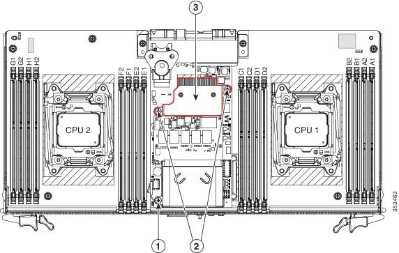
Figure 3-24 Cisco Modular RAID Controller Card Inside the Server Node
|
|
Screw that passes through supercap power module cover to standoff |
|
|
|
|
Two captive screws that pass through heatsink assembly to standoffs |
|
Replacing an RTC Battery Inside the Server Node
The real-time clock (RTC) battery retains system settings when the server is disconnected from power. The battery type is CR2032. Cisco supports the industry-standard CR2032 battery, which can be purchased from most electronic stores.
Note![]() When the RTC battery is removed or it completely loses power, settings that were stored in the BMC of the server node are lost. You must reconfigure the BMC settings after installing a new battery.
When the RTC battery is removed or it completely loses power, settings that were stored in the BMC of the server node are lost. You must reconfigure the BMC settings after installing a new battery.
Note![]() You do not have to power off the chassis in this procedure. Replacement with chassis powered on is supported if you shut down the server node before removal.
You do not have to power off the chassis in this procedure. Replacement with chassis powered on is supported if you shut down the server node before removal.
Step 1![]() Shut down the server node by using the software interface or by pressing the node power button, as described in Shutting Down an Individual Server Node.
Shut down the server node by using the software interface or by pressing the node power button, as described in Shutting Down an Individual Server Node.
Step 2![]() Remove a server node from the system:
Remove a server node from the system:
a.![]() Grasp the two ejector levers and pinch their latches to release the levers (see Figure 3-15).
Grasp the two ejector levers and pinch their latches to release the levers (see Figure 3-15).
b.![]() Rotate both levers to the outside at the same time to evenly disengage the server node from its midplane connectors.
Rotate both levers to the outside at the same time to evenly disengage the server node from its midplane connectors.
c.![]() Pull the server node straight out from the system.
Pull the server node straight out from the system.
Note![]() You do not have to remove the server node cover to access the RTC battery.
You do not have to remove the server node cover to access the RTC battery.
Step 3![]() Remove the server node RTC battery:
Remove the server node RTC battery:
a.![]() Locate the RTC battery. See Figure 3-25.
Locate the RTC battery. See Figure 3-25.
b.![]() Bend the battery retaining clip away from the battery and pull the battery from the socket.
Bend the battery retaining clip away from the battery and pull the battery from the socket.
Step 4![]() Install the RTC battery:
Install the RTC battery:
a.![]() Bend the retaining clip away from the battery socket and insert the battery in the socket.
Bend the retaining clip away from the battery socket and insert the battery in the socket.
Note![]() The flat, positive side of the battery marked “+” should face the retaining clip.
The flat, positive side of the battery marked “+” should face the retaining clip.
b.![]() Push the battery into the socket until it is fully seated and the retaining clip clicks over the top of the battery.
Push the battery into the socket until it is fully seated and the retaining clip clicks over the top of the battery.
a.![]() With the two ejector levers open, align the new server node with the empty bay.
With the two ejector levers open, align the new server node with the empty bay.
Note![]() The server node must be in the top bay, as shown in Figure 1-2.
The server node must be in the top bay, as shown in Figure 1-2.
b.![]() Push the server node into the bay until it engages with the midplane connectors and is flush with the chassis.
Push the server node into the bay until it engages with the midplane connectors and is flush with the chassis.
c.![]() Rotate both ejector levers toward the center until they lay flat and their latches lock into the rear of the server node.
Rotate both ejector levers toward the center until they lay flat and their latches lock into the rear of the server node.
Step 6![]() Replace power cords and then power on the system by pressing and holding the power button on the front handle for four seconds.
Replace power cords and then power on the system by pressing and holding the power button on the front handle for four seconds.
Step 7![]() Reconfigure the settings in the BMC of this node.
Reconfigure the settings in the BMC of this node.
Figure 3-25 Location of the Server Node RTC Battery and USB Port
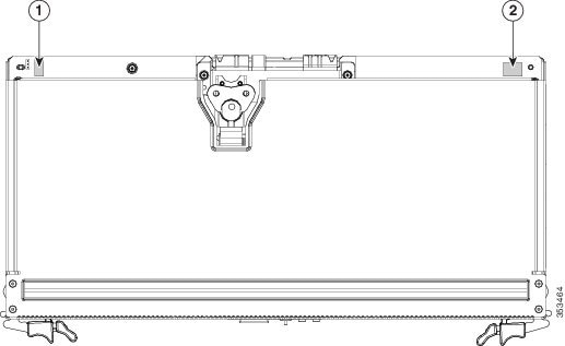
|
|
|
Replacing an Internal USB Drive Inside the Server Node
Internal USB Drive Replacement Procedure
Note![]() You do not have to power off the chassis in this procedure. Replacement with chassis powered on is supported if you shut down the server node before removal.
You do not have to power off the chassis in this procedure. Replacement with chassis powered on is supported if you shut down the server node before removal.
Step 1![]() Shut down the server node by using the software interface or by pressing the node power button, as described in Shutting Down an Individual Server Node.
Shut down the server node by using the software interface or by pressing the node power button, as described in Shutting Down an Individual Server Node.
Step 2![]() Remove a server node from the system:
Remove a server node from the system:
a.![]() Grasp the two ejector levers and pinch their latches to release the levers (see Figure 3-15).
Grasp the two ejector levers and pinch their latches to release the levers (see Figure 3-15).
b.![]() Rotate both levers to the outside at the same time to evenly disengage the server node from its midplane connectors.
Rotate both levers to the outside at the same time to evenly disengage the server node from its midplane connectors.
c.![]() Pull the server node straight out from the system.
Pull the server node straight out from the system.
Note![]() You do not have to remove the server node cover to access the USB port.
You do not have to remove the server node cover to access the USB port.
Step 3![]() Remove an existing USB flash drive from the port on the server node board. Pull the drive horizontally from the port.
Remove an existing USB flash drive from the port on the server node board. Pull the drive horizontally from the port.
Step 4![]() Install a USB flash drive. Insert the new USB flash drive into the horizontal socket on the server node board.
Install a USB flash drive. Insert the new USB flash drive into the horizontal socket on the server node board.
a.![]() With the two ejector levers open, align the new server node with the empty bay.
With the two ejector levers open, align the new server node with the empty bay.
Note![]() The server node must be in the top bay, as shown in Figure 1-2.
The server node must be in the top bay, as shown in Figure 1-2.
b.![]() Push the server node into the bay until it engages with the midplane connectors and is flush with the chassis.
Push the server node into the bay until it engages with the midplane connectors and is flush with the chassis.
c.![]() Rotate both ejector levers toward the center until they lay flat and their latches lock into the rear of the server node.
Rotate both ejector levers toward the center until they lay flat and their latches lock into the rear of the server node.
Step 6![]() Replace power cords and then power on the system by pressing and holding the power button on the front handle for four seconds.
Replace power cords and then power on the system by pressing and holding the power button on the front handle for four seconds.
Enabling or Disabling the Internal USB Port
The factory default is for all USB ports on the system to be enabled. However, the internal USB port can be enabled or disabled in the system BIOS. To enable or disable the internal USB port, follow these steps:
Step 1![]() Enter the BIOS Setup utility by pressing the F2 key when prompted during bootup.
Enter the BIOS Setup utility by pressing the F2 key when prompted during bootup.
Step 2![]() Navigate to the Advanced tab.
Navigate to the Advanced tab.
Step 3![]() On the Advanced tab, select USB Configuration.
On the Advanced tab, select USB Configuration.
Step 4![]() On the USB Configuration page, select USB Ports Configuration.
On the USB Configuration page, select USB Ports Configuration.
Step 5![]() Scroll to USB Port: Internal, press Enter, and then select either Enabled or Disabled from the menu.
Scroll to USB Port: Internal, press Enter, and then select either Enabled or Disabled from the menu.
Step 6![]() Press F10 to save and exit the utility.
Press F10 to save and exit the utility.
Installing a Trusted Platform Module (TPM) Inside the Server Node
The trusted platform module (TPM) is a small circuit board that attaches to a socket on the server node board. This section contains the following procedures, which must be followed in this order when installing and enabling a TPM:
1.![]() Installing the TPM Hardware
Installing the TPM Hardware
Installing the TPM Hardware
Note![]() For security purposes, the TPM is installed with a one-way screw. It cannot be removed with a standard screwdriver.
For security purposes, the TPM is installed with a one-way screw. It cannot be removed with a standard screwdriver.
Note![]() You do not have to power off the chassis in this procedure. Replacement with chassis powered on is supported if you shut down the server node before removal.
You do not have to power off the chassis in this procedure. Replacement with chassis powered on is supported if you shut down the server node before removal.
Step 1![]() Shut down the server node by using the software interface or by pressing the node power button, as described in Shutting Down an Individual Server Node.
Shut down the server node by using the software interface or by pressing the node power button, as described in Shutting Down an Individual Server Node.
Step 2![]() Remove a server node from the system:
Remove a server node from the system:
a.![]() Grasp the two ejector levers and pinch their latches to release the levers (see Figure 3-15).
Grasp the two ejector levers and pinch their latches to release the levers (see Figure 3-15).
b.![]() Rotate both levers to the outside at the same time to evenly disengage the server node from its midplane connectors.
Rotate both levers to the outside at the same time to evenly disengage the server node from its midplane connectors.
c.![]() Pull the server node straight out from the system.
Pull the server node straight out from the system.
Note![]() You do not have to remove the server node cover to access the TPM socket.
You do not have to remove the server node cover to access the TPM socket.
a.![]() Locate the TPM socket on the server node board, as shown in Figure 3-26.
Locate the TPM socket on the server node board, as shown in Figure 3-26.
b.![]() Align the connector that is on the bottom of the TPM circuit board with the TPM socket. Align the screw hole on the TPM board with the screw hole adjacent to the TPM socket.
Align the connector that is on the bottom of the TPM circuit board with the TPM socket. Align the screw hole on the TPM board with the screw hole adjacent to the TPM socket.
c.![]() Push down evenly on the TPM to seat it in the motherboard socket.
Push down evenly on the TPM to seat it in the motherboard socket.
d.![]() Install the single one-way screw that secures the TPM to the motherboard.
Install the single one-way screw that secures the TPM to the motherboard.
a.![]() With the two ejector levers open, align the new server node with the empty bay.
With the two ejector levers open, align the new server node with the empty bay.
Note![]() The server node must be in the top bay, as shown in Figure 1-2.
The server node must be in the top bay, as shown in Figure 1-2.
b.![]() Push the server node into the bay until it engages with the midplane connectors and is flush with the chassis.
Push the server node into the bay until it engages with the midplane connectors and is flush with the chassis.
c.![]() Rotate both ejector levers toward the center until they lay flat and their latches lock into the rear of the server node.
Rotate both ejector levers toward the center until they lay flat and their latches lock into the rear of the server node.
Step 5![]() Replace power cords and then power on the system by pressing and holding the power button on the front handle for four seconds.
Replace power cords and then power on the system by pressing and holding the power button on the front handle for four seconds.
Step 6![]() Continue with Enabling TPM Support in the BIOS.
Continue with Enabling TPM Support in the BIOS.
Figure 3-26 TPM Socket Location on the Server Node Board
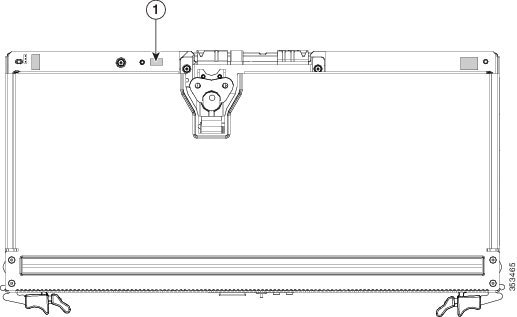
|
|
|
Enabling TPM Support in the BIOS
Note![]() After hardware installation, you must enable TPM support in the BIOS.
After hardware installation, you must enable TPM support in the BIOS.
Note![]() You must set a BIOS Administrator password before performing this procedure. To set this password, press the F2 key when prompted during system boot to enter the BIOS Setup utility. Then navigate to Security > Set Administrator Password and enter the new password twice as prompted.
You must set a BIOS Administrator password before performing this procedure. To set this password, press the F2 key when prompted during system boot to enter the BIOS Setup utility. Then navigate to Security > Set Administrator Password and enter the new password twice as prompted.
a.![]() Watch during bootup for the F2 prompt, and then press F2 to enter BIOS setup.
Watch during bootup for the F2 prompt, and then press F2 to enter BIOS setup.
b.![]() Log in to the BIOS Setup Utility with your BIOS Administrator password.
Log in to the BIOS Setup Utility with your BIOS Administrator password.
c.![]() On the BIOS Setup Utility window, choose the Advanced tab.
On the BIOS Setup Utility window, choose the Advanced tab.
d.![]() Choose Trusted Computing to open the TPM Security Device Configuration window.
Choose Trusted Computing to open the TPM Security Device Configuration window.
e.![]() Change TPM SUPPORT to Enabled.
Change TPM SUPPORT to Enabled.
f.![]() Press F10 to save your settings and reboot the server.
Press F10 to save your settings and reboot the server.
Step 2![]() Verify that TPM support is now enabled:
Verify that TPM support is now enabled:
a.![]() Watch during bootup for the F2 prompt, and then press F2 to enter BIOS setup.
Watch during bootup for the F2 prompt, and then press F2 to enter BIOS setup.
b.![]() Log into the BIOS Setup utility with your BIOS Administrator password.
Log into the BIOS Setup utility with your BIOS Administrator password.
d.![]() Choose Trusted Computing to open the TPM Security Device Configuration window.
Choose Trusted Computing to open the TPM Security Device Configuration window.
e.![]() Verify that TPM SUPPORT and TPM State are Enabled.
Verify that TPM SUPPORT and TPM State are Enabled.
Step 3![]() Continue with Enabling the Intel TXT Feature in the BIOS.
Continue with Enabling the Intel TXT Feature in the BIOS.
Enabling the Intel TXT Feature in the BIOS
Intel Trusted Execution Technology (TXT) provides greater protection for information that is used and stored on the business server. A key aspect of that protection is the provision of an isolated execution environment and associated sections of memory where operations can be conducted on sensitive data, invisibly to the rest of the system. Intel TXT provides for a sealed portion of storage where sensitive data such as encryption keys can be kept, helping to shield them from being compromised during an attack by malicious code.
Step 1![]() Reboot the server and watch for the prompt to press F2.
Reboot the server and watch for the prompt to press F2.
Step 2![]() When prompted, press F2 to enter the BIOS Setup utility.
When prompted, press F2 to enter the BIOS Setup utility.
Step 3![]() Verify that the prerequisite BIOS values are enabled:
Verify that the prerequisite BIOS values are enabled:
b.![]() Choose Intel TXT(LT-SX) Configuration to open the Intel TXT(LT-SX) Hardware Support window.
Choose Intel TXT(LT-SX) Configuration to open the Intel TXT(LT-SX) Hardware Support window.
c.![]() Verify that the following items are listed as Enabled:
Verify that the following items are listed as Enabled:
–![]() VT-d Support (default is Enabled)
VT-d Support (default is Enabled)
–![]() VT Support (default is Enabled)
VT Support (default is Enabled)
- If VT-d Support and VT Support are already enabled, skip to Step 4.
- If VT-d Support and VT Support are not enabled, continue with the next steps to enable them.
d.![]() Press Escape to return to the BIOS Setup utility Advanced tab.
Press Escape to return to the BIOS Setup utility Advanced tab.
e.![]() On the Advanced tab, choose Processor Configuration to open the Processor Configuration window.
On the Advanced tab, choose Processor Configuration to open the Processor Configuration window.
f.![]() Set Intel (R) VT and Intel (R) VT-d to Enabled.
Set Intel (R) VT and Intel (R) VT-d to Enabled.
Step 4![]() Enable the Intel Trusted Execution Technology (TXT) feature:
Enable the Intel Trusted Execution Technology (TXT) feature:
a.![]() Return to the Intel TXT(LT-SX) Hardware Support window if you are not already there.
Return to the Intel TXT(LT-SX) Hardware Support window if you are not already there.
b.![]() Set TXT Support to Enabled.
Set TXT Support to Enabled.
Step 5![]() Press F10 to save your changes and exit the BIOS Setup utility.
Press F10 to save your changes and exit the BIOS Setup utility.
Replacing an Adapter Card Inside the SIOC
The adapter card inside the system I/O controller (SIOC) provides rear-panel connectivity to the system.
You can have two different types of adapter card in the same system.
Step 1![]() Shut down and remove power from the entire system, as described in Shutting Down and Powering Off the System Chassis.
Shut down and remove power from the entire system, as described in Shutting Down and Powering Off the System Chassis.
Step 2![]() Remove the SIOC from the system:
Remove the SIOC from the system:
a.![]() Loosen the single captive thumbscrew on the SIOC and then open its two hinged ejector levers to evenly disengage the SIOC from its midplane connector.
Loosen the single captive thumbscrew on the SIOC and then open its two hinged ejector levers to evenly disengage the SIOC from its midplane connector.
b.![]() Pull the SIOC from the system.
Pull the SIOC from the system.
Step 3![]() Remove the SIOC cover as described in Removing the System I/O Controller Cover.
Remove the SIOC cover as described in Removing the System I/O Controller Cover.
Step 4![]() Remove an existing adapter card:
Remove an existing adapter card:
a.![]() Loosen the single captive thumbscrew that secures the adapter card to the SIOC.
Loosen the single captive thumbscrew that secures the adapter card to the SIOC.
b.![]() Slide the adapter card horizontally to disengage it from its socket on the SIOC board.
Slide the adapter card horizontally to disengage it from its socket on the SIOC board.
c.![]() Lift the adapter card up and out of the SIOC.
Lift the adapter card up and out of the SIOC.
Step 5![]() Install a new adapter card:
Install a new adapter card:
a.![]() Set the new adapter card on the floor of the SIOC so that its connector edge is aligned with the socket and the thumbscrew is facing up.
Set the new adapter card on the floor of the SIOC so that its connector edge is aligned with the socket and the thumbscrew is facing up.
b.![]() Slide the adapter card horizontally to fully engage its connector edge with the socket.
Slide the adapter card horizontally to fully engage its connector edge with the socket.
c.![]() Tighten the captive thumbscrew on the adapter card to secure it to the SIOC.
Tighten the captive thumbscrew on the adapter card to secure it to the SIOC.
Step 6![]() Replace the cover to the SIOC.
Replace the cover to the SIOC.
Step 7![]() Replace the SIOC to the system:
Replace the SIOC to the system:
Note![]() If you have only one SIOC, it must be in SIOC bay 1 (see Figure 1-2).
If you have only one SIOC, it must be in SIOC bay 1 (see Figure 1-2).
a.![]() Push the SIOC into its bay until it stops against the internal midplane.
Push the SIOC into its bay until it stops against the internal midplane.
b.![]() Close the two levers on the SIOC to fully engage the SIOC connector with its backplane.
Close the two levers on the SIOC to fully engage the SIOC connector with its backplane.
c.![]() Tighten the thumbscrew on the SIOC levers.
Tighten the thumbscrew on the SIOC levers.
Step 8![]() Replace power cords and then power on the system by pressing and holding the power button on the front handle for four seconds.
Replace power cords and then power on the system by pressing and holding the power button on the front handle for four seconds.
Figure 3-27 Replacing an Adapter Card Inside the SIOC
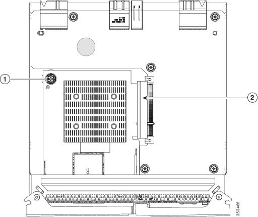
|
|
|
Special Considerations for Cisco UCS Virtual Interface Cards
Table 3-6 describes the considerations for the supported Cisco UCS virtual interface cards (VICs) that install to the SIOC adapter card socket.
Note![]() The Cisco UCS VIC 1227 (UCSC-MLOM-CSC-02) is not compatible to use in Cisco Card NIC mode with a certain Cisco SFP+ module. Do not use a Cisco SFP+ module part number 37-0961-01 that has a serial number in the range MOC1238xxxx to MOC1309xxxx. If you use the Cisco UCS VIC 1227 in Cisco Card NIC mode, use a different part number Cisco SFP+ module, or you can use this part number 37-0961-01 if the serial number is not included in the range above. See the data sheet for this adapter for other supported SFP+ modules: Cisco UCS VIC 1227 Data Sheet
The Cisco UCS VIC 1227 (UCSC-MLOM-CSC-02) is not compatible to use in Cisco Card NIC mode with a certain Cisco SFP+ module. Do not use a Cisco SFP+ module part number 37-0961-01 that has a serial number in the range MOC1238xxxx to MOC1309xxxx. If you use the Cisco UCS VIC 1227 in Cisco Card NIC mode, use a different part number Cisco SFP+ module, or you can use this part number 37-0961-01 if the serial number is not included in the range above. See the data sheet for this adapter for other supported SFP+ modules: Cisco UCS VIC 1227 Data Sheet
Replacing an RTC Battery Inside the SIOC
The real-time clock (RTC) battery retains settings when the SIOC is disconnected from power. The battery type in the SIOC is CR1632. Cisco supports the industry-standard CR1632 battery, which can be purchased from most electronic stores.
Note![]() When the RTC battery is removed or it completely loses power, settings that were stored in the CMC of the SIOC are lost. You must reconfigure the CMC settings after installing a new battery.
When the RTC battery is removed or it completely loses power, settings that were stored in the CMC of the SIOC are lost. You must reconfigure the CMC settings after installing a new battery.
Step 1![]() Shut down and remove power from the entire system, as described in Shutting Down and Powering Off the System Chassis.
Shut down and remove power from the entire system, as described in Shutting Down and Powering Off the System Chassis.
Step 2![]() Remove the SIOC from the system:
Remove the SIOC from the system:
a.![]() Loosen the single captive thumbscrew on the SIOC and then open its two hinged ejector levers to evenly disengage the SIOC from its midplane connector.
Loosen the single captive thumbscrew on the SIOC and then open its two hinged ejector levers to evenly disengage the SIOC from its midplane connector.
b.![]() Pull the SIOC from the system.
Pull the SIOC from the system.
Step 3![]() Remove the SIOC cover as described in Removing the System I/O Controller Cover.
Remove the SIOC cover as described in Removing the System I/O Controller Cover.
Step 4![]() Gently pry under the battery to lift it from its socket on the SIOC board.
Gently pry under the battery to lift it from its socket on the SIOC board.
Step 5![]() Insert the new battery into the socket and then press down until it sits flat.
Insert the new battery into the socket and then press down until it sits flat.
Step 6![]() Replace the cover to the SIOC.
Replace the cover to the SIOC.
Step 7![]() Replace the SIOC to the system:
Replace the SIOC to the system:
Note![]() If you have only one SIOC, it must be in SIOC bay 1 (see Figure 1-2).
If you have only one SIOC, it must be in SIOC bay 1 (see Figure 1-2).
a.![]() Push the SIOC into its bay until it stops against the internal midplane.
Push the SIOC into its bay until it stops against the internal midplane.
b.![]() Close the two levers on the SIOC to fully engage the SIOC connector with its backplane.
Close the two levers on the SIOC to fully engage the SIOC connector with its backplane.
c.![]() Tighten the thumbscrew on the SIOC levers.
Tighten the thumbscrew on the SIOC levers.
Step 8![]() Replace power cords and then power on the system by pressing and holding the power button on the front handle for four seconds.
Replace power cords and then power on the system by pressing and holding the power button on the front handle for four seconds.
Step 9![]() Reconfigure the settings in the CMC for this SIOC.
Reconfigure the settings in the CMC for this SIOC.
Figure 3-28 Replacing an RTC Battery Inside the SIOC
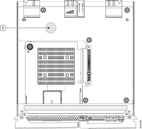
|
|
|
Service Headers on the Server Node Board
The server node board includes headers that you can jumper for certain service functions.
This section includes the following topics:
- Service Header Locations on the Server Node Board
- Using the Clear Password Header P11
- Using the Clear CMOS Header P13
Service Header Locations on the Server Node Board
There are two supported, three-pin service headers on the server node board. See Figure 3-29 for the locations.
Figure 3-29 Service Headers on the Server Node Board
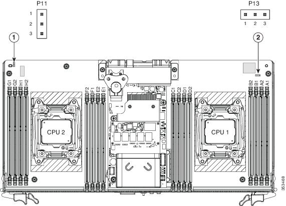
|
|
|
Using the Clear Password Header P11
You can use a jumper on header P11 to clear the administrator password.
Note![]() You do not have to power off the chassis in this procedure. Replacement with chassis powered on is supported if you shut down the server node before removal.
You do not have to power off the chassis in this procedure. Replacement with chassis powered on is supported if you shut down the server node before removal.
Step 1![]() Shut down the server node by using the software interface or by pressing the node power button, as described in Shutting Down an Individual Server Node.
Shut down the server node by using the software interface or by pressing the node power button, as described in Shutting Down an Individual Server Node.
Step 2![]() Remove a server node from the system:
Remove a server node from the system:
a.![]() Grasp the two ejector levers and pinch their latches to release the levers (see Figure 3-15).
Grasp the two ejector levers and pinch their latches to release the levers (see Figure 3-15).
b.![]() Rotate both levers to the outside at the same time to evenly disengage the server node from its midplane connectors.
Rotate both levers to the outside at the same time to evenly disengage the server node from its midplane connectors.
c.![]() Pull the server node straight out from the system.
Pull the server node straight out from the system.
Note![]() You do not have to remove the server node cover to access the header.
You do not have to remove the server node cover to access the header.
Step 3![]() Remove the server node cover as described in Removing the Server Node Cover.
Remove the server node cover as described in Removing the Server Node Cover.
Step 4![]() Locate header P11 (see Figure 3-29).
Locate header P11 (see Figure 3-29).
Step 5![]() Install a jumper to pins 2 and 3 of the header.
Install a jumper to pins 2 and 3 of the header.
Step 6![]() Install the server node:
Install the server node:
a.![]() With the two ejector levers open, align the new server node with the empty bay.
With the two ejector levers open, align the new server node with the empty bay.
b.![]() Push the server node into the bay until it engages with the midplane connectors and is flush with the chassis.
Push the server node into the bay until it engages with the midplane connectors and is flush with the chassis.
c.![]() Rotate both ejector levers toward the center until they lay flat and their latches lock into the rear of the server node.
Rotate both ejector levers toward the center until they lay flat and their latches lock into the rear of the server node.
Step 7![]() Replace power cords and then power on the system by pressing and holding the power button on the front handle for four seconds.
Replace power cords and then power on the system by pressing and holding the power button on the front handle for four seconds.
Step 8![]() After the system has fully booted, shut it down again, as described in Shutting Down and Powering Off the System Chassis.
After the system has fully booted, shut it down again, as described in Shutting Down and Powering Off the System Chassis.
Step 9![]() Remove the server node from the system, and then remove the server node cover.
Remove the server node from the system, and then remove the server node cover.
Step 10![]() Remove the jumper from pins 2 and 3.
Remove the jumper from pins 2 and 3.
Note![]() If you do not remove the jumper, the Cisco IMC clears the password each time that you boot the server node.
If you do not remove the jumper, the Cisco IMC clears the password each time that you boot the server node.
Step 11![]() Install the server node cover, and then install server node back to the system.
Install the server node cover, and then install server node back to the system.
Step 12![]() Replace power cords and then power on the system by pressing and holding the power button on the front handle for four seconds.
Replace power cords and then power on the system by pressing and holding the power button on the front handle for four seconds.
Using the Clear CMOS Header P13
You can install a jumper to header P13 to clear the CMOS settings.
Note![]() You do not have to power off the chassis in this procedure. Replacement with chassis powered on is supported if you shut down the server node before removal.
You do not have to power off the chassis in this procedure. Replacement with chassis powered on is supported if you shut down the server node before removal.
Step 1![]() Shut down the server node by using the software interface or by pressing the node power button, as described in Shutting Down an Individual Server Node.
Shut down the server node by using the software interface or by pressing the node power button, as described in Shutting Down an Individual Server Node.
Step 2![]() Physically remove a server node chassis from the system:
Physically remove a server node chassis from the system:
a.![]() Grasp the two ejector levers and pinch their latches to release the levers (see Figure 3-15).
Grasp the two ejector levers and pinch their latches to release the levers (see Figure 3-15).
b.![]() Rotate both levers to the outside at the same time to evenly disengage the server node from its midplane connectors.
Rotate both levers to the outside at the same time to evenly disengage the server node from its midplane connectors.
c.![]() Pull the server node chassis straight out from the system.
Pull the server node chassis straight out from the system.
Step 3![]() Remove the server node cover as described in Removing the Server Node Cover.
Remove the server node cover as described in Removing the Server Node Cover.
Step 4![]() Locate header P13 (see Figure 3-29).
Locate header P13 (see Figure 3-29).
Step 5![]() Install a jumper to pins 2 and 3 of the header.
Install a jumper to pins 2 and 3 of the header.
Step 6![]() Install the server node chassis to the system:
Install the server node chassis to the system:
a.![]() With the two ejector levers open, align the new server node with the empty bay.
With the two ejector levers open, align the new server node with the empty bay.
b.![]() Push the server node into the bay until it engages with the midplane connectors and is flush with the chassis.
Push the server node into the bay until it engages with the midplane connectors and is flush with the chassis.
c.![]() Rotate both ejector levers toward the center until they lay flat and their latches lock into the rear of the server node.
Rotate both ejector levers toward the center until they lay flat and their latches lock into the rear of the server node.
Step 7![]() After the system has fully booted, shut it down again, as described in Shutting Down and Powering Off the System Chassis.
After the system has fully booted, shut it down again, as described in Shutting Down and Powering Off the System Chassis.
Step 8![]() Remove the server node from the system, and then remove the server node cover.
Remove the server node from the system, and then remove the server node cover.
Step 9![]() Remove the jumper from pins 2 and 3.
Remove the jumper from pins 2 and 3.
Note![]() If you do not remove the jumper, the Cisco IMC clears the CMOS settings each time that you boot the server node.
If you do not remove the jumper, the Cisco IMC clears the CMOS settings each time that you boot the server node.
Step 10![]() Install the server node cover, and then install server node back to the system.
Install the server node cover, and then install server node back to the system.
Step 11![]() Replace power cords and then power on the system by pressing and holding the power button on the front handle for four seconds.
Replace power cords and then power on the system by pressing and holding the power button on the front handle for four seconds.
 Feedback