FlexPod Datacenter for OpenShift Container Platform 4 Design Guide
Available Languages
Bias-Free Language
The documentation set for this product strives to use bias-free language. For the purposes of this documentation set, bias-free is defined as language that does not imply discrimination based on age, disability, gender, racial identity, ethnic identity, sexual orientation, socioeconomic status, and intersectionality. Exceptions may be present in the documentation due to language that is hardcoded in the user interfaces of the product software, language used based on RFP documentation, or language that is used by a referenced third-party product. Learn more about how Cisco is using Inclusive Language.
- US/Canada 800-553-2447
- Worldwide Support Phone Numbers
- All Tools
 Feedback
 Feedback
FlexPod Datacenter for OpenShift Container Platform 4 Design Guide
Published: August 2020
In partnership with:
About the Cisco Validated Design Program
The Cisco Validated Design (CVD) program consists of systems and solutions designed, tested, and documented to facilitate faster, more reliable, and more predictable customer deployments. For more information, go to:
http://www.cisco.com/go/designzone.
ALL DESIGNS, SPECIFICATIONS, STATEMENTS, INFORMATION, AND RECOMMENDATIONS (COLLECTIVELY, "DESIGNS") IN THIS MANUAL ARE PRESENTED "AS IS," WITH ALL FAULTS. CISCO AND ITS SUPPLIERS DISCLAIM ALL WARRANTIES, INCLUDING, WITHOUT LIMITATION, THE WARRANTY OF MERCHANTABILITY, FITNESS FOR A PARTICULAR PURPOSE AND NONINFRINGEMENT OR ARISING FROM A COURSE OF DEALING, USAGE, OR TRADE PRACTICE. IN NO EVENT SHALL CISCO OR ITS SUPPLIERS BE LIABLE FOR ANY INDIRECT, SPECIAL, CONSEQUENTIAL, OR INCIDENTAL DAMAGES, INCLUDING, WITHOUT LIMITATION, LOST PROFITS OR LOSS OR DAMAGE TO DATA ARISING OUT OF THE USE OR INABILITY TO USE THE DESIGNS, EVEN IF CISCO OR ITS SUPPLIERS HAVE BEEN ADVISED OF THE POSSIBILITY OF SUCH DAMAGES.
THE DESIGNS ARE SUBJECT TO CHANGE WITHOUT NOTICE. USERS ARE SOLELY RESPONSIBLE FOR THEIR APPLICATION OF THE DESIGNS. THE DESIGNS DO NOT CONSTITUTE THE TECHNICAL OR OTHER PROFESSIONAL ADVICE OF CISCO, ITS SUPPLIERS OR PARTNERS. USERS SHOULD CONSULT THEIR OWN TECHNICAL ADVISORS BEFORE IMPLEMENTING THE DESIGNS. RESULTS MAY VARY DEPENDING ON FACTORS NOT TESTED BY CISCO.
CCDE, CCENT, Cisco Eos, Cisco Lumin, Cisco Nexus, Cisco StadiumVision, Cisco TelePresence, Cisco WebEx, the Cisco logo, DCE, and Welcome to the Human Network are trademarks; Changing the Way We Work, Live, Play, and Learn and Cisco Store are service marks; and Access Registrar, Aironet, AsyncOS, Bringing the Meeting To You, Catalyst, CCDA, CCDP, CCIE, CCIP, CCNA, CCNP, CCSP, CCVP, Cisco, the Cisco Certified Internetwork Expert logo, Cisco IOS, Cisco Press, Cisco Systems, Cisco Systems Capital, the Cisco Systems logo, Cisco Unified Computing System (Cisco UCS), Cisco UCS B-Series Blade Servers, Cisco UCS C-Series Rack Servers, Cisco UCS S-Series Storage Servers, Cisco UCS Manager, Cisco UCS Management Software, Cisco Unified Fabric, Cisco Application Centric Infrastructure, Cisco Nexus 9000 Series, Cisco Nexus 7000 Series. Cisco Prime Data Center Network Manager, Cisco NX-OS Software, Cisco MDS Series, Cisco Unity, Collaboration Without Limitation, EtherFast, EtherSwitch, Event Center, Fast Step, Follow Me Browsing, FormShare, GigaDrive, HomeLink, Internet Quotient, IOS, iPhone, iQuick Study, LightStream, Linksys, MediaTone, MeetingPlace, MeetingPlace Chime Sound, MGX, Networkers, Networking Academy, Network Registrar, PCNow, PIX, PowerPanels, ProConnect, ScriptShare, SenderBase, SMARTnet, Spectrum Expert, StackWise, The Fastest Way to Increase Your Internet Quotient, TransPath, WebEx, and the WebEx logo are registered trademarks of Cisco Systems, Inc. and/or its affiliates in the United States and certain other countries.
All other trademarks mentioned in this document or website are the property of their respective owners. The use of the word partner does not imply a partnership relationship between Cisco and any other company. (0809R)
© 2020 Cisco Systems, Inc. Lisa. All rights reserved.
Table of Contents
Cisco Unified Computing System
Cisco UCS Fabric Interconnects
Cisco UCS 5108 Blade Server Chassis
Cisco Workload Optimization Manager
Simplifying Deployment and Data Management
VMware vSphere Web Client Plugin
RedHat OpenShift Container Platform
Cisco UCS C220 M5 Connectivity
Cisco UCS NetApp A800 Logical Connectivity to Cisco Nexus Switches
Storage Virtual Machine (SVM) Configuration
Network Connection to Cisco Nexus 9336C-FX2
OpenShift Container Platform Design
OCP Virtual Machine Deployment
OpenShift Container Networking Configuration
OpenShift Container Platform Installation
Container Storage Configuration
OpenShift Container Platform Considerations
Deployment Hardware and Software
Hardware and Software Revisions
Red Hat OpenShift Container Platform
Cisco Validated Designs (CVDs) deliver systems and solutions that are designed, tested, and documented to facilitate and improve customer deployments. These designs incorporate a wide range of technologies and products into a portfolio of solutions that have been developed to address the business needs of the customers and to guide them from design to deployment.
Customers looking to deploy applications using a shared datacenter infrastructure face several challenges. A recurring infrastructure challenge is to achieve the required levels of IT agility and efficiency that can effectively meet the company’s business objectives. Addressing these challenges requires having an optimal solution with the following key characteristics:
· Availability: Help ensure applications and services availability at all times with no single point of failure
· Flexibility: Ability to support new services without requiring underlying infrastructure modifications
· Efficiency: Facilitate efficient operation of the infrastructure through re-usable policies
· Manageability: Ease of deployment and ongoing management to minimize operating costs
· Scalability: Ability to expand and grow with significant investment protection
· Compatibility: Minimize risk by ensuring compatibility of integrated components
Cisco and NetApp have partnered to deliver a series of FlexPod solutions that enable strategic datacenter platforms with the above characteristics. FlexPod solution delivers an integrated architecture that incorporates compute, storage, and network design best practices thereby minimizing IT risks by validating the integrated architecture to ensure compatibility between various components. The solution also addresses IT pain points by providing documented design guidance, deployment guidance and support that can be used in various stages (planning, designing and implementation) of a deployment.
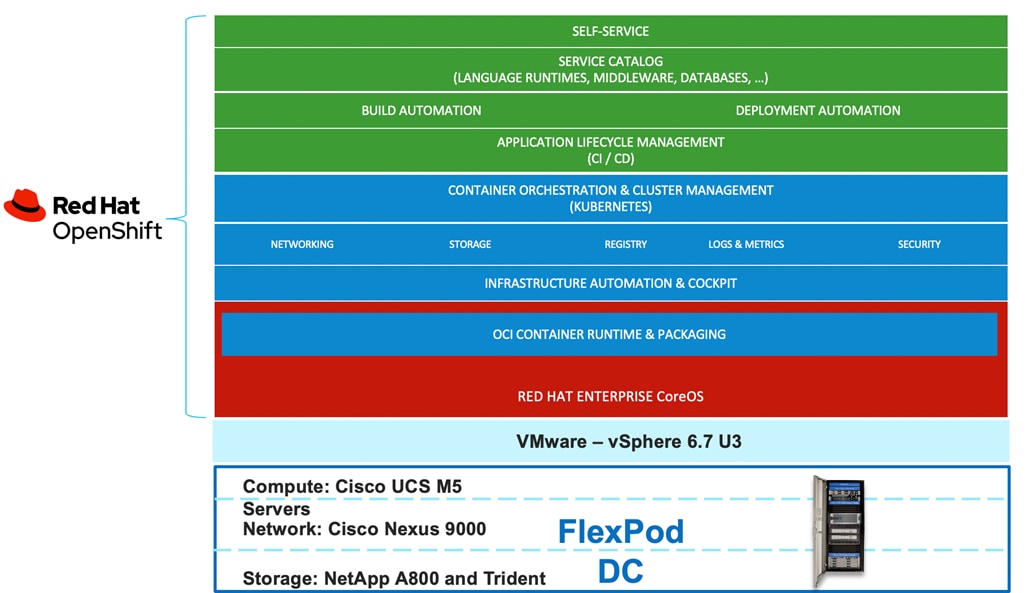
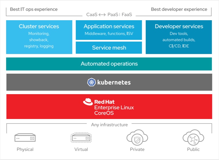
Red Hat® OpenShift® is an enterprise ready Kubernetes container platform to manage hybrid cloud and multi-cloud deployments. Red Hat OpenShift Container Platform includes everything needed for hybrid cloud, enterprise container and Kubernetes development and deployments. It includes an enterprise-grade Linux operating system, container runtime, networking, monitoring, container registry, authentication, and authorization solutions.
Combining Red Hat OpenShift with FlexPod Datacenter solution can simplify the deployment and the management of the container infrastructure. Customers can benefit from improved efficiency, better data protection, lower risk, and the flexibility to scale this highly available enterprise-grade infrastructure stack to accommodate new business requirements. The pre-validated converged solution approach helps organizations achieve the speed, flexibility, and scale required for all of their application modernization and digital transformation initiatives.
Introduction
It is well understood that assembling and integrating off-the-shelf hardware and software components increases solution complexity and lengthens deployment times. As a result, valuable IT resources are wasted on systems integration work that can result in fragmented resources which are difficult to manage and require in-depth expertise to optimize and control various deployments.
To help customers, business partners, and other deployment teams with their digital transformation and to enhance their cloud-native and application modernization practices, this document provides a reference architecture that includes design guidance, best practices, and other recommendations for deploying Red Hat OpenShift Container Platform (OCP) 4 on FlexPod DC architecture. OCP component VMs are deployed on a VMware cluster running on the Cisco UCS Platform. Integration between OCP and the storage and data management services occur at several levels and the design details for the integration are captured in this document.
Audience
The intended audience of this document includes but is not limited to IT architects, sales engineers, field consultants, professional services, IT managers, partner engineering, and customers who want to take advantage of an infrastructure built to deliver IT efficiency and enable IT innovation.
What’s New in this Release?
The following design elements distinguish this version of FlexPod from previous models:
· Deploying Red Hat OpenShift Container Platform (OCP) 4.4 on FlexPod Datacenter infrastructure running vSphere 6.7 Update 3.
· Showcase NetApp storage integration with the underlying container orchestration using NetApp Trident to provision and manage persistent volumes for the containerized applications.
Solution Summary
The FlexPod Datacenter solution for Red Hat OpenShift Container Platform 4 comprises of following core components:
· Compute and networking components from Cisco
· Storage systems and plugins from NetApp
· vSphere hypervisor from VMware
· OpenShift Container Platform software from Red Hat
All these components have been integrated so that the customers can deploy the solution quickly and economically while eliminating many of the risks associated with researching, designing, building, and deploying similar solutions from the ground up.
This joint solution offers the following key benefits:
· Highly available and scalable platform with flexible architecture that supports various deployment models
· Cooperative support model and Cisco Solution Support
· Easy to deploy, consume, and manage architecture which saves time and resources required to research, procure, and integrate off the shelf components
· Integration with NetApp Trident for dynamic provisioning of persistent storage services along with advanced data management capabilities
· Support for enhanced CI/CD workflow and practices associated with DevOps and micro-services
Like all other FlexPod solution designs, FlexPod Datacenter for OCP 4 is configurable according to the demand and usage. Customers can purchase exactly the infrastructure they need for their current application requirements and can then scale-up by adding more resources to the FlexPod system or scale-out by adding more FlexPod instances.
FlexPod Datacenter
FlexPod datacenter architecture is built using the following infrastructure components for compute, network, and storage:
· Cisco Unified Computing System (Cisco UCS)
· Cisco Nexus and Cisco MDS* Switches
· NetApp Storage Systems (FAS, AFF)
![]() * This CVD does not cover Fiber Channel storage connectivity therefore Cisco MDS is not part of the design.
* This CVD does not cover Fiber Channel storage connectivity therefore Cisco MDS is not part of the design.
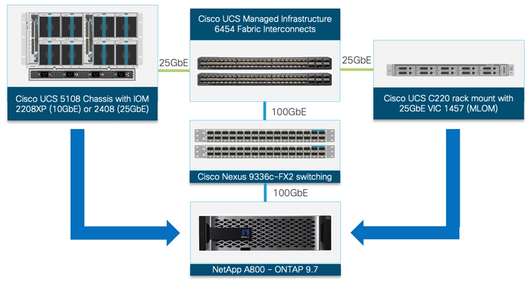
These components are connected and configured according to the best practices of both Cisco and NetApp and provide an ideal platform for running a variety of workloads with confidence. One of the key benefits of FlexPod is the ability to maintain consistency at both scale-up and scale-out models. The current solution comprises of following core components:
· Cisco UCS Manager on Cisco 4th generation 6454 Fabric Interconnects to support 10GbE, 25GbE and 100GbE connectivity from various components.
· Cisco UCS 5108 Chassis with Cisco UCS B200 M5 blade servers and Cisco UCS C220 M5 rack servers to support VMware vSphere environment where Red Hat OCP 4 in deployed.
· High-Speed Cisco NxOS based Nexus 9336C-FX2 switching design to support up to 100GbE connectivity.
· NetApp AFF A800 NVMe storage with 100GbE connectivity to Cisco Nexus switching fabric.
The key features and highlights for these FlexPod components are explained below.
Cisco Unified Computing System
Cisco Unified Computing System™ (Cisco UCS) is a next-generation datacenter platform that integrates computing, networking, storage access, and virtualization resources into a cohesive system designed to reduce total cost of ownership and increase business agility. The system integrates a low-latency, lossless unified network fabric with enterprise-class, x86-architecture servers. The system is an integrated, scalable, multi-chassis platform with a unified management domain for managing all resources.
The Cisco UCS consists of the following subsystems:
· Compute - The compute piece of the system incorporates servers based on latest Intel’s x86 processors. Servers are available in blade and rack form factor, managed by Cisco UCS Manager.
· Network - The integrated network fabric in the system provides a low-latency, lossless, 10/25/40/100 Gbps Ethernet fabric. Networks for LAN, SAN and management access are consolidated within the fabric. The unified fabric uses the innovative Single Connect technology to lowers costs by reducing the number of network adapters, switches, and cables. This lowers the power and cooling needs of the system.
· Virtualization - The system unleashes the full potential of virtualization by enhancing the scalability, performance, and operational control of virtual environments. Cisco security, policy enforcement, and diagnostic features are now extended into virtual environments to support evolving business needs.
· Storage access – Cisco UCS system provides consolidated access to both SAN storage and Network Attached Storage over the unified fabric. This provides customers with storage choices and investment protection. Also, the server administrators can pre-assign storage-access policies to storage resources, for simplified storage connectivity and management leading to increased productivity.
· Management: The system uniquely integrates compute, network and storage access subsystems, enabling it to be managed as a single entity through Cisco UCS Manager software. Cisco UCS Manager increases IT staff productivity by enabling storage, network, and server administrators to collaborate on Service Profiles that define the desired physical configurations and infrastructure policies for applications. Service Profiles increase business agility by enabling IT to automate and provision resources in minutes instead of days.
Cisco UCS Fabric Interconnects
The Cisco UCS Fabric Interconnects (FIs) provide a single point for connectivity and management for the entire Cisco UCS system. Typically deployed as an active-active pair, the system’s FIs integrate all components into a single, highly available management domain controlled by the Cisco UCS Manager. Cisco UCS FIs provide a single unified fabric for the system, with low-latency, lossless, cut-through switching that supports LAN, SAN and management traffic using a single set of cables.
The Cisco UCS 6454 (Figure 3) deployed for this validation, provides the management and communication backbone for the Cisco UCS B-Series Blade Servers, Cisco UCS 5108 B-Series Server Chassis and Cisco UCS Managed C-Series Rack Servers. All servers attached to the Cisco UCS 6454 Fabric Interconnect become part of a single, highly available management domain. In addition, by supporting a unified fabric, the Cisco UCS 6454 provides both the LAN and SAN connectivity for all servers within its domain. The Cisco UCS 6454 supports deterministic, low-latency, line-rate 10/25/40/100 Gigabit Ethernet ports, a switching capacity of 3.82 Tbps, and 320 Gbps bandwidth between FI 6454 and IOM 2208 per 5108 blade chassis, independent of packet size and enabled services.

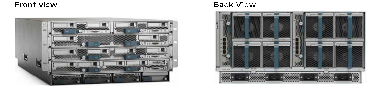
Cisco UCS 5108 Blade Server Chassis
The Cisco UCS 5108 Blade Server Chassis is a fundamental building block of the Cisco Unified Computing System, delivering a scalable and flexible blade server architecture. The Cisco UCS blade server chassis uses an innovative unified fabric with fabric-extender technology to lower TCO by reducing the number of network interface cards (NICs), host bus adapters (HBAs), switches, and cables that need to be managed, cooled, and powered. Cisco UCS 5108 is a 6-RU chassis that can house up to 8 half-width or 4 full-width Cisco UCS B-series blade servers. A passive mid-plane provides up to 80Gbps of I/O bandwidth per server slot and up to 160Gbps for two slots (full-width blades).
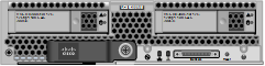
Cisco UCS B200 M5 Servers
The enterprise-class Cisco UCS B200 M5 Blade Server is a half-width blade that delivers performance, flexibility, and optimization within data centers, in the cloud, and at remote sites. The Cisco UCS B200 M5 features:
· 2nd Gen Intel® Xeon® Scalable and Intel Xeon Scalable processors with up to 28 cores per socket
· Up to 3TB of RAM (24 DDR4 DIMMs) for improved performance with up to 12 DIMM slots ready for Intel Optane™ DC Persistent Memory
· Up to 2 Small Form-Factor (SFF) drives
· Up to 2 SD cards or M.2 SATA drives
· Up to 80 Gbps of I/O throughput
For more information about Cisco UCS B-series servers, go to: https://www.cisco.com/c/en/us/products/collateral/servers-unified-computing/ucs-b-series-blade-servers/datasheet-c78-739296.html
Cisco UCS C220 M5
The Cisco UCS C220 M5 Rack Server is a 2-socket, 1-Rack-Unit (1RU) rack server which supports a wide range of storage and I/O-intensive infrastructure workloads. This modular platform offers following capabilities:
· Latest Intel Xeon Scalable CPUs with up to 28 cores per socket
· Up to 3TB of RAM (24 DDR4 DIMMs) for improved performance
· Support for the Intel Optane DC Persistent Memory (128G, 256G, 512G)
· Up to 10 Small-Form-Factor (SFF) 2.5-inch drives or 4 Large-Form-Factor (LFF) 3.5-inch drives
· Support for 12-Gbps SAS modular RAID controller in a dedicated slot, leaving the remaining PCIe Generation 3.0 slots available for other expansion cards
· Modular LAN-On-Motherboard (mLOM) slot that can be used to install a Cisco UCS Virtual Interface Card (VIC) without consuming a PCIe slot
· Dual embedded Intel x550 10GBASE-T LAN-On-Motherboard (LOM) ports
For more information about Cisco UCS C220 M5 servers, go to: https://www.cisco.com/c/en/us/products/collateral/servers-unified-computing/ucs-c-series-rack-servers/datasheet-c78-739281.html
![]()
![]() The solution was validated using both Cisco UCS B200 M5 and C220 M5 servers to show the versatility of the Cisco UCS platform. Customers can choose to deploy OCP on just the Cisco UCS B-Series servers or just the Cisco UCS C-Series servers depending on their requirements.
The solution was validated using both Cisco UCS B200 M5 and C220 M5 servers to show the versatility of the Cisco UCS platform. Customers can choose to deploy OCP on just the Cisco UCS B-Series servers or just the Cisco UCS C-Series servers depending on their requirements.
Cisco UCS VIC 1400
The Cisco UCS Virtual Interface Card (VIC) 1400 Series provides complete programmability of the Cisco UCS I/O infrastructure by presenting virtual NICs (vNICs) as well as virtual HBAs (vHBAs) from the same adapter according to the provisioning specifications within UCSM.
The Cisco UCS VIC 1440 is a dual-port 40-Gbps or dual 4x 10-Gbps Ethernet/FCoE capable modular LAN On Motherboard (mLOM) adapter designed exclusively for the M5 generation of Cisco UCS B-Series Blade Servers. When used in combination with an optional port expander, the Cisco UCS VIC 1440 capabilities are enabled for two ports of 40-Gbps Ethernet. In this CVD, Cisco UCS B200 M5 servers contain the Cisco UCS VIC 1440 adapters.
The Cisco UCS VIC 1457 is a quad-port Small Form-Factor Pluggable (SFP28) mLOM card designed for the M5 generation of Cisco UCS C-Series Rack Servers. The card supports 10/25-Gbps Ethernet or FCoE. The card can present PCIe standards-compliant interfaces to the host, and these can be dynamically configured as either NICs or HBAs. In this CVD, Cisco UCS C220 M5 servers contain the Cisco UCS VIC 1457 adapters.
Cisco UCS Manager
Cisco UCS Manager (UCSM) provides unified, integrated management for all software and hardware components in Cisco UCS. Cisco UCSM manages, controls, and administers multiple blades and chassis enabling administrators to manage the entire Cisco Unified Computing System as a single logical entity through an intuitive GUI, a CLI, as well as a robust API. Cisco UCS Manager is embedded into the Cisco UCS Fabric Interconnects and offers comprehensive set of XML API for third party application integration. Cisco UCSM exposes thousands of integration points to facilitates custom development for automation, orchestration, and to achieve new levels of system visibility and control.
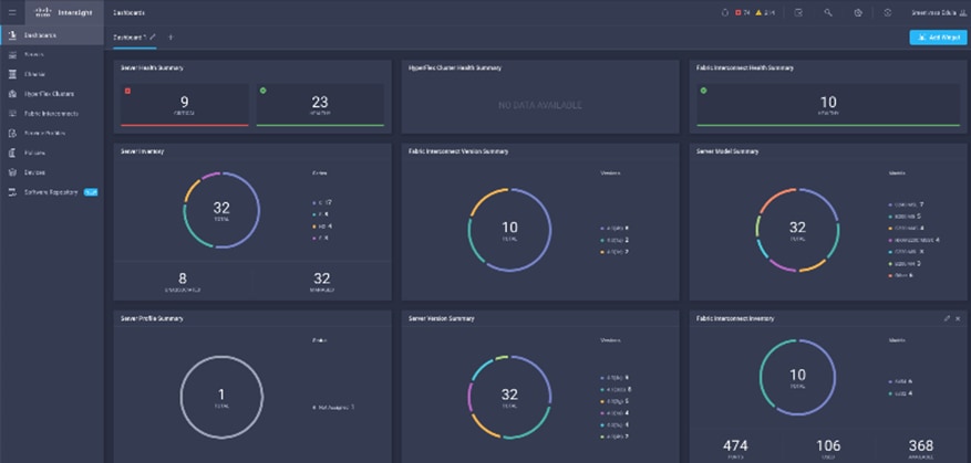
Cisco Intersight
The Cisco Intersight™ platform provides intelligent cloud-powered infrastructure management for Cisco UCS based platforms. Cisco Intersight is a subscription-based, cloud service for infrastructure management that simplifies operations by providing proactive, actionable intelligence for operations. Cisco Intersight provides capabilities such as Cisco Technical Assistance Center (TAC) integration for support and Cisco Hardware Compatibility List (HCL) integration for compliance that Enterprises can leverage for all their Cisco UCS systems in all locations. Cloud-based delivery enables Enterprises to quickly adopt the new features that are continuously being rolled out in Cisco Intersight.
Each Cisco UCS server automatically includes a Cisco Intersight Base edition at no additional cost. In addition, customers can purchase the Cisco Intersight Essentials, Advantage or Premier edition licenses using the Cisco ordering tool. Addition details about licensing and specific features enabled through various licenses are covered here: https://www.cisco.com/c/en/us/products/collateral/servers-unified-computing/intersight/datasheet-c78-739433.html#Licensing.
For more information on Cisco Intersight, go to:
![]() Cisco Intersight is an optional component that can be added to the design.
Cisco Intersight is an optional component that can be added to the design.
Cisco Workload Optimization Manager
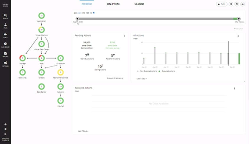
Cisco Workload Optimization Manager (CWOM) is a real-time decision engine that drives continuous health in the IT environment. Its intelligent software constantly analyzes workload consumption, costs, and compliance constraints. It assures application performance by giving workloads the resources they need, when they need them. CWOM provides specific real-time actions that ensure workloads get the resources they need for:
· Placement
· Scaling
· Capacity
Customers can automate the software’s decisions to match their level of comfort:
· Recommend (view only)
· Manual (select and apply)
· Automated (executed in real-time by software
The CWOM dashboard provides views specific to On-Prem, the Cloud, or a Hybrid view of infrastructure, applications, and costs across both.
For more information about the full capabilities of workload optimization, planning, and reporting, see: https://www.cisco.com/c/en/us/products/servers-unified-computing/workload-optimization-manager/index.html
![]() Cisco Workload Optimization Manager is an optional component that can be added to the design.
Cisco Workload Optimization Manager is an optional component that can be added to the design.
Cisco Nexus Switching Fabric
The Cisco Nexus 9000 Series Switches offer both modular and fixed 1/10/25/40/100 Gigabit Ethernet switch configurations with scalability up to 60 Tbps of non-blocking performance with less than five-microsecond latency, wire speed VXLAN gateway, bridging, and routing support.
The Nexus 9000 switch featured in this CVD is the Nexus 9336C-FX2 (Figure 9) configured in NX-OS standalone mode. NX-OS is a purpose-built datacenter operating system designed for performance, resiliency, scalability, manageability, and programmability at its foundation. It provides a robust and comprehensive feature set that meets the demanding requirements of virtualization and automation in present and future datacenters.
The Cisco Nexus 9336C-FX2 Switch is a 1RU switch that supports 36 ports, 7.2 Tbps of bandwidth and over 2.8 bpps. The switch can be configured to work as 1/10/25/40/100-Gbps offering flexible options in a compact form factor. Breakout is supported on all ports.

NetApp AFF Systems
The NetApp all-flash A-Series systems have been designed to provide enterprise-class, scale-out, all-flash storage with the industry’s most advanced data-management capabilities and cloud integration. These systems deliver industry-leading performance, capacity, density, scalability, security, and network connectivity in highly dense form factors.
In the FlexPod Datacenter for RedHat OCP 4 solution, a NetApp AFF A800 system is utilized to provide storage. A few key highlights of the AFF A800 systems include:
· Industry’s first end-to-end NVMe over FC (NVMe/FC) host-to-flash array over 32Gb FC.
· Industry’s first storage system to support 100GbE connectivity.
· Maximum effective capacity of 316.3PB.
· 15TB NVMe solid-state drives (NVMe SSDs) with multistream write (MSW).
· Reduced storage footprint by as much as 37x, 2PB SSD storage in a 2U drive shelf.
Because of all the features and functionality highlighted above, the AFF A800 is the top of the line storage system in terms of performance. There are several other models of all-flash storage systems that are designed to suit different end-user performance requirements and price points. All these systems are managed using the data management capabilities offered by NetApp ONTAP® 9 and can be used to support OpenShift deployments.
ONTAP 9
NetApp storage systems harness the power of ONTAP to simplify the data infrastructure from edge, core, and cloud with a common set of data services and 99.9999 percent availability. NetApp ONTAP 9 data management software from NetApp enables customers to modernize their infrastructure and transition to a cloud-ready datacenter. ONTAP 9 has a host of features to simplify deployment and data management, accelerate and protect critical data, and future-proof infrastructure across hybrid-cloud architectures.
Simplifying Deployment and Data Management
The capability to deploy workloads in a matter of minutes, manage the data, and its mobility in a transparent and secure manner is critical for IT operations. The following are a few key features that enable these capabilities:
· NetApp OnCommand System Manager fast-provisioning workflows. Deploy key workloads with all best practices in a few minutes (from power-on to serving data).
· Best-in-class storage efficiency. Reduce wasted space with data compaction, increase effective capacity with deduplication and store more data in less space with compression.
· ONTAP FabricPool. Tier storage between all flash (performance) and object store (external capacity) as needed and reduce storage cost without compromising on performance, efficiency, or protection. From ONTAP 9.5, FabricPools can also use FlexGroup volumes for the performance tier.
· Quality of Service (QoS). Granular QoS controls that help critical workloads to maintain performance especially in highly shared environments.
Accelerate and Protect Critical Data
The fusion of all-flash storage arrays and ONTAP delivers superior levels of performance and data protection by using these key features:
· NVMe. Achieve extremely high throughput with microsecond latency, thus enabling vastly complex and highly resource-dependent applications to run at ease.
· ONTAP FlexGroup. Scale-out NAS containers with near-infinite capacity and predictable low-latency performance in metadata-heavy workloads with a single namespace.
· NetApp Data Availability Services. Replicate data securely from any ONTAP storage—on-premises or in the cloud. Back up ONTAP data directly to an object container. Easily search and recover lost data with a cloud-native management interface.
· NetApp Volume Encryption. Native volume-level encryption with support for onboard and external key management.
· NetApp MetroCluster™. Maintain business continuity and data availability for business-critical applications.
ONTAP provides excellent versatility by responding quickly to changing business requirements and allowing users to move data freely between on-premises environments and leading cloud providers.
Future-Proof Infrastructure
· Cloud Integration. ONTAP is the most cloud-connected storage management software, with options for software-defined storage (NetApp ONTAP Select) and cloud-native instances in the form of NetApp Cloud Volumes Service (AWS and GCP), Cloud Volumes ONTAP and Azure NetApp Files.
· Seamless scaling and non-disruptive operations. ONTAP supports non-disruptive addition of capacity to existing controllers and scale-out clusters. Upgrade to the latest technologies such as NVMe and 32Gb FC without costly data migrations or outages.
· Integration with emerging applications. ONTAP provides enterprise-grade data services for next-generation platforms and applications such as OpenStack, Hadoop, MongoDB by using the same infrastructure that supports existing enterprise apps.
NVMe
NVMe (non-volatile memory express) is a host controller interface and storage protocol created to accelerate the transfer of data between enterprise and client systems and solid-state drives (SSDs) over a computer's high-speed Peripheral Component Interconnect Express (PCIe) bus. The protocol implementation is based on a subsystem consisting of specific NVMe controllers, namespaces, nonvolatile storage medium, hosts, ports, and an interface between the controller and storage medium. Although replacing SATA-based SSDs with NVMe SSDs might show some performance improvements, full benefit of the increased performance of NVMe is unlocked by implementing an NVMe over Fabric (NVMe-oF) design. The specifications describe an approach to extend NVMe across network fabrics at scale, allowing multiple storage arrays and hosts to exchange data at NVMe speeds. NVMe-oF supports four fabric options: Fiber Channel (FC), InfiniBand, RDMA over Converged Ethernet (RoCE), and Internet Wide Area RDMA Protocol (iWARP).
Transitioning to NVMe-oF using FC is a simpler option today because of the widespread usage of FC as a storage network. By using FC, the SAN is capable of simultaneously supporting both FCP traffic and NVMe/FC traffic. This enables a smooth transition with minimal changes and does not introduce any major technical design changes.
For more information, see the FlexPod End-to-End NVMe White Paper: https://www.cisco.com/c/dam/en/us/products/collateral/servers-unified-computing/ucs-c-series-rack-servers/whitepaper-c11-741907.pdf
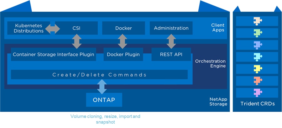
NetApp Trident
Trident is an open-source, fully supported storage orchestrator for containers created by NetApp. With Trident, microservices and containerized applications can take advantage of enterprise-class storage services provided by the full NetApp portfolio of storage systems. In a FlexPod environment, Trident is utilized to allow end users to dynamically provision and manage persistent volumes for containers backed by FlexVols and LUNs hosted on ONTAP-based products such as NetApp AFF and FAS systems.
Trident has a rapid development cycle, and just like Kubernetes, is released four times a year. Starting with the 20.04 release (utilized as part of this solution), the setup of Trident is performed by the Trident operator. The operator makes large scale deployments easier, and provides additional support including self-healing for the pods that are deployed as a part of the Trident install.
VMware vSphere
VMware vSphere is a virtualization platform for holistically managing large collections of infrastructures (resources-CPUs, storage and networking) as a seamless, versatile, and dynamic operating environment. Unlike traditional operating systems that manage an individual machine, VMware vSphere aggregates the infrastructure of an entire data center to create a single powerhouse with resources that can be allocated quickly and dynamically to any application in need.
VMware vSphere vCenter
VMware vCenter Server provides unified management of all hosts and VMs from a single console and aggregates performance monitoring of clusters, hosts, and VMs. VMware vCenter Server gives administrators a deep insight into the status and configuration of compute clusters, hosts, VMs, storage, the guest OS, and other critical components of a virtual infrastructure. VMware vCenter manages the rich set of features available in a VMware vSphere environment.
VMware vSphere Web Client Plugin
The VMware vSphere Web Client is a cross-platform web application used to interact with the VMware vCenter server — for managing clusters, hosts, and virtual machines in datacenters. The Web Client provides full vSphere client functionality including capabilities for configuring hosts, clusters, networks, datastores, or datastore clusters.
RedHat OpenShift Container Platform
RedHat OpenShift Architecture
The RedHat OpenShift Container Platform (OCP) is a container application platform that brings together CRI-0 and Kubernetes and provides an API and web interface to manage these services. CRI-O is an implementation of the Kubernetes CRI (Container Runtime Interface) to enable using Open Container Initiative (OCI) compatible runtimes. It is a lightweight alternative to using Docker as the runtime for Kubernetes.
OCP allows customers to create and manage containers. Containers are standalone processes that run within their own environment, independent of operating system and the underlying infrastructure. OCP helps developing, deploying, and managing container-based applications. It provides a self-service platform to create, modify, and deploy applications on demand, thus enabling faster development and release life cycles. OCP has a microservices-based architecture of smaller, decoupled units that work together. It runs on top of a Kubernetes cluster, with data about the objects stored in etcd, a reliable clustered key-value store.
Kubernetes Infrastructure
Within OpenShift Container Platform, Kubernetes manages containerized applications across a set of CRI-O runtime hosts and provides mechanisms for deployment, maintenance, and application-scaling. The CRI-O service packages, instantiates, and runs containerized applications.
A Kubernetes cluster consists of one or more masters and a set of worker nodes. This solution design includes HA functionality at the hardware as well as the software stack. A Kubernetes cluster is designed to run in HA mode with 3 master nodes and a minimum of 2* worker nodes to help ensure that the cluster has no single point of failure.
![]() * In this deployment, 1 worker node was deployed on each ESXi host for a total of 4 worker nodes.
* In this deployment, 1 worker node was deployed on each ESXi host for a total of 4 worker nodes.
Red Hat Core OS
OpenShift Container Platform uses Red Hat Enterprise Linux CoreOS (RHCOS), a container-oriented operating system that combines some of the best features and functions of the CoreOS and Red Hat Atomic Host operating systems. RHCOS is specifically designed for running containerized applications from OpenShift Container Platform and works with new tools to provide fast installation, Operator-based management, and simplified upgrades. RHCOS includes the following:
· Ignition, which OpenShift Container Platform uses as a firstboot system configuration for initially bringing up and configuring machines.
· CRI-O, a Kubernetes native container runtime implementation that integrates closely with the operating system to deliver an efficient and optimized Kubernetes experience. CRI-O provides facilities for running, stopping, and restarting containers. It fully replaces the Docker Container Engine, which was used in OpenShift Container Platform 3.
· Kubelet, the primary node agent for Kubernetes that is responsible for launching and monitoring containers.
RHCOS was used on all control plane and worker nodes to support automated OCP 4 deployment.
Deployment Server
The deployment server is a Linux VM used to run the OpenShift Container Platform deployment program. This node can also be used to manage the OCP deployment. The deployment node used in this CVD is based on Red Hat Enterprise Linux (RHEL) 7.6*.
![]() *While RHEL 7.6 was utilized during this validation, customers can use a newer RHEL release for their deployments.
*While RHEL 7.6 was utilized during this validation, customers can use a newer RHEL release for their deployments.
Bootstrap Node
The OCP bootstrap node is a temporary server used during cluster provisioning for the initial configuration of the Master nodes to create the permanent cluster control plane. It boots by using an Ignition configuration file that describes how to create the cluster. The bootstrap node is deployed by the automated install process and is manually deleted when the deployment is complete.
Master Node
The OCP master nodes run services that are required to control the Kubernetes cluster. The master machines are the control plane and contain more than just the Kubernetes services for managing the OCP cluster. Multiple master nodes are required in a high availability (HA) environment to allow for failover if the leading master host fails. There are three Master nodes in the validation lab to provide HA cluster and each node is deployed on a separate ESXi host ESXi for additional resiliency.
Worker Node
A worker node provides the runtime environments for containers. Each node in a Kubernetes cluster has the required services to be managed by the master. Nodes also have the required services to run pods, including CRI-O, which is the container engine, Kubelet, which is the service that accepts and fulfills requests for running and stopping container workloads, and a service proxy, which manages communication for pods across workers.
Operators
Operators are both the fundamental unit of the OpenShift Container Platform 4 code base and a convenient way to deploy applications and software components for the applications. In OCP, Operators serve as the platform foundation and remove the need for manual upgrades of operating systems and control plane applications. OpenShift Container Platform Operators such as the Cluster Version Operator and Machine Config Operator allow simplified, cluster-wide management of those critical components.
In the next section, various design parameters and details are discussed in detail.
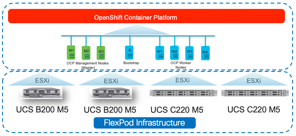
The FlexPod Datacenter for OCP 4 solution utilizes Red Hat Enterprise Linux CoreOS (RHCOS) VMs running on VMware vSphere 6.7 U3 infrastructure. The VMware vSphere ESXi hypervisor is installed on Cisco UCS B200 M5 and C220* M5 servers as shown in Figure 11.
![]() *The solution was validated using both Cisco UCS B200 M5 and C220 M5 servers to show the versatility of the Cisco UCS platform. Customers can choose to deploy OCP on just the Cisco UCS B-Series servers or just the Cisco UCS C-Series servers depending on their requirements.
*The solution was validated using both Cisco UCS B200 M5 and C220 M5 servers to show the versatility of the Cisco UCS platform. Customers can choose to deploy OCP on just the Cisco UCS B-Series servers or just the Cisco UCS C-Series servers depending on their requirements.
The key design requirement and various prerequisites for delivering this new datacenter solution are explained in this section.
Design Requirements
The FlexPod Datacenter solution for OCP 4 closely aligns with NxOS based FlexPod CVDs and meets the following general design requirements:
1. Resilient design across all layers of the infrastructure with no single point of failure.
2. Scalable design with the flexibility to add compute capacity, storage, or network bandwidth as needed.
3. Modular design that can be replicated to expand and grow as the needs of the business grow.
4. Flexible design that can support components beyond what is validated and documented in this guide.
5. Simplified design with ability to automate and integrate with external automation and orchestration tools.
For Red Hat OCP 4 integration into a traditional FlexPod Datacenter solution, the following specific design considerations are also observed:
1. High Availability of master nodes with a minimum of 3 master nodes deployed.
2. A minimum of 4 worker nodes with ability to increase the nodes as the load requirements increase.
3. Automating the OCP installation by utilizing Terraform scripts provided by Red Hat to simplify the installation and reduce the deployment time.
4. Present persistent storage (volumes) to the containerized applications by utilizing the NetApp Trident framework.
Prerequisites
There are various infrastructure services prerequisites for deploying OCP 4. These prerequisites are:
· DNS, DHCP, and NTP services – these services were configured on a RHEL VMs
· Specific DNS entries for deploying OCP – added to the DNS server
· Load Balancer for use by OpenShift – HA Proxy running on a RHEL VM
· An HTTP server to host Ignition configuration files – Apache server on a RHEL VM
· A Linux VM for initial installation and cluster management – a RHEL VM with appropriate packages
Customers can choose to combine some of these services on a single VM e.g. DNS and DHCP on a single VM and can choose to deploy these services on a platform and version of their choice, for example a windows-based DNS or DHCP server. However, during the lab deployment, a dedicated VM was used for each service for clarity and for future scalability.
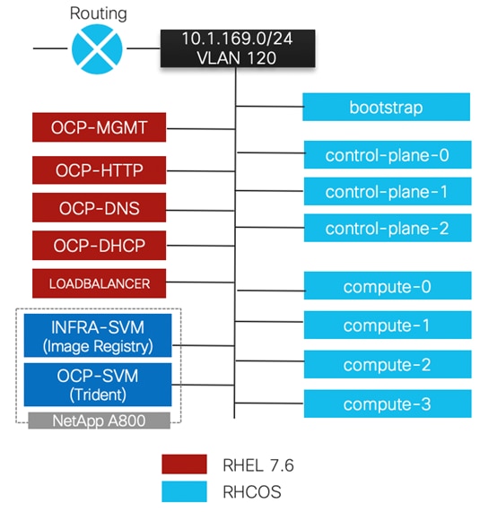
Physical Topology
The physical topology for FlexPod Datacenter for OCP 4 deployment is shown in Figure 12:
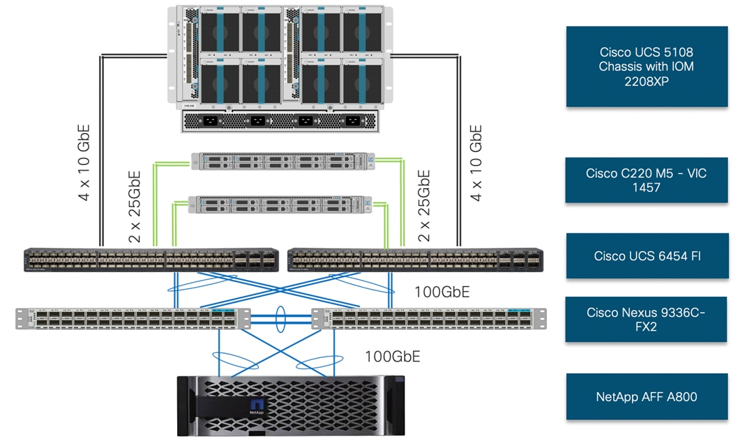
To validate the design, an environment with the following components was setup:
· Cisco UCS 6454 Fabric Interconnects (FI) to support Cisco UCS 5108 chassis and Cisco UCS C220 M5 servers.
· Cisco UCS 5108 chassis connected to FIs using 2208XP IOMs.
· Cisco Nexus 9336C running in NxOS mode provides the switching fabric.
· Cisco UCS 6454 FI’s 100GbE uplink ports were connected to Nexus 9336C as port-channels.
· NetApp AFF A800 controllers connected to Nexus 9336C switch using 100GbE port-channels.
· VMware 6.7 Update 3 ESXi software installed on Cisco UCS B200 M5 and C220 M5 servers.
The following sections explain the connectivity options in greater detail.
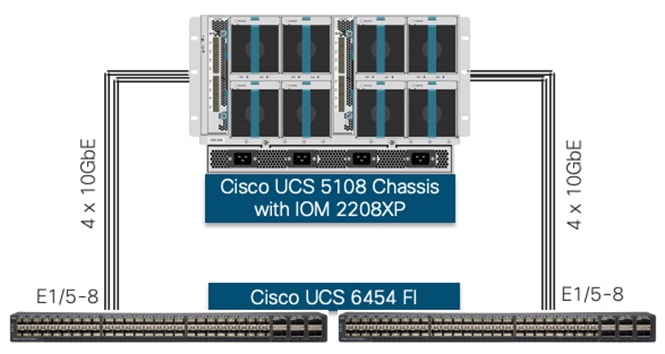
Cisco UCS 5108 Connectivity
The Cisco UCS B-Series servers have been utilized for setting up the VMware environment. Cisco UCS 5108 chassis is equipped with the Cisco UCS 2208XP IO Modules and populated with Cisco UCS B200 M5 blade servers containing Cisco VIC 1440. The servers are configured with appropriate vNICs and diskless iSCSI-based SAN boot to enable stateless compute environment. Figure 13 shows the Cisco UCS 5108 chassis connected to each Cisco UCS 6454 FI using 4 10GbE ports. If the customers require more bandwidth, all 8 ports on Cisco UCS 2208XP IOM can be connected to FI. Customers can also use Cisco UCS IOM 2408 for increased bandwidth since IOM 2408 supports 8 x 25GbE ports.
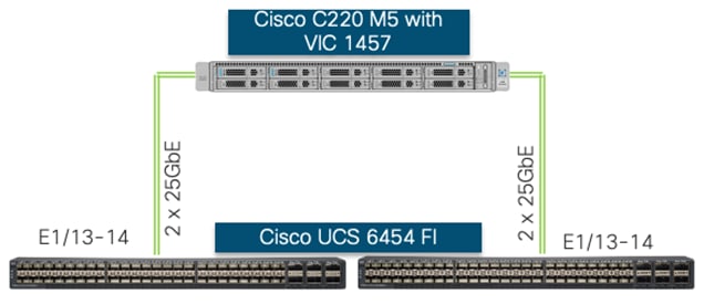
Cisco UCS C220 M5 Connectivity
The Cisco UCS C220 M5, is equipped with Cisco UCS VIC 1457. Cisco UCS VIC 1457 has four 25GbE ports which are connected to the Cisco UCS 6454 FI in pairs such that ports 1 and 2 are connected to the Cisco UCS 6454 FI-A and the ports 3 and 4 are connected to the FI-B as shown in Figure 14. The ports connected to a fabric interconnect form a port-channel providing an effective 50GbE bandwidth to each fabric interconnect.
Service Profile Configuration
The service profile allows compute admins to deploy uniform policies and configurations to both Cisco UCS B200 M5 and C220 M5 servers. Various VLANs utilized in the service profile creation are listed in Table 1.
VLANs Configuration
Table 1 list VLANs configured for setting up the FlexPod environment along with their usage:
| VLAN ID |
Name |
Usage |
| 2 |
Native-VLAN |
Use VLAN 2 as Native VLAN instead of default VLAN (1) |
| 20 |
OOB-MGMT-VLAN |
Out of Band Management VLAN to connect the management ports for various devices |
| 120 |
IB-MGMT-VLAN |
In Band Management VLAN utilized for all the OCP components. This VLAN is also used for accessing NetApp SVMs for NFS volumes |
| 3100 |
vMotion |
VMware vMotion traffic |
| 3111 (Fabric A only) |
iSCSI-A |
iSCSI-A path for supporting boot-from-san for both Cisco UCS B-Series and Cisco UCS C-Series servers |
| 3121 (Fabric B only) |
iSCSI-B |
iSCSI-B path for supporting boot-from-san for both Cisco UCS B-Series and Cisco UCS C-Series servers |
| 3151 |
NFS-VLAN |
NFS VLAN for mounting ESXi datastores to host VMs |
Some of the key highlights of VLAN usage are as follows:
· VLAN 20 allows customers to manage and access out of band management interfaces of various devices.
· VLAN 120 is used for all the OCP infrastructure (DNS, DHCP, and so on) as well as OCP cluster VMs. This VLAN is also utilized for providing access to the dedicated NetApp Storage Virtual Machine (OCP-SVM) used by NetApp Trident for configuring persistent volumes.
· VLAN 3151 provides ESXi hosts access to the NSF datastores hosted on the NetApp Controllers for deploying VMs.
· A pair of iSCSI VLANs (3111 and 3121) are configured to provide access to boot LUNs for ESXi hosts. These VLANs are defined on individual Fabric Interconnects.
Service Profile for VMware Hosts
In FlexPod Datacenter deployments, each Cisco UCS server (B-Series or C-Series), equipped with a Cisco Virtual Interface Card (VIC), is configured for multiple virtual interfaces (vNICs) which appear as standards-compliant PCIe endpoints to the OS. The service profile configuration for an ESXi host is shown in Figure 15.
Each ESXi service profile supports:
· Managing the ESXi hosts using a common management segment
· Diskless SAN boot using iSCSI with persistent operating system installation for true stateless computing
· Six vNICs where
- 2 redundant vNICs (vSwitch0-A and vSwitch0-B) carry out-of-band management, in-band management, and ESXi host NFS datastore VLANs. The MTU value for this interface is set as a Jumbo MTU (9000).
- 2 redundant vNICs (VDS-A and VDS-B) are used by the vSphere Distributed switch and carry VMware vMotion traffic and customer application data traffic. The MTU for these interfaces is set to Jumbo MTU (9000).
- 1 iSCSI-A vNIC utilizes iSCSI-A VLAN (defined only on Fabric A) to provide access to iSCSI-A path. The MTU value for this interface is set as a Jumbo MTU (9000).
- 1 iSCSI-B vNIC utilizes iSCSI-B VLAN (defined only on Fabric B) to provide access to iSCSI-B path. The MTU value for this interface is set as a Jumbo MTU (9000).
· Each ESXi host (blade) accesses NFS datastores hosted on NetApp A800 controllers to be used for deploying virtual machines.
· Each ESXi host provides access to OCP image registry NFS volume using in-band management network.
· Each ESXi host also provides access to a dedicated NetApp SVM utilized by NetApp Trident using in-band management VLAN. Details of this SVM are explained later in the document.
Network Connectivity
Cisco Nexus Features
The Cisco Nexus 9336C-FX2 device configuration covers the core networking requirements for Layer 2 and Layer 3 communication. Some of the key NX-OS features implemented within the design are:
· Feature interface-vlan – Allows for VLAN IP interfaces to be configured within the switch as gateways.
· Feature HSRP – Allows for Hot Standby Routing Protocol configuration for high availability.
· Feature LACP – Allows for the utilization of Link Aggregation Control Protocol (802.3ad) by the port channels configured on the switch.
· Feature VPC – Virtual Port-Channel (vPC) presents the two Nexus switches as a single “logical” port channel to the connecting upstream or downstream device.
· Feature LLDP - Link Layer Discovery Protocol (LLDP), a vendor-neutral device discovery protocol, allows the discovery of both Cisco and non-Cisco devices.
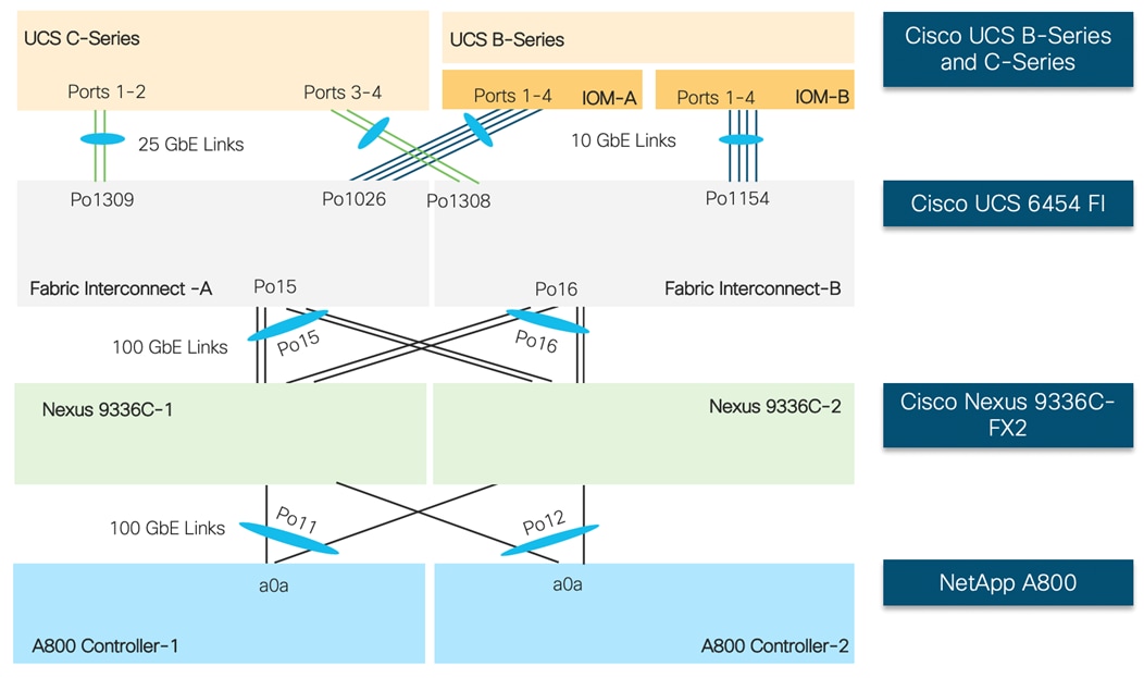
Cisco UCS NetApp A800 Logical Connectivity to Cisco Nexus Switches
Figure 16 shows the connectivity between Cisco UCS servers, Cisco UCS Fabric Interconnects (FI) and NetApp controllers. Each 2208 XP IOM in the Cisco UCS chassis is connected to each Fabric Interconnect using 4 10GbE ports. Each Cisco UCS C-Series server is connected to both the FIs using all 4 25 GbE interfaces (2 ports to each FI). The Cisco UCS FIs and NetApp A800 controllers connect to the Nexus switches using 100GbE interfaces and Port Channels and vPCs (as shown in the figure) are set up for effectively forwarding high speed data. If required, additional links from NetApp A800 and Cisco UCS Fabric Interconnect to Cisco Nexus switches can be deployed for increased bandwidth.
Storage Design
Physical Connectivity
NetApp A800 controllers are connected to Cisco Nexus 9336C-FX2 switches using 100GbE connections. Figure 17 illustrates the physical connectivity design of the NetApp AFF A800 system running ONTAP 9.7.
![]() In Figure 17, the two storage controllers in the high availability pair are drawn separately for clarity. Physically, the two controllers exist within a single chassis.
In Figure 17, the two storage controllers in the high availability pair are drawn separately for clarity. Physically, the two controllers exist within a single chassis.
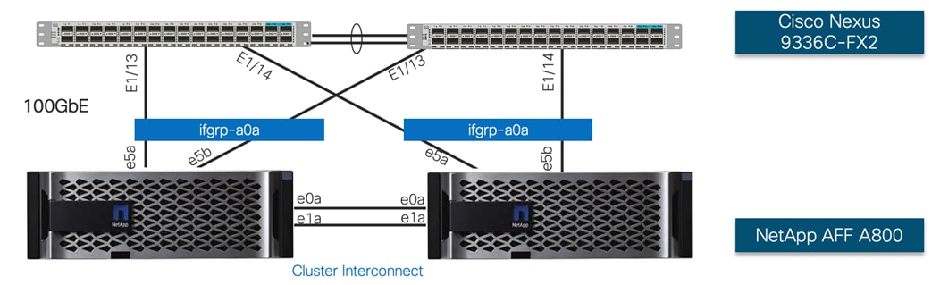
The storage controllers are deployed in a switchless cluster configuration using the onboard ports e0a and e1a. The AFF A800 systems do not have a backplane high availability interconnect and therefore the onboard ports e0b and e1b on both controller nodes were externally connected as the high availability interconnect.
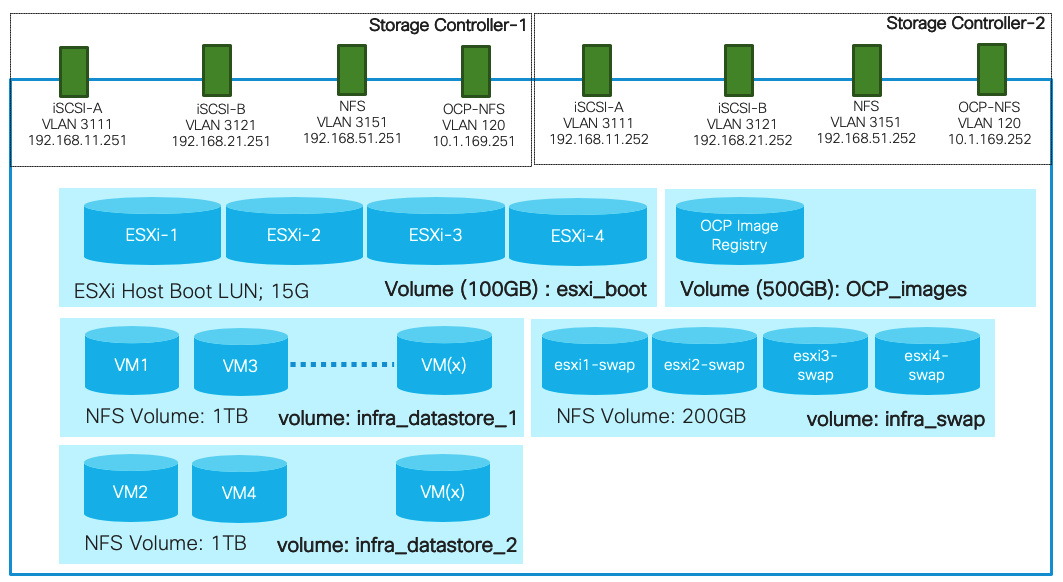
Storage Virtual Machine (SVM) Configuration
To provide the necessary data segregation and management, two separate SVMs are configured for this design. These SVMs are as follows:
· Infra-SVM
- This SVM hosts:
§ ESXi boot LUNs
§ NFS datastores for vSphere environment
§ NFS volume for OCP image registry
The volumes, VLANs, and Interface (LIFs) details are shown in Figure 18.
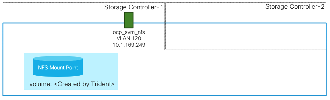
· OCP-SVM
This SVM is used by NetApp Trident to deploy persistent volumes for the container applications.
The persistent volumes are dynamically created by NetApp Trident as needed for the containers. The VLAN and Interface (LIF) details are shown in Figure 19. A single LIF is created in this instance to access the persistent storage volumes. Failover is enabled for this LIF to protect against the controller failures.
Network Connection to Cisco Nexus 9336C-FX2
Each controller node includes two 100GbE ports that are bundled together as an interface group (ifgrp) ‘a0a’ with multimode_lacp. All ports are active at any given point and with ‘multimode_lacp’ they can instantly detect link failures and rebalance the traffic on the surviving links, enabling a highly available system with excellent performance.
Multiple VLAN interfaces are created on the ifgrp for management, NFS and iSCSI data traffic.
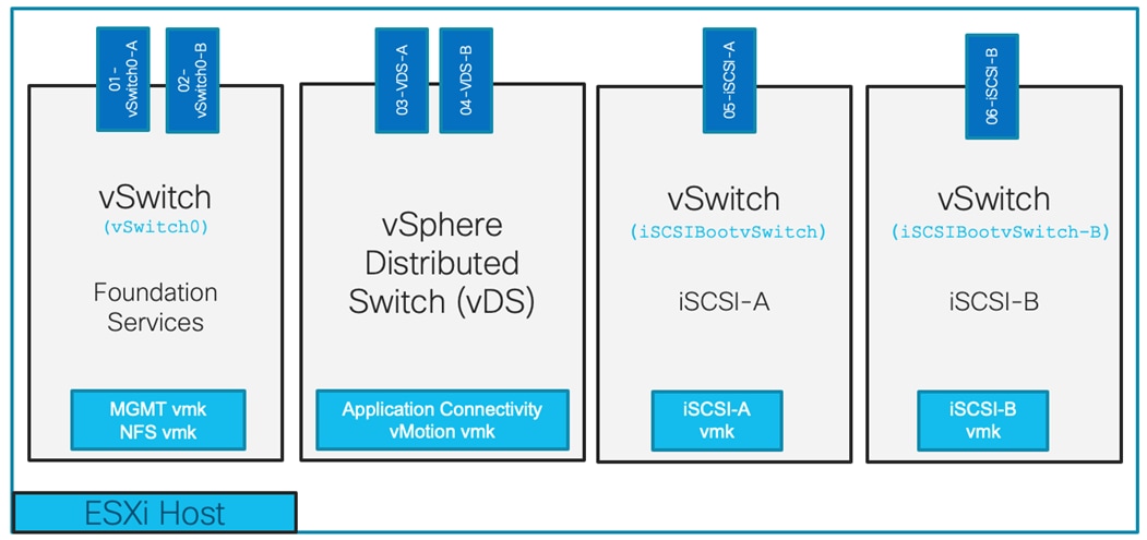
VMware vSphere - ESXi Design
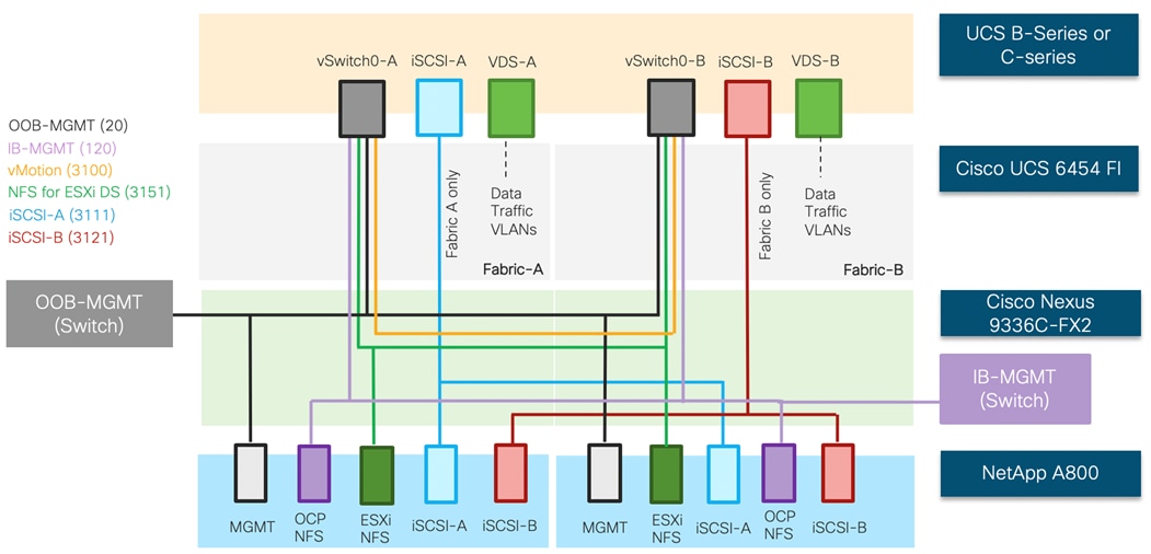
Cisco UCS Service Profiles allow flexible network interface configurations based on customer requirements and multiple vNICs are created for the ESXi hosts in this design. The vNIC distribution for the ESXi hosts is as follows:
· Two vNICs (one on each Fabric) for vSwitch0 to support core services such as management access and NFS datastore access.
· Two vNICs (one on each Fabric) for vSphere Virtual Distributed Switch (VDS) to support customer data traffic and vMotion traffic.
· One vNIC each for Fabric-A and Fabric-B for iSCSI stateless boot. These vNICs use the appropriate fabric’s iSCSI VLAN as the native VLAN and are attached to the iSCSI boot vSwitches.
Figure 20 shows the ESXi vNIC configuration in detail.
OpenShift Container Platform Design
OCP 4.4 is deployed on the VMware infrastructure as a set of VMs. Each VM is a node with a role to carry specific functions within the OCP-Kubernetes cluster. The control plane, which is composed of master machines, manages the OCP cluster. The control plane machines manage workloads on the compute machines known as worker machines.
Three master nodes and four worker nodes are deployed in the validation environment and additional worker nodes can easily be added to increase the scalability of the solution. Figure 21 shows various VMs used for deploying and managing a Red Hat OCP cluster:
The specific role and sizing guidelines for these VMs are explained in the following section.
OCP Virtual Machine Deployment
The FlexPod Datacenter for OCP was built on a 4-node ESXi Cluster using two Cisco UCS B200 M5 and two Cisco UCS C220 M5 servers. The following infrastructure service VMs were deployed to support the OCP cluster:
· 1 DNS server (RHEL 7.6)
· 1 HA Proxy Load Balancer (RHEL 7.6)
· 1 Web/HTTP Server (RHEL 7.6)
· 1 DHCP Server (RHEL 7.6)
The deployment details for these VMs are listed in Table 2.
| Machine |
OS |
vCPU |
RAM (GB) |
Storage (GB) |
Comment |
| DNS |
RHEL 7.6* |
2 |
8 |
100 |
DNS servers for the lab validation |
| DHCP |
RHEL 7.6* |
2 |
4 |
100 |
DHCP server for the lab validation |
| HTTP |
RHEL 7.6* |
2 |
4 |
100 |
Apache Server on RHEL |
| MGMT |
RHEL 7.6* |
2 |
8 |
100 |
This node is used to deploy and manage OCP. Various packages including terraform are installed |
| HA Proxy |
RHEL 7.6* |
2 |
16 |
100 |
Single Load Balancer instance for the lab validation |
![]() The VM sizes listed above are for lab deployment only. Customers should size their VMs according to their individual requirements.
The VM sizes listed above are for lab deployment only. Customers should size their VMs according to their individual requirements.
![]() * While RHEL 7.6 was utilized during this validation, customers can use newer RHEL releases for their specific deployments. Most of these services should already be deployed in the customer environments.
* While RHEL 7.6 was utilized during this validation, customers can use newer RHEL releases for their specific deployments. Most of these services should already be deployed in the customer environments.
OpenShift Container Platform - Virtual Machines
The following OCP Virtual Machines were set up by the terraform scripts for the cluster deployment:
· 1 Bootstrap VM (Red Hat CoreOS - RHCOS)
· 3 Control Plane VMs (RHCOS)
· 4 Compute Node VMs (RHCOS)
The bootstrap VM can be safely deleted when the OCP cluster is installed. These VMs are deployed using VMware OVA therefore the resources required are automatically set by the OVA and the OCP installer. Table 3 lists the number of VMs and their specifications as deployed in this validation.
| Machine |
Number of Nodes |
OS |
vCPU |
RAM (GB) |
Storage (GB) |
Comment |
| Bootstrap |
1 |
RHCOS |
4 |
16 |
60 |
Bootstrap node |
| Control plane |
3 |
RHCOS |
4 |
16 |
60 |
Control plane/Master nodes |
| Compute |
4* |
RHCOS |
4 |
8 |
60 |
Compute/Worker nodes |
OpenShift Container Networking Configuration
OpenShift Container Platform Management Connectivity
Master nodes and Worker nodes have management connectivity using the in-band management VLAN (120) as shown in Figure 21. This VLAN is defined on vSwitch0 of all the ESXi hosts and customer routing and switching network provides network access to the Internet for downloading various packages during OCP installation. In the lab validation, the in-band management network was utilized to deploy all the VMs and associated services including access to storage. Customers can also choose to deploy the OCP VMs using an application data VLAN on the ESXi VDS.
OpenShift Container Platform Storage Connectivity
OpenShift Container Platform VMs requires access to NetApp for the following two types of storage configurations:
1. An NFS volume to host Image Registry in the Infra-SVM. OpenShift provides an integrated Docker registry that adds the ability to provision new image repositories on the fly. This allows users to automatically have a place for their builds to push the resulting images. This image registry utilizes the NFS volume in the Infra-SVM as its storage.
2. Management and data (NFS) access to a dedicated SVM (OCP-SVM) for NetApp Trident. NetApp Trident accesses the NetApp A800 controller and provisions the persistent volumes in the OCP-SVM as needed for various applications.
As shown in Figure 21, this connectivity is achieved by defining data and management LIFs in the in-band management subnet over VLAN 120. All the VMs and Trident then have direct access to NFS mount points and NetApp Trident can access the A800 Management interface for persistent volume configurations.
OpenShift Container Platform Installation
The OpenShift Container Platform installation program can be used to deploy an OCP cluster on infrastructure that the installation program provisions and the cluster maintains (e.g. cloud infrastructure) or deploy a cluster on infrastructure that customer admins prepare and maintain (e.g. FlexPod Datacenter). These two basic types of OpenShift Container Platform clusters are frequently called installer-provisioned infrastructure (IPI) clusters and user-provisioned infrastructure (UPI) clusters. The FlexPod Datacenter for OCP utilizes UPI cluster configuration therefore when provisioning and managing the FlexPod DC infrastructure for the OCP cluster, you must provide all of the cluster infrastructure and resources, including the bootstrap machine, networking, load balancing, storage, and individual cluster machines. You use the installation program to generate the assets that you require to provision the cluster infrastructure, create the cluster infrastructure, and then deploy the cluster to the infrastructure that you provided.
For the UPI install. following cluster resources are required:
· The control plane and compute machines that make up the cluster
· Load balancers
· Cluster networking, including the DNS records and required subnets
· Storage for the cluster infrastructure and applications
![]() For the user-provisioned infrastructure, RHEL based worker VMs can also be deployed however for this validation, RHCOS was used for both the control and worker VMs.
For the user-provisioned infrastructure, RHEL based worker VMs can also be deployed however for this validation, RHCOS was used for both the control and worker VMs.
Installation Process Details
Because each machine in the cluster requires information about the cluster when it is provisioned, OCP uses a temporary bootstrap VM during initial configuration to provide the required information to the permanent control plane. This VM boots by using an Ignition config file that describes how to create the cluster. The bootstrap machine creates the master machines that make up the control plane. The control plane machines then create the compute machines (also known as worker machines). After the cluster machines initialize, the bootstrap machine can be safely deleted. Figure 22 illustrates this process.
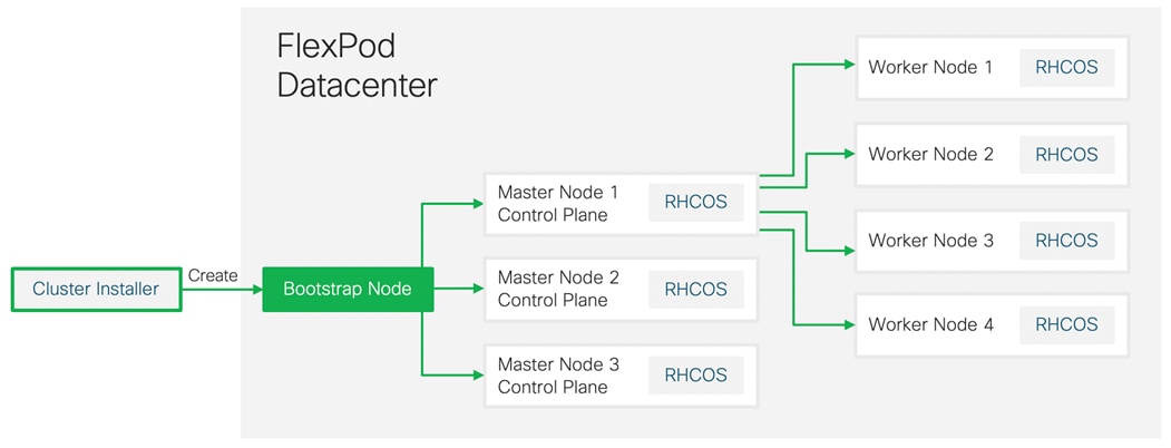
Bootstrapping a cluster involves the following high-level steps:
1. The bootstrap machine boots and starts hosting the remote resources required for the master machines to boot.
2. The master machines fetch the remote resources from the bootstrap machine and finish booting.
3. The master machines use the bootstrap machine to form an etcd cluster.
4. The bootstrap machine starts a temporary Kubernetes control plane using the new etcd cluster.
5. The temporary control plane schedules the production control plane to the master machines.
6. The temporary control plane shuts down and passes control to the production control plane.
7. The bootstrap machine injects OpenShift Container Platform components into the production control plane.
8. The control plane sets up the worker nodes.
9. The control plane installs additional services in the form of a set of Operators.
10. Customers can manually delete the bootstrap machine when the installation completes.
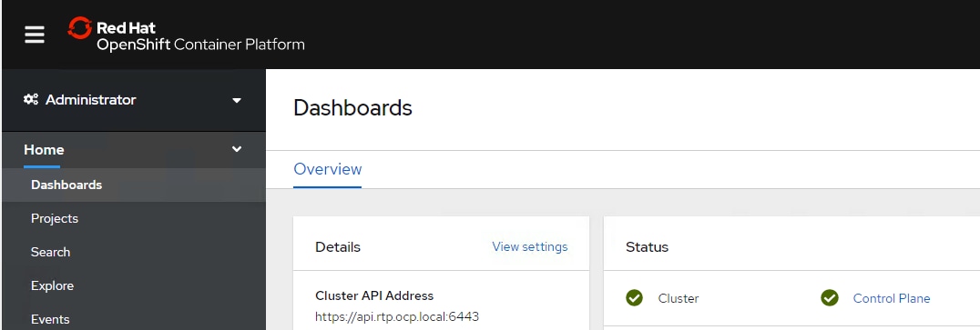
The result of this bootstrapping process is a fully running OCP cluster. The cluster then downloads and configures remaining components needed for the day-to-day operation, including the creation of additional worker machines in supported environments. After successful setup of the OCP environment, users should be able to log into the OCP dashboard using a web browser:
All the control and worker nodes will be deployed on the VMware infrastructure and visible under the dashboard (Figure 24).
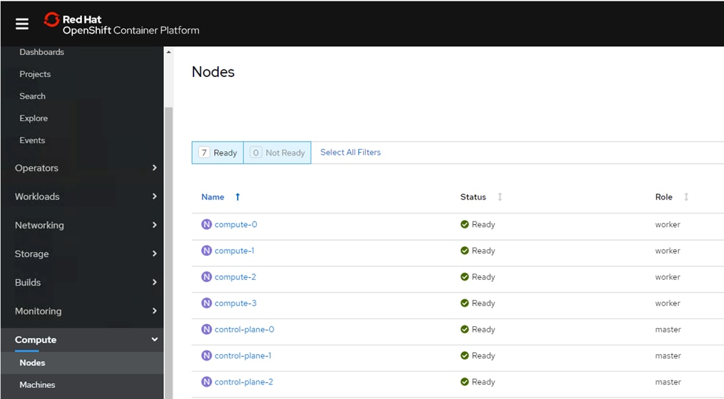
The cluster can now be configured to use the NFS volume on NetApp as the image registry. NetApp Trident can also be deployed to configure persistent container volumes for the containers.
Container Storage Configuration
NetApp Trident allows end users to take advantage of the underlying capabilities of the NetApp storage infrastructure without having to concern themselves with backend management.
To prepare a FlexPod environment to install Trident, it is recommended that a dedicated SVM be created on the ONTAP system with appropriate LIF(s) and services to support the storage protocols being used. The storage administrator will need to create a backend that supports the specified storage protocol, allows Trident to login to the cluster management LIF, and provide the necessary information regarding SVM and Data LIF, as well as any additional features or limits required for a specific backend being deployed.
To deploy Trident, and to create a backend, the following is required for the system administrator:
· A Linux host with the OpenShift application packages installed and configured to manage OCP (management host).
· Administrative access to the NetApp A800 storage system for creation of SVMs and LIFs.
· Full privileges to the OCP Kubernetes cluster to create namespaces and deploy pods.
· Appropriate utilities to support storage services (iSCSI or NFS) on all Worker Nodes.
This validated design utilizes a dedicated SVM to provide NFS services, with a single data LIF.
![]() The installation steps and associated procedures for the OCP cluster and NetApp Trident deployment are detailed in the deployment guide.
The installation steps and associated procedures for the OCP cluster and NetApp Trident deployment are detailed in the deployment guide.
Design Considerations
Network Considerations
Management Connectivity
Out of band management is handled by an independent switch that could be one currently in place in the customer’s environment. Each physical device had its management interface carried through this out-of-band switch, with in-band management carried as a differing VLAN within the solution for ESXi, vCenter and other virtual management components.
Jumbo Frames
An MTU of 9216 was configured at all network levels to allow jumbo frames as needed by the guest OS and application layer.
Compute Considerations
Boot From SAN
When utilizing UCS Server technology with shared storage, it is recommended to configure boot from SAN and store the boot partitions on remote storage. This enables architects and administrators to take full advantage of the stateless nature of UCS Service Profiles for hardware flexibility across the server hardware and overall portability of server identity. Boot from SAN also removes the need to populate local server storage thereby reducing cost and administrative overhead.
Storage Considerations
Image Repository Volume
OpenShift Container Platform provides a built-in container image registry which runs as a standard workload on the cluster. The registry is configured and managed by an infrastructure operator and provides an out of the box solution for users to manage the images that run their workloads. The registry is typically used as a publication target for images built on the cluster as well as a source of images for workloads running on the cluster. The image registry is configured to use an NFS volume in the Infra-SVM for storing the actual image data.
Dedicated SVM for NetApp Trident
When deploying Trident, a dedicated SVM is created for provisioning persistent container volumes. The data LIF in this SVM is made accessible to the OCP nodes through direct layer-2 access. Since the volumes are created on-demand, a dedicated SVM allows the storage volumes to be kept under this dedicated SVM for the ease of management and segregation.
OpenShift Container Platform Considerations
VMware Anti-Affinity Rules for the Control and Worker VMs
Multiple master nodes are required in a high availability environment to allow for failover if the leading master host fails. Each of these nodes is deployed on a separate ESXi host for redundancy and VMware anti affinity rules are set to keep these VMs distributed at all times.
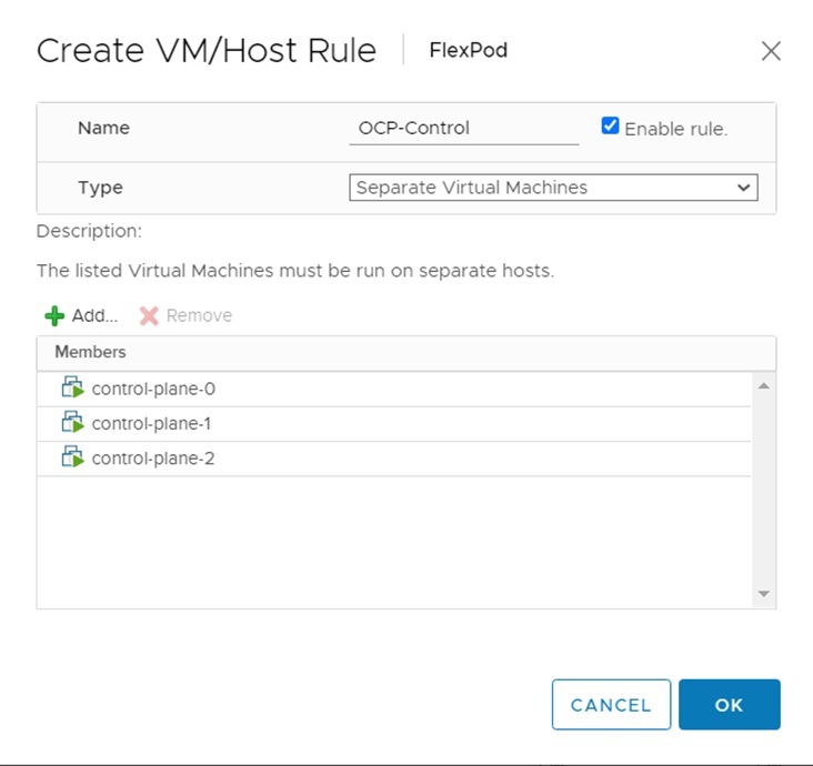
There are multiple (4) worker nodes in the test environment as well. Although not a hard requirement, these VMs are also distributed across the 4 ESXi servers to distribute the load across multiple ESXi servers and for increased resiliency in case of ESXi server failure.
Hardware and Software Revisions
Table 4 Hardware and Software Revisions
| Component |
Software |
|
| Network |
Cisco Nexus 9336C-FX2 |
7.0(3)I7(6) |
| Compute |
Cisco UCS Fabric Interconnect 6454 |
4.0(4g) |
|
|
Cisco UCS B-Series and C-Series M5 Servers |
4.0(4g) |
|
|
VMware ESXi |
6.7 U3 |
|
|
ESXi ENIC Driver |
1.0.29.0 |
|
|
VMware vCenter Appliance |
6.7 U3 |
| Storage |
NetApp A800 |
9.7 |
|
|
NetApp NFS Plugin for VMware VAAI |
1.1.2-3 |
|
|
NetApp Virtual Storage Console |
9.7 |
|
|
NetApp Trident |
20.04 |
| Software |
OpenShift Container Platform |
4.4.12 |
|
|
Red Hat CoreOS |
4.4.3 |
The FlexPod Datacenter for Red Hat OpenShift Container Platform 4 delivers seamless integration of Red Hat’s enterprise grade container platform into the current FlexPod portfolio to enable repeatable, successful customer deployments using:
· FlexPod Portfolio: Pre-validated infrastructure for a wide variety of customer workloads.
· Red Hat’s OpenShift Container Platform: Open-source, enterprise-grade Kubernetes environment that empowers developers and DevOps to each respectively focus on creating robust applications and deploy them at scale.
· NetApp Trident: Fully supported open-source project that integrates natively with Kubernetes and its Persistent Volume framework to seamlessly provision and manage volumes from systems running NetApp’s ONTAP.
Appendix
Compute
Cisco Unified Computing System:
http://www.cisco.com/en/US/products/ps10265/index.html
Cisco UCS 6400 Series Fabric Interconnects:
Cisco UCS 5100 Series Blade Server Chassis:
http://www.cisco.com/en/US/products/ps10279/index.html
Cisco UCS 2400 Series Fabric Extenders:
Cisco UCS 2200 Series Fabric Extenders:
https://www.cisco.com/c/en/us/products/collateral/servers-unified-computing/ucs-6300-series-fabric-interconnects/data_sheet_c78-675243.html
Cisco UCS B-Series Blade Servers:
http://www.cisco.com/en/US/partner/products/ps10280/index.html
Cisco UCS C-Series Rack Servers:
Cisco UCS VIC Adapters:
http://www.cisco.com/en/US/products/ps10277/prod_module_series_home.html
Cisco UCS Manager:
http://www.cisco.com/en/US/products/ps10281/index.html
Network and Management
Cisco Nexus 9000 Series Switches:
http://www.cisco.com/c/en/us/products/switches/nexus-9000-series-switches/index.html
Cisco Nexus 9000 vPC Configuration Guide:
https://www.cisco.com/c/en/us/td/docs/switches/datacenter/nexus9000/sw/6-x/interfaces/configuration/guide/b_Cisco_Nexus_9000_Series_NX-OS_Interfaces_Configuration_Guide/b_Cisco_Nexus_9000_Series_NX-OS_Interfaces_Configuration_Guide_chapter_0111.html
Cisco Data Center Network Manager:
Storage
NetApp ONTAP
https://docs.netapp.com/ontap-9/index.jsp
Trident
https://netapp-trident.readthedocs.io/en/stable-v20.04/introduction.html
Virtualization Layer
VMware vCenter Server:
http://www.vmware.com/products/vcenter-server/overview.html
VMware vSphere:
https://www.vmware.com/products/vsphere
Red Hat OpenShift Container Platform
OCP 4.4 Documentation:
https://docs.openshift.com/container-platform/4.4/welcome/index.html
Compatibility Matrixes
Cisco UCS Hardware Compatibility Matrix:
https://ucshcltool.cloudapps.cisco.com/public/
Cisco Nexus Recommended Releases for Nexus 9K:
VMware and Cisco Unified Computing System:
http://www.vmware.com/resources/compatibility
NetApp Interoperability Matric Tool:
http://mysupport.netapp.com/matrix/
Haseeb Niazi, Technical Marketing Engineer, Cisco Systems, Inc.
Haseeb Niazi has over 20 years of experience at Cisco in the Datacenter, Enterprise and Service Provider Solutions and Technologies. As a member of various solution teams and Advanced Services, Haseeb has helped many enterprise and service provider customers evaluate and deploy a wide range of Cisco solutions. As a technical marking engineer at Cisco UCS Solutions group, Haseeb focuses on network, compute, virtualization, storage and orchestration aspects of various Compute Stacks. Haseeb holds a master's degree in Computer Engineering from the University of Southern California and is a Cisco Certified Internetwork Expert (CCIE 7848).
Alan Cowles, Solutions Architect, NetApp.
Alan Cowles is a Solutions Architect at NetApp focusing on Converged Infrastructure and Hybrid Cloud solutions, specifically in the Open Source Software space. This role includes researching and implementing new open-source or cloud-based solutions, helping to validate them in our labs in RTP, and publishing the results as Technical Reports, Cisco Validated Designs, or NetApp Verified Architectures. In the world away from work, Alan can be often found running or biking on one of the many trail systems in central North Carolina, playing softball, or hanging out at home with his wife and two children.
Acknowledgements
For their support and contribution to the design, validation, and creation of this Cisco Validated Design, the authors would like to thank:
· Sreeni Edula, Technical Marketing Engineer, Cisco Systems, Inc.