Cisco UCS Integrated Infrastructure for Big Data and Analytics with IBM BigInsights for Apache Hadoop
Available Languages

Cisco UCS Integrated Infrastructure for Big Data and Analytics with IBM Big Insights for Apache Hadoop
Building a 64 Node Hadoop Cluster
Last Updated: August 11, 2016
 Cisco Validated Design
The CVD program consists of systems and solutions designed, tested, and documented to facilitate faster, more reliable, and more predictable customer deployments. For more information visit
http://www.cisco.com/go/designzone.
ALL DESIGNS, SPECIFICATIONS, STATEMENTS, INFORMATION, AND RECOMMENDATIONS (COLLECTIVELY, "DESIGNS") IN THIS MANUAL ARE PRESENTED "AS IS," WITH ALL FAULTS. CISCO AND ITS SUPPLIERS DISCLAIM ALL WARRANTIES, INCLUDING, WITHOUT LIMITATION, THE WARRANTY OF MERCHANTABILITY, FITNESS FOR A PARTICULAR PURPOSE AND NONINFRINGEMENT OR ARISING FROM A COURSE OF DEALING, USAGE, OR TRADE PRACTICE. IN NO EVENT SHALL CISCO OR ITS SUPPLIERS BE LIABLE FOR ANY INDIRECT, SPECIAL, CONSEQUENTIAL, OR INCIDENTAL DAMAGES, INCLUDING, WITHOUT LIMITATION, LOST PROFITS OR LOSS OR DAMAGE TO DATA ARISING OUT OF THE USE OR INABILITY TO USE THE DESIGNS, EVEN IF CISCO OR ITS SUPPLIERS HAVE BEEN ADVISED OF THE POSSIBILITY OF SUCH DAMAGES.
THE DESIGNS ARE SUBJECT TO CHANGE WITHOUT NOTICE. USERS ARE SOLELY RESPONSIBLE FOR THEIR APPLICATION OF THE DESIGNS. THE DESIGNS DO NOT CONSTITUTE THE TECHNICAL OR OTHER PROFESSIONAL ADVICE OF CISCO, ITS SUPPLIERS OR PARTNERS. USERS SHOULD CONSULT THEIR OWN TECHNICAL ADVISORS BEFORE IMPLEMENTING THE DESIGNS. RESULTS MAY VARY DEPENDING ON FACTORS NOT TESTED BY CISCO.
CCDE, CCENT, Cisco Eos, Cisco Lumin, Cisco Nexus, Cisco StadiumVision, Cisco TelePresence, Cisco WebEx, the Cisco logo, DCE, and Welcome to the Human Network are trademarks; Changing the Way We Work, Live, Play, and Learn and Cisco Store are service marks; and Access Registrar, Aironet, AsyncOS, Bringing the Meeting To You, Catalyst, CCDA, CCDP, CCIE, CCIP, CCNA, CCNP, CCSP, CCVP, Cisco, the Cisco Certified Internetwork Expert logo, Cisco IOS, Cisco Press, Cisco Systems, Cisco Systems Capital, the Cisco Systems logo, Cisco Unity, Collaboration Without Limitation, EtherFast, EtherSwitch, Event Center, Fast Step, Follow Me Browsing, FormShare, GigaDrive, HomeLink, Internet Quotient, IOS, iPhone, iQuick Study, IronPort, the IronPort logo, LightStream, Linksys, MediaTone, MeetingPlace, MeetingPlace Chime Sound, MGX, Networkers, Networking Academy, Network Registrar, PCNow, PIX, PowerPanels, ProConnect, ScriptShare, SenderBase, SMARTnet, Spectrum Expert, StackWise, The Fastest Way to Increase Your Internet Quotient, TransPath, WebEx, and the WebEx logo are registered trademarks of Cisco Systems, Inc. and/or its affiliates in the United States and certain other countries.
All other trademarks mentioned in this document or website are the property of their respective owners. The use of the word partner does not imply a partnership relationship between Cisco and any other company. (0809R)
© 2016 Cisco Systems, Inc. All rights reserved.
Table of Contents
Cisco UCS Integrated Infrastructure for Big Data and Analytics
Cisco UCS 6200 Series Fabric Interconnects
Cisco UCS C-Series Rack Mount Servers
Cisco UCS Virtual Interface Cards (VICs)
IBM BigInsights for Apache Hadoop: A complete Hadoop Platform
Port Configuration on Fabric Interconnects
Server Configuration and Cabling for C240M4
Software Distributions and Versions
IBM BigInsights with Apache Hadoop
Red Hat Enterprise Linux (RHEL)
Performing Initial Setup of Cisco UCS 6296 Fabric Interconnects
Configure Fabric Interconnect A
Configure Fabric Interconnect B
Logging Into Cisco UCS Manager
Upgrading UCSM Software to Version 3.1(1g)
Adding a Block of IP Addresses for KVM Access
Creating Pools for Service Profile Templates
Creating Policies for Service Profile Templates
Creating Host Firmware Package Policy
Creating the Local Disk Configuration Policy
Creating a Service Profile Template
Configuring the Storage Provisioning for the Template
Configuring Network Settings for the Template
Configuring the vMedia Policy for the Template
Configuring Server Boot Order for the Template
Configuring Server Assignment for the Template
Configuring Operational Policies for the Template
Installing Red Hat Enterprise Linux 7.2
Setting Up Password-less Login
Creating a Red Hat Enterprise Linux (RHEL) 7.2 Local Repo
Creating the Red Hat Repository Database
Set Up all Nodes to Use the RHEL Repository
Upgrading the Cisco Network driver for VIC1227
Disable Transparent Huge Pages
Configuring Data Drives on Name Node and Other Management Nodes
Configuring Data Drives on Data Nodes
Configuring the Filesystem for NameNodes and DataNodes
Pre-Requisites for IOP Installation
Ambari Server Components Set up
Setting Up Resource Manager (Yarn) High Availability
How to Acquire BigInsights Value-add Services
Cisco and IBM join forces to bring the power of Hadoop, Spark, and SQL into a flexible, open, big data and analytics platform. Over time, big data and analytics have advanced to include both batch and real- time data processing. Hadoop has become a strategic data platform embraced by mainstream enterprises as it offers the fastest path for businesses to unlock value in big data while maximizing existing investments.
IBM® BigInsights for Apache Hadoop is a platform for the analysis and visualization of Internet-scale data volumes, powered by Apache Hadoop, an open source distributed computing platform. It is designed to help IT professionals quickly get started with big data analytics using Hadoop. It facilitates the installation, integration, and monitoring of this open source technology. IBM BigInsights helps organizations quickly build and deploy custom analytics and workloads to capture insights from big data that can then be integrated into existing databases, data warehouses, and business intelligence infrastructures.
SQL on Hadoop enables users to process big data on Hadoop systems enabling SQL-style queries, simplifying the data querying, retrieval and analysis process. IBM BigSQL enables analysts to leverage IBM's strength in SQL engines to provide ANSI SQL access to data across any system from Hadoop, via JDBC or ODBC – seamlessly, whether that data exists in Hadoop or a relational database.
Cisco UCS Integrated Infrastructure for Big Data and Analytics integrates compute, network, storage and management into a cohesive programmable infrastructure that can scale as the workloads demand. It provides an industry-leading solution with seamless integration with enterprise applications.
IBM BigInsights, built on IBM Open Platform (IOP), is designed with analytics, operational excellence and security empowerment in mind.
Cisco UCS Integrated Infrastructure for Big Data and Analytics with IBM BigInsights offers a dependable deployment model for enterprise Hadoop while offering a fast and predictable path for businesses to unlock value in big data. This joint solution is optimized to deliver faster insights into the data and greater performance efficiency while reducing the Total Cost of Ownership (TCO) to the end user.
IBM® BigInsights is a powerful, easy-to-use open source platform that offers both real-time and batch processing capabilities over a wide range of scenarios.
Cisco UCS Integrated Infrastructure for Big Data with IBM BigInsights for Apache Hadoop offers these features and benefits:
· Provides advanced analytics built on Hadoop technology to meet big data analysis requirements.
· Designed for high performance and usability through performance-optimized capabilities,
· Visualization, rich developer tools and powerful analytic functions. Delivers management, security and reliability features to support large-scale deployments and help speed up time to value.
· Integrates with IBM and other information solutions to help enhance data manipulation and management tasks.
· Cisco UCS C-Series Rack-Mount Servers based on Intel Xeon processors complete these offerings, to provide a uniquely capable, industry-leading architectural platform for Hadoop-based applications.
The configuration detailed in the document can be extended to clusters of various sizes depending on what the application demands. Up to 80 servers (5 racks) can be supported with no additional switching in a single UCS domain. Scaling beyond 5 racks (80 servers) can be implemented by interconnecting multiple UCS domains using Nexus 9000 Series switches or Application Centric Infrastructure (ACI), scalable to thousands of servers and to hundreds of petabytes storage, and managed from a single pane using UCS Central.
Audience
This document describes the architecture and deployment procedures for IBM BigInsights on a 64 Cisco UCS C240 M4 node cluster based on Cisco UCS Integrated Infrastructure for Big Data and Analytics. The intended audience of this document includes, but is not limited to, sales engineers, field consultants, professional services, IT managers, partner engineering and customers who want to deploy IBM® BigInsights with Apache Hadoop on Cisco UCS Integrated Infrastructure for Big Data and Analytics.
Solution Summary
This CVD describes in detail the process of installing IBM BigInsights with Apache Hadoop and the configuration details of the cluster. It also details application configurations for IBM BigInsights with Apache Hadoop, the libraries it provides, and best practices and guidelines for running IBM BigInsights for big data applications. The current version of Cisco UCS Integrated Infrastructure for Big Data and Analytics offers the following configurations depending on the compute and storage requirements as shown in Table 1 .
Table 1 Cisco UCS Integrated Infrastructure for Big Data and Analytics Configuration Details
| Performance Optimized Option 1 (UCS-SL-CPA4-P1) |
Performance Optimized Option 2 (UCS-SL-CPA4-P2) |
Performance Optimized Option 3 UCS-SL-CPA4-P3 |
Capacity Optimized Option 1 UCS-SL-CPA4-C1 |
Capacity Optimized Option 2 UCS-SL-CPA4-C2 |
| 2 Cisco UCS 6296 UP, 96 ports Fabric Interconnects |
2 Cisco UCS 6296 UP, 96 ports Fabric Interconnects |
2 Cisco UCS 6332 Fabric Interconnects |
2 Cisco UCS 6296 UP, 96 ports Fabric Interconnects |
2 Cisco UCS 6296 UP, 96 ports Fabric Interconnects |
| 16 Cisco UCS C240 M4 Rack Servers (SFF), each with: 2 Intel Xeon processors E5-2680 v4 CPUs (14 cores on each CPU) |
16 Cisco UCS C240 M4 Rack Servers (SFF), each with: 2 Intel Xeon processors E5-2680 v4 CPUs (14 cores on each CPU) |
16 Cisco UCS C240 M4 Rack Servers (SFF), each with: 2 Intel Xeon processors E5-2680 v4 CPUs (14 cores on each CPU) |
16 Cisco UCS C240 M4 Rack Servers (LFF), each with: 2 Intel Xeon processors E5-2620 v4 CPUs (8 c ores each CPU) |
16 Cisco UCS C240 M4 Rack Servers (LFF), each with: 2 Intel Xeon processors E5-2620 v4 CPUs (8c ores each CPU) |
| 256 GB of memory Cisco 12-Gbps SAS Modular Raid Controller with 2-GB flash-based write cache (FBWC) 24 1.2-TB 10K SFF SAS drives (460 TB total) 2 240-GB 6-Gbps 2.5-inch Enterprise Value SATA SSDs for Boot Cisco UCS VIC 1227 (with 2 10 GE SFP+ ports) |
256 GB of memory Cisco 12-Gbps SAS Modular Raid Controller with 2-GB flash-based write cache (FBWC) 24 1.8-TB 10K SFF SAS drives (691 TB total) 2 240-GB 6-Gbps 2.5-inch Enterprise Value SATA SSDs for Boot Cisco UCS VIC 1227 (with 2 10 GE SFP+ ports) |
256 GB of memory Cisco 12-Gbps SAS Modular Raid Controller with 2-GB flash-based write cache (FBWC) 24 1.8-TB 10K SFF SAS drives (691 TB total) 2 240-GB 6-Gbps 2.5-inch Enterprise Value SATA SSDs for Boot Cisco UCS VIC 1387 (with 2 40 GE SFP+ ports) |
128 GB of memory Cisco 12-Gbps SAS Modular Raid Controller with 2-GB flash-based write cache (FBWC) 12 6-TB 7.2K LFF SAS drives (1152 TB total) 2 240-GB 6-Gbps 2.5-inch Enterprise Value SATA SSDs for Boot Cisco UCS VIC 1227 (with 2 10 GE SFP+ ports) |
256 GB of memory Cisco 12-Gbps SAS Modular Raid Controller with 2-GB flash-based write cache (FBWC) 12 8-TB 7.2K LFF SAS drives (1536 TB total) 2 240-GB 6-Gbps 2.5-inch Enterprise Value SATA SSDs for Boot Cisco UCS VIC 1227 (with 2 10 GE SFP+ ports) |
Cisco UCS Integrated Infrastructure for Big Data and Analytics
The Cisco UCS Integrated Infrastructure for Big Data and Analytics solution for IBM BigInsights with Apache Hadoop is based on Cisco UCS Integrated Infrastructure for Big Data and Analytics, a highly scalable architecture designed to meet a variety of scale-out application demands with seamless data integration and management integration capabilities built using the following components:
Cisco UCS 6200 Series Fabric Interconnects
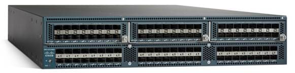
Cisco UCS 6200 Series Fabric Interconnects provide high-bandwidth, low-latency connectivity for servers, with integrated, unified management provided for all connected devices by Cisco UCS Manager (Figure 1). Deployed in redundant pairs, Cisco fabric interconnects offer the full active-active redundancy, performance, and exceptional scalability needed to support the large number of nodes that are typical in clusters serving big data applications. Cisco UCS Manager enables rapid and consistent server configuration using service profiles, automating ongoing system maintenance activities such as firmware updates across the entire cluster as a single operation. Cisco UCS Manager also offers advanced monitoring with options to raise alarms and send notifications about the health of the entire cluster.
Figure 1 Cisco UCS 6296UP 96-Port Fabric Interconnect
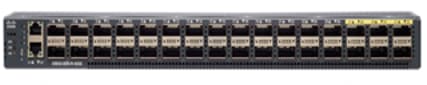
Cisco UCS 6300 Series Fabric Interconnects
Cisco UCS 6300 Series Fabric Interconnects is the new series of Fabric Interconnects that Cisco introduced (Figure 2). The Cisco UCS 6300 series Fabric interconnects are a core part of Cisco UCS, Providing low-latency, lossless 10 and 40 Gigabit Ethernet, Fiber Channel over Ethernet (FCoE), and Fiber Channel functions with management capabilities for system. All servers attached to Fabric interconnects become part of a single, highly available management domain.
Figure 2 Cisco UCS 6332 UP 32 -Port Fabric Interconnect
Cisco UCS C-Series Rack Mount Servers
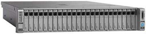
Cisco UCS C-Series Rack Mount C220 M4 High-Density Rack Servers (Small Form Factor Disk Drive Model) (Figure 3), and Cisco UCS C240 M4 High-Density Rack Servers (Small Form Factor Disk Drive Model) (Figure 4), are enterprise-class systems that support a wide range of computing, I/O, and storage-capacity demands in compact designs.
Cisco UCS C-Series Rack-Mount Servers are based on the Intel Xeon E5-2600 v3 and v4 series processors family that delivers the best combination of performance, flexibility and efficiency gains with 12-Gbps SAS throughput. The Cisco UCS C240 M4 servers provides 24 DIMM (PCIe) 3.0 slots and can support up to 1.5 TB of main memory (128 or 256 GB is typical for big data applications). It can support a range of disk drive and SSD options; twenty-four Small Form Factor (SFF) disk drives plus two (optional) internal SATA boot drives for a total of 26 internal drives are supported in the Performance-optimized option or twelve Large Form Factor (LFF) disk drives option plus two (optional) internal SATA boot drives for a total of 14 internal drives are supported in the Capacity-optimized option. Along with 2x1 Gigabit Ethernet embedded LAN-on-motherboard (LOM) ports. Cisco UCS virtual interface cards 1227 (VICs), are designed for the M4 generation of Cisco UCS C-Series Rack Servers, are optimized for high-bandwidth and low-latency cluster connectivity, with support for up to 256 virtual devices that are configured on demand through Cisco UCS Manager.
Figure 3 Cisco UCS C220 M4 Rack Server (Small Form Factor Disk Drive Model)
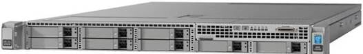
Figure 4 Cisco UCS C240 M4 Rack Server
Cisco UCS Virtual Interface Cards (VICs)
Cisco UCS Virtual Interface Cards (VICs) are unique to Cisco. Cisco UCS Virtual Interface Cards incorporate next-generation converged network adapter (CNA) technology from Cisco, and offer dual 10-Gbps ports designed for use with Cisco UCS C-Series Rack-Mount Servers. Optimized for virtualized networking, these cards deliver high performance and bandwidth utilization, and support up to 256 virtual devices. The Cisco UCS Virtual Interface Card (VIC) 1227 (Figure 5) is a dual-port, Enhanced Small Form-Factor Pluggable (SFP+), 10 Gigabit Ethernet, and Fiber Channel over Ethernet (FCoE)-capable, PCI Express (PCIe) modular LAN on motherboard (mLOM) adapter. It is designed exclusively for the M4 generation of Cisco UCS C-Series Rack Servers and the C3160 dense storage servers.
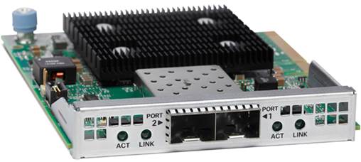
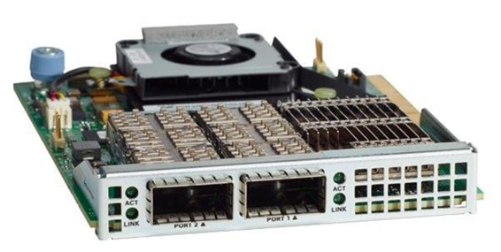
The Cisco UCS Virtual Interface Card 1387 (Figure 6) offers dual-port Enhanced Quad Small Form-Factor Pluggable (QSFP+) 40 Gigabit Ethernet and Fiber Channel over Ethernet (FCoE) in a modular-LAN-on-motherboard (mLOM) form factor. The mLOM slot can be used to install a Cisco VIC without consuming a PCIe slot providing greater I/O expandability.
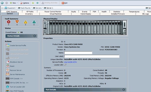
Cisco UCS Manager
Cisco UCS Manager (Figure 7) resides within the Cisco UCS 6200 Series Fabric Interconnect. It makes the system self-aware and self-integrating, managing all of the system components as a single logical entity. Cisco UCS Manager can be accessed through an intuitive graphical user interface (GUI), a command-line interface (CLI), or an XML application-programming interface (API). Cisco UCS Manager uses service profiles to define the personality, configuration, and connectivity of all resources within Cisco UCS, radically simplifying provisioning of resources so that the process takes minutes instead of days. This simplification allows IT departments to shift their focus from constant maintenance to strategic business initiatives.
IBM BigInsights for Apache Hadoop: A complete Hadoop Platform
With IBM BigInsights 4.2 (Figure 8), IBM provides the full range of analytics for Hadoop, Spark and SQL over an open and flexible platform. This platform combines batch processing, SQL, streaming and complex analytics seamlessly for any application to handle a wide range of data processing scenarios.
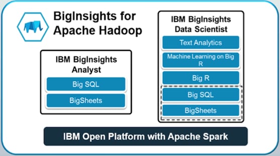
IBM BigInsights built on IBM IOP is designed with analytics, operational excellence and security empowerment in mind.
IBM BigInsights with Apache Hadoop at the core:
· Provides advanced analytics built on Hadoop technology (IBM BigInsights Data Scientist module) to meet big data analysis requirements.
· Designed for performance and usability (IBM BigInsights Analyst module) through performance optimized capabilities, visualization, rich developer tools and powerful analytic functions.
· Delivers management, security and reliability features (IBM Enterprise Management module) to support large-scale deployments and help speed time to value.
· Integrates with IBM and other information solutions to help enhance data manipulation and management tasks.
IBM BigInsights with Apache Hadoop provides a scalable, flexible, integrated platform that makes it easy to manage rapidly increasing volumes and varieties of data in any enterprise. Industry-leading IBM BigInsights with Apache Hadoop products and solutions enable to deploy and manage Apache Hadoop and related projects, manipulate and analyze data, and keep that data secure and protected.
The Lambda Architecture
The Lambda Architecture (Figure 9) describes a 3-layered architecture with responsibilities and characteristics for each layer, which can be implemented by different technologies. The Lambda Architecture offers a widely used framework that addresses the convergence of streaming and batch analytics in a big data world. IBM provides products that are needed to implement the Lambda Architecture. IBM BigInsights IOP can be used for the Lambda Architecture’s batch layer that holds a repository of data and pre-computes the batch views. Apache Spark Streaming can be used for the speed layer that computes the incremental real-time views. The serving layer batch and real-time views can be stored in BigInsights and queried using the BigSQL capabilities of BigInsights. Organizations can implement variations of each layer to suit specific needs. The streaming feed can be used to compute all views once through the stream processing engine and remove the need to constantly re-compute batch views over the entire data set. Streaming jobs can also be used to re-compute historical data from Kafka using its own log of the data or by re-feeding it to Kafka from Apache Hadoop.
Stream computing continuously integrates and analyzes data in motion to deliver analytics, and it consists of both a development environment and high-speed runtime architecture. It also enables organizations to detect insights—risks and opportunities—in data streams that can be detected only at a moment’s notice. High-velocity data flows remain largely unusable from sources like market data, Internet of Things sensors, mobile devices, clickstreams and transactions with out real time processing. Combining all of these together the below Lambda Architecture diagram describes the implementation specifically with IBM products.

IBM IOP
IBM Open Platform (IOP) with Apache Hadoop and Apache Spark is IBM’s big data platform. IOP is built on 100% open source Apache Ecosystem components. It is designed for flexible and efficient analytics and operations.
Key features of IBM Open Platform with Apache Hadoop include:
· Ambari operational framework for provisioning, managing & monitoring Apache Hadoop clusters.
· Native support for rolling upgrades for Hadoop services.
· Support for long-running applications within YARN:
- Higher cluster utilization.
- Lower operational costs.
- Reduced data motion.
Integration with Apache Spark
IBM IOP includes integration with Apache Spark 1.6.1. The benefits include fast processing from the Spark core, near real-time analytics with Spark streaming, built-in machine learning libraries that are highly extensible using Spark MLlib, querying of unstructured data and more value from free-form text analytics with Spark SQL, and graph computation/graph analytics with Spark GraphX.
IBM BigSQL
IBM BigSQL is the ultimate platform for RDBMS off-load and consolidation, featuring standard compliant SQL, as well as support many vendor specific extensions.
It is faster and easier to offload old data from existing enterprise data warehouses or data marts to free up capacity while preserving most of the familiar SQL from those platforms. BigSQL's SQL engine for Hadoop can work with Hive, HBase, and Spark concurrently for best in class analytic capabilities.
As with any RDBMS, performance is a critical factor, and this is certainly the case for BigSQL. One of the most significant improvements in Big SQL 4.2 is improved out-of-the-box performance, including more partitioning capabilities, better default execution plans.
Key Features of IBM BigSQL include:
· Easy installation/administration via Apache Ambari.
· Improved performance with concurrent query processing/partition options/optimized default configurations.
· Statistics collection and measurement.
· Enhanced security via Impersonation support to allow a service user to securely access data in Hadoop on behalf of another user.
· Metadata Integration: automatic synchronization of Big SQL metadata with Hive.
· Resource Management: More optimal distribution of resources for high demand (enterprise) environments.
· BigSQL disaster recovery:
· support for Online backup of BigSQL metastore + data (local tables) and offline restore on remote DR site.
· Regular backup/restored configured to meet user’s recovery window requirements.
IBM Text Analytics
IBM Text Analytics is a powerful system for extracting structured information from unstructured and semi-structured text by defining rules to create extractors. It includes an all-new powerful web-based Visual Text Analytics Framework allowing developers to easily build high-quality applications that can process text in multiple written languages and derive insights from large amounts of native textual data in various formats.
Cisco UCS Integrated Infrastructure for Big Data and Analytics offers several configurations to meet a variety of computing and storage requirements.
BigSheets
BigSheets turns Do It Yourself Analytics into a reality for analysts by going beyond structured database management into unstructured data management. Seeing the whole picture will help all levels of business make better decisions.
BigSheets provides a web-based, spreadsheet-style view into collections of files in Hadoop. Users can perform data transformations, filtering and visualizations at massive scale. No coding is required because BigSheets translates the spreadsheet actions into MapReduce to leverage the computational resources of the Hadoop cluster. This helps analysts discover value in data quickly and easily.
BigSheets is an extension of the mashup paradigm that:
· Integrates gigabytes, terabytes, or petabytes of unstructured data from web-based repositories.
· Collects a wide range of unstructured web data stemming from user-defined seed URLs.
· Extracts and enriches data using the unstructured information management architecture selected (LanguageWare, OpenCalais, etc.).
· Lets users explore and visualize this data in specific, user defined contexts (such as ManyEyes).
Some of BigSheets benefits include:
· Provides business users with a new approach to keep pace with data escalation. By taking the structure to the data, this helps mine petabytes of data without additional storage requirements.
· BigSheets provides business users with a new approach that allows them to break down data into consumable, situation-specific frames of reference. This enables organizations to translate untapped, unstructured, and often unknown web data into actionable intelligence.
· Leverage all the compute resources of the Hadoop cluster to drive insights and visualizations with BigSheets right on the cluster—no extraction required.
Big R
The IBM BigInsights Data Scientist module includes Big R. Big R enables data scientists to run native R functions to explore, visualize, transform, and model big data right from within the R environment. Data scientists can run scalable machine learning algorithms with a wide class of algorithms and growing R-like syntax for new algorithms & customize existing algorithms. BigInsights for Apache Hadoop running Big R can use the entire cluster memory, spill to disk and run thousands of models in parallel.
Big R provides a new processing engine, and enables automatic tuning of machine learning performance over massive data sets in Hadoop clusters. Big R can be used for comprehensive data analysis, hiding some of the complexity of manually writing MapReduce jobs.
Benefits of Big R include:
· End-to-end integration with open source R.
· Transparent execution on Hadoop.
· Seamless access to rich and scalable machine learning algorithms provided in Big R.
· Text analytics to extract meaningful information from unstructured data.
Enterprise Management
The IBM BigInsights Enterprise Management module provides a comprehensive web-based interface included in BigInsights that simplifies cluster management, service management, job management and file management. Administrators and users can share the same interface, launching applications and viewing a variety of configurable reports and dashboards.
Built-in Security
IBM IOP now supports Apache Ranger. It provides a centralized security platform for managing authorization, access control, auditing and data protection. Another new feature in Big SQL 4.2 is the support of Impersonation. Impersonation is the ability to allow a service user to securely access data in Hadoop on behalf of another user. In Big SQL, impersonation can be enabled at the global level to enable impersonation of connected users for actions on Hadoop tables.
Requirements
This CVD describes architecture and deployment procedures for IBM BigInsights with Apache Hadoop on a 64 Cisco UCS C240 M4SX node cluster based on Cisco UCS Integrated Infrastructure for Big Data and Analytics. The solution goes into detail configuring on the infrastructure.
The Performance cluster configuration consists of the following:
· Two Cisco UCS 6296UP Fabric Interconnects
· 64 UCS C240 M4 Rack-Mount servers (16 per rack)
· Four Cisco R42610 standard racks
· Eight Vertical Power distribution units (PDUs) (Country Specific)
Rack and PDU Configuration
Each rack consists of two vertical PDUs. The master rack consists of two Cisco UCS 6296UP Fabric Interconnects, sixteen Cisco UCS C240 M4 Servers connected to each of the vertical PDUs for redundancy; thereby, ensuring availability during power source failure. The expansion racks consists of sixteen Cisco UCS C240 M4 Servers connected to each of the vertical PDUs for redundancy; thereby, ensuring availability during power source failure, similar to the master rack.
![]() Note: Please contact the Cisco representative for country specific information.
Note: Please contact the Cisco representative for country specific information.
Table 2 describes the rack configurations of rack 1 (master rack) and racks 2-4 (expansion racks).
Table 2 Rack 1 (Master Rack) Racks 2-4 (Expansion Racks)
| Cisco |
Master Rack |
Cisco |
Expansion Rack |
| 42URack |
|
42URack |
|
| 42 |
Cisco UCS FI 6296UP |
42 |
Unused |
| 41 |
41 |
Unused |
|
| 40 |
Cisco UCS FI 6296UP |
40 |
|
| 39 |
39 |
Unused |
|
| 38 |
Unused |
38 |
Unused |
| 37 |
Unused |
37 |
Unused |
| 36 |
Unused |
36 |
Unused |
| 35 |
35 |
||
| 34 |
Unused
|
34 |
Unused |
| 33 |
33 |
||
| 32 |
Cisco UCS C240 M4 |
32 |
Cisco UCS C240 M4 |
| 31 |
31 |
||
| 30 |
Cisco UCS C240 M4 |
30 |
Cisco UCS C240 M4 |
| 29 |
29 |
||
| 8 |
Cisco UCS C240 M4 |
28 |
Cisco UCS C240 M4 |
| 27 |
27 |
||
| 26 |
Cisco UCS C240 M4 |
26 |
Cisco UCS C240 M4 |
| 25 |
25 |
||
| 24 |
Cisco UCS C240 M4 |
24 |
Cisco UCS C240 M4 |
| 23 |
23 |
||
| 22 |
Cisco UCS C240 M4 |
22 |
Cisco UCS C240 M4 |
| 21 |
21 |
||
| 20 |
Cisco UCS C240 M4 |
20 |
Cisco UCS C240 M4 |
| 19 |
19 |
||
| 18 |
Cisco UCS C240 M4 |
18 |
Cisco UCS C240 M4 |
| 17 |
17 |
||
| 16 |
Cisco UCS C240 M4 |
16 |
Cisco UCS C240 M4 |
| 15 |
15 |
||
| 14 |
Cisco UCS C240 M4 |
14 |
Cisco UCS C240 M4 |
| 13 |
13 |
||
| 12 |
Cisco UCS C240 M4 |
12 |
Cisco UCS C240 M4 |
| 11 |
11 |
||
| 10 |
Cisco UCS C240 M4 |
10 |
Cisco UCS C240 M4 |
| 9 |
9 |
||
| 8 |
Cisco UCS C240 M4 |
8 |
Cisco UCS C240 M4 |
| 7 |
7 |
||
| 6 |
Cisco UCS C240 M4 |
6 |
Cisco UCS C240 M4 |
| 5 |
5 |
||
| 4 |
Cisco UCS C240 M4 |
4 |
Cisco UCS C240 M4 |
| 3 |
3 |
||
| 2 |
Cisco UCS C240 M4 |
2 |
Cisco UCS C240 M4 |
| 1 |
1 |
Port Configuration on Fabric Interconnects
| Port Type |
Port Number |
| Network |
1 |
| Server |
2 to 65 |
Server Configuration and Cabling for C240M4
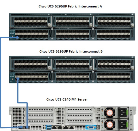
The Cisco UCS C240 M4 rack server is equipped with Intel Xeon E5-2680 v4 processors, 256 GB of memory, Cisco UCS Virtual Interface Card 1227, Cisco 12-Gbps SAS Modular Raid Controller with 2-GB FBWC, 24 1.8-TB 10K SFF SAS drives, 2 240-GB SATA SSD for Boot.
Figure 10 illustrates the port connectivity between the Fabric Interconnect, and Cisco UCS C240 M4 server. Sixteen Cisco UCS C240 M4 servers are used in Master rack configurations.
Figure 10 Fabric Topology for C240 M4
For more information on physical connectivity and single-wire management see:
For more information on physical connectivity illustrations and cluster setup, see:
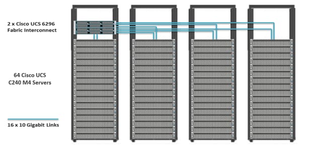
Figure 11 depicts a 64-node cluster. Every rack has 16 Cisco UCS C240 M4 servers. Each link in the figure represents 16 x 10 Gigabit Ethernet link from each of the 16 servers connecting to a Fabric Interconnect as a Direct Connect. Every server is connected to both Fabric Interconnect represented with dual link.
Figure 11 64 Nodes Cluster Configuration
Software Distributions and Versions
The software distributions required versions are listed below.
IBM BigInsights with Apache Hadoop
For more information visit https://www.ibm.com/support/knowledgecenter/en/SSPT3X_4.1.0/com.ibm.swg.im.infosphere.biginsights.welcome.doc/doc/welcome.html.
Red Hat Enterprise Linux (RHEL)
The operating system supported is Red Hat Enterprise Linux 7.2. For more information visit http://www.redhat.com.
Software Versions
The software versions tested and validated in this document are shown in Table 3 .
| Layer |
Component |
Version or Release |
| Compute |
Cisco UCS C240-M4 |
Cisco C240M4.2.0.10c |
| Network |
Cisco UCS 6296UP |
Cisco UCS 3.1(1g) A |
| Cisco UCS VIC1227 Firmware |
4.1.1(d) |
|
| Cisco UCS VIC1227 Driver |
2.3.0.20 |
|
| Storage |
LSI SAS 3108 |
24.9.1-0011 |
|
|
LSI MegaRAID SAS Driver |
06.810.10.00 |
| Software |
Red Hat Enterprise Linux Server |
7.2 (x86_64) |
| Cisco UCS Manager |
3.1(1g) |
|
| IBM BigInsights with Apache Hadoop |
4.2.0 |
![]() The latest drivers can be downloaded from the link below:
The latest drivers can be downloaded from the link below:
https://software.cisco.com/download/release.html?mdfid=283862063&flowid=25886&softwareid=283853158&release=1.5.7d&relind=AVAILABLE&rellifecycle=&reltype=latest
![]() The Latest Supported RAID controller Driver is already included with the RHEL 7.2 operating system
The Latest Supported RAID controller Driver is already included with the RHEL 7.2 operating system
![]() Cisco C240 M4 Rack Servers with Broadwell (E5 -2600 v4) CPUs are supported from UCS firmware 3.1(1g) onwards.
Cisco C240 M4 Rack Servers with Broadwell (E5 -2600 v4) CPUs are supported from UCS firmware 3.1(1g) onwards.
Fabric Configuration
This section provides details for configuring a fully redundant, highly available Cisco UCS 6296 fabric configuration.
· Initial setup of the Fabric Interconnect A and B.
· Connect to Cisco UCS Manager using virtual IP address of using the web browser.
· Launch Cisco UCS Manager.
· Enable server, uplink and appliance ports.
· Start discovery process.
· Create pools and polices for service profile template.
· Create Service Profile template and 64 Service profiles.
· Associate Service Profiles to servers.
Performing Initial Setup of Cisco UCS 6296 Fabric Interconnects
This section describes the initial setup of the Cisco UCS 6296 Fabric Interconnects A and B.
Configure Fabric Interconnect A
1. Connect to the console port on the first Cisco UCS 6296 Fabric Interconnect.
2. At the prompt to enter the configuration method, enter console to continue.
3. If asked to either perform a new setup or restore from backup, enter setup to continue.
4. Enter y to continue to set up a new Fabric Interconnect.
5. Enter y to enforce strong passwords.
6. Enter the password for the admin user.
7. Enter the same password again to confirm the password for the admin user.
8. When asked if this fabric interconnect is part of a cluster, answer y to continue.
9. Enter A for the switch fabric.
10. Enter the cluster name for the system name.
11. Enter the Mgmt0 IPv4 address.
12. Enter the Mgmt0 IPv4 netmask.
13. Enter the IPv4 address of the default gateway.
14. Enter the cluster IPv4 address.
15. To configure DNS, answer y.
16. Enter the DNS IPv4 address.
17. Answer y to set up the default domain name.
18. Enter the default domain name.
19. Review the settings that were printed to the console, and if they are correct, answer yes to save the configuration.
20. Wait for the login prompt to make sure the configuration has been saved.
Configure Fabric Interconnect B
1. Connect to the console port on the second Cisco UCS 6296 Fabric Interconnect.
2. When prompted to enter the configuration method, enter console to continue.
3. The installer detects the presence of the partner Fabric Interconnect and adds this fabric interconnect to the cluster. Enter y to continue the installation.
4. Enter the admin password that was configured for the first Fabric Interconnect.
5. Enter the Mgmt0 IPv4 address.
6. Answer yes to save the configuration.
7. Wait for the login prompt to confirm that the configuration has been saved.
For more information on configuring Cisco UCS 6200 Series Fabric Interconnect, see: http://www.cisco.com/en/US/docs/unified_computing/ucs/sw/gui/config/guide/2.0/b_UCSM_GUI_Configuration_Guide_2_0_chapter_0100.html.
Logging Into Cisco UCS Manager
To login to Cisco UCS Manager, complete the following steps:
1. Open a Web browser and navigate to the Cisco UCS 6296 Fabric Interconnect cluster address.
2. Click the Launch link to download the Cisco UCS Manager software.
3. If prompted to accept security certificates, accept as necessary.
4. When prompted, enter admin for the username and enter the administrative password.
5. Click Login to log in to the Cisco UCS Manager.
Upgrading UCSM Software to Version 3.1(1g)
This document assumes the use of Cisco UCS 3.1(1g). Refer to Cisco UCS 3.1 Release (to upgrade the Cisco UCS Manager software and Cisco UCS 6296 Fabric Interconnect software to version 3.1(1g). Also, make sure the Cisco UCS C-Series version 3.1(1g) software bundle is installed on the Fabric Interconnects.
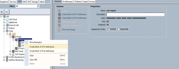
Adding a Block of IP Addresses for KVM Access
To create a block of KVM IP addresses for server access in the Cisco UCS environment, complete the following steps, as shown in Figure 12:
1. Select the LAN tab at the top of the left window.
2. Select Pools > IpPools > Ip Pool ext-mgmt.
3. Right-click IP Pool ext-mgmt.
4. Select Create Block of IPv4 Addresses.
Figure 12 Adding a Block of IPv4 Addresses for KVM Access Part 1
5. Enter the starting IP address of the block and number of IPs needed, as well as the subnet and gateway information (Figure 13).
Figure 13 Adding a Block of IPv4 Addresses for KVM Access Part 2
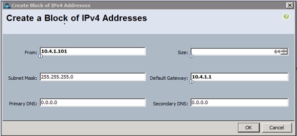
6. Click OK to create the IP block.
7. Click OK in the message box.
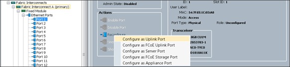
Enabling Uplink Ports
To enable uplinks ports, complete the following steps as shown in Figure 14:
1. Select the Equipment tab on the top left of the window.
2. Select Equipment > Fabric Interconnects > Fabric Interconnect A (primary) > Fixed Module.
3. Expand the Unconfigured Ethernet Ports section.
4. Select port 1 that is connected to the uplink switch, right-click, then select Reconfigure > Configure as Uplink Port.
5. Select Show Interface and select 10GB for Uplink Connection.
6. A pop-up window appears to confirm the selection. Click Yes then OK to continue.
7. Select Equipment > Fabric Interconnects > Fabric Interconnect B (subordinate) > Fixed Module.
8. Expand the Unconfigured Ethernet Ports section.
9. Select port number 1, which is connected to the uplink switch, right-click, then select Reconfigure > Configure as Uplink Port.
10. Select Show Interface and select 10GB for Uplink Connection.
11. A pop-up window appears to confirm the selection. Click Yes then OK to continue.
Figure 14 Enabling Uplink Ports
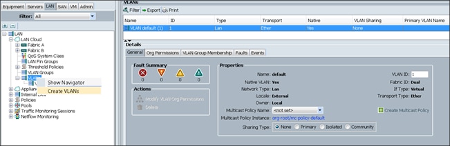
Configuring VLANs
VLANs are configured as in shown in Table 4 .
| VLAN |
NIC Port |
Function |
| VLAN19 |
eth0 |
Data |
The NIC will carry the data traffic from VLAN19. A single vNIC is used in this configuration and the Fabric Failover feature in Fabric Interconnects will take care of any physical port down issues. It will be a seamless transition from an application perspective.
To configure VLANs in the Cisco UCS Manager GUI, complete the following steps as shown in Figure 15:
1. Select the LAN tab in the left pane in the Cisco UCSM GUI.
2. Select LAN > LAN Cloud > VLANs.
3. Right-click the VLANs under the root organization.
4. Select Create VLANs to create the VLAN.
5. Enter vlan19 for the VLAN Name (Figure 16).
6. Keep multicast policy as <not set>.
7. Select Common/Global for vlan19.
8. Enter 19 in the VLAN IDs field for the Create VLAN IDs.
9. Click OK and then, click Finish.
10. Click OK in the success message box.
Figure 16 Creating a VLAN for DATA
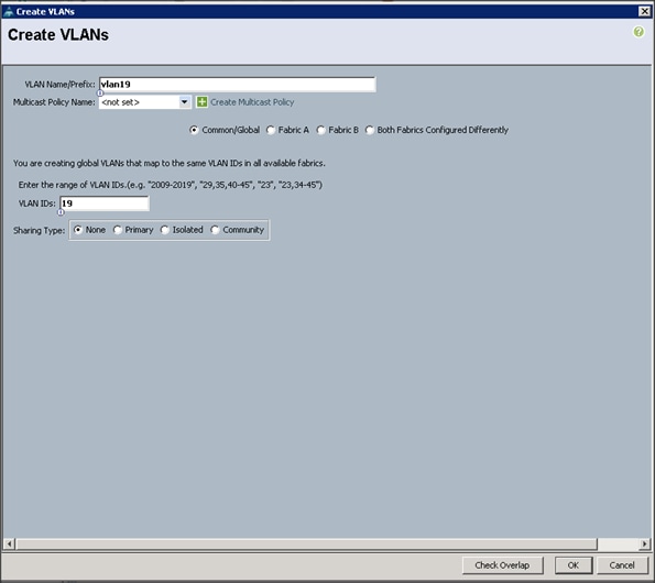
11. Click OK and then, click Finish.
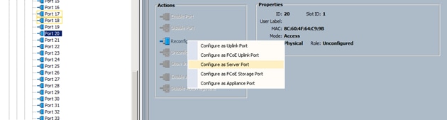
Enabling Server Ports
To enable server ports, complete the following steps:
1. Select the Equipment tab on the top left of the window (Figure 17).
2. Select Equipment > Fabric Interconnects > Fabric Interconnect A (primary) > Fixed Module.
3. Expand the Unconfigured Ethernet Ports section.
4. Select all the ports that are connected to the Servers right-click them, and select Reconfigure > Configure as a Server Port.
5. A pop-up window appears to confirm the selection. Click Yes then OK to continue.
6. Select Equipment > Fabric Interconnects > Fabric Interconnect B (subordinate) > Fixed Module.
7. Expand the Unconfigured Ethernet Ports section.
8. Select all the ports that are connected to the Servers right-click them, and select Reconfigure > Configure as a Server Port.
9. A pop-up window appears to confirm the selection. Click Yes, then OK to continue.
Figure 17 Enabling Server Ports
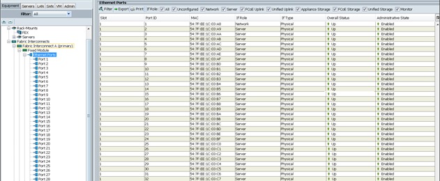
After the Server Discovery, Port 1 will be a Network Port and 2-65 will be Server Ports (Figure 18).
Creating Pools for Service Profile Templates
Creating an Organization
Organizations are used as a means to arrange and restrict access to various groups within the IT organization, thereby enabling multi-tenancy of the compute resources. This document does not assume the use of Organizations; however the necessary steps are provided for future reference.
To configure an organization within the Cisco UCS Manager GUI, complete the following steps:
1. Click New on the top left corner in the right pane in the Cisco UCS Manager GUI.
2. Select Create Organization from the options
3. Enter a name for the organization.
4. (Optional) Enter a description for the organization.
5. Click OK.
6. Click OK in the success message box.
Creating MAC Address Pools
To create MAC address pools, complete the following steps (Figure 19):
1. Select the LAN tab on the left of the window.
2. Select Pools > root.
3. Right-click MAC Pools under the root organization.
4. Select Create MAC Pool to create the MAC address pool. Enter ucs for the name of the MAC pool.
5. (Optional) Enter a description of the MAC pool.
6. Select Assignment Order Sequential.
7. Click Next.
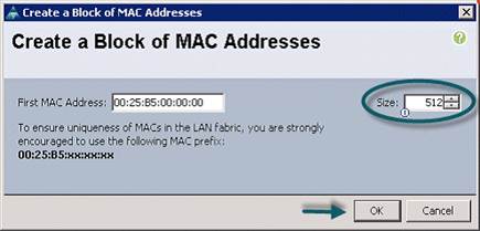
8. Click Add.
9. Specify a starting MAC address (Figure 20).
10. Specify a size of the MAC address pool, which is sufficient to support the available server resources.
11. Click OK.
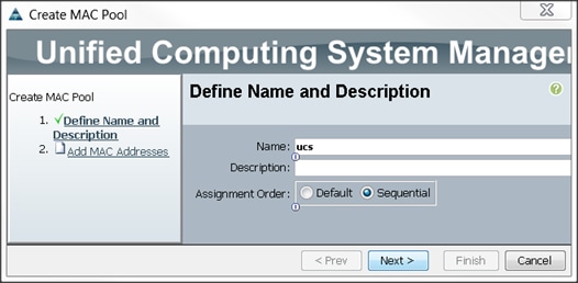
Figure 20 Specifying First MAC Address and Size
12. Click Finish (Figure 21).
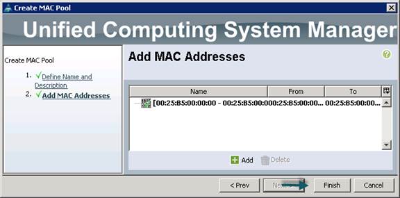
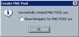
13. When the message box displays, click OK (Figure 22).
Creating a Server Pool
A server pool contains a set of servers. These servers typically share the same characteristics. Those characteristics can be their location in the chassis, or an attribute such as server type, amount of memory, local storage, type of CPU, or local drive configuration. A server can be manually assigned to a server pool, or server pool policies and server pool policy qualifications can be used to automate the assignment.
To configure the server pool within the Cisco UCS Manager GUI, complete the following steps:
1. Select the Servers tab in the left pane in the Cisco UCS Manager GUI.
2. Select Pools > root.
3. Right-click the Server Pools.
4. Select Create Server Pool.
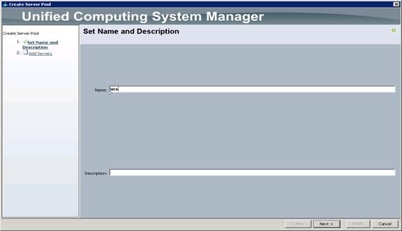
5. Enter the required name (ucs) for the Server Pool in the name text box (Figure 23).
6. (Optional) enter a description for the organization.
7. Click Next > to add the servers.
Figure 23 Unified Computing System/Set Name and Description
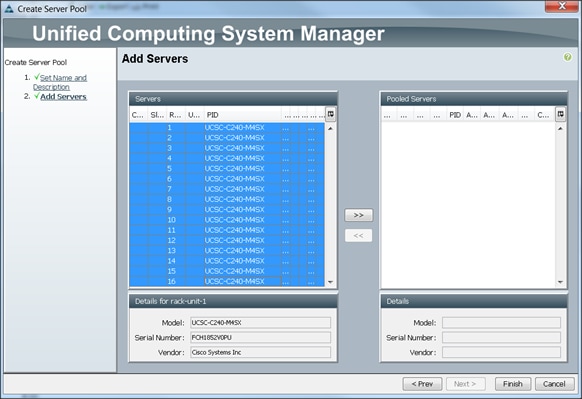
8. Select all the Cisco UCS C240M4SX servers to be added to the server pool that was previously created (ucs), then Click >> to add them to the pool (Figure 24).
9. Click Finish.
10. Click OK and then click Finish.
Creating Policies for Service Profile Templates
Creating Host Firmware Package Policy
Firmware management policies allow the administrator to select the corresponding packages for a given server configuration. These include adapters, BIOS, board controllers, FC adapters, HBA options, and storage controller properties as applicable.
To create a firmware management policy for a given server configuration using the Cisco UCS Manager GUI, complete the following steps:
1. Select the Servers tab in the left pane in the Cisco UCS Manager GUI.
2. Select Policies > root.
3. Right-click Host Firmware Packages.
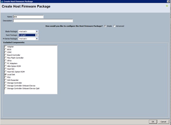
4. Select Create Host Firmware Package (Figure 25).
5. Enter the required Host Firmware package name (ucs).
6. Select Simple radio button to configure the Host Firmware package.
7. Select the appropriate Rack package that has been installed.
8. Click OK to complete creating the management firmware package
9. Click OK.
Figure 25 Create Host Firmware Package
Creating QoS Policies
To create the QoS policy for a given server configuration using the Cisco UCS Manager GUI, complete the following steps:
Platinum Policy
1. Select the LAN tab in the left pane in the Cisco UCS Manager GUI (Figure 26).
2. Select Policies > root.
3. Right-click QoS Policies.
4. Select Create QoS Policy.
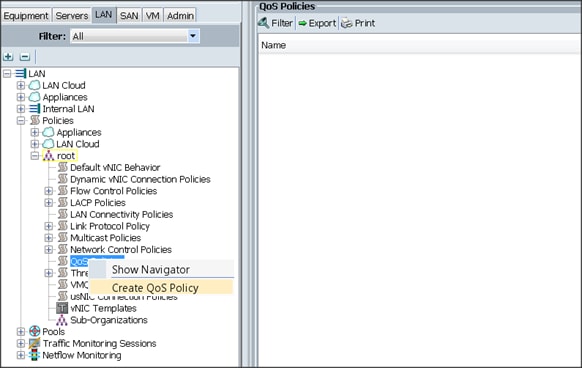
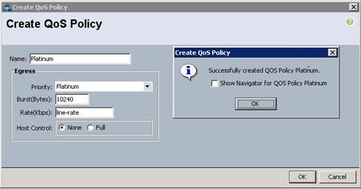
5. Enter Platinum as the name of the policy.
6. Select Platinum from the drop down menu.
7. Keep the Burst(Bytes) field set to default (10240).
8. Keep the Rate(Kbps) field set to default (line-rate).
9. Keep Host Control radio button set to default (none).
10. Once the pop-up window appears, click OK to complete the creation of the Policy (Figure 27).
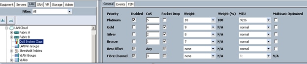
Setting Jumbo Frames
To set Jumbo frames and enable QoS, complete the following steps:
1. Select the LAN tab in the left pane in the Cisco UCSM GUI.
2. Select LAN Cloud > QoS System Class (Figure 28).
3. In the right pane, select the General tab.
4. In the Platinum row, enter 9216 for MTU.
5. Check the Enabled Check box next to Platinum.
6. In the Best Effort row, select none for weight.
7. In the Fiber Channel row, select none for weight.
8. Click Save Changes.
9. Click OK.
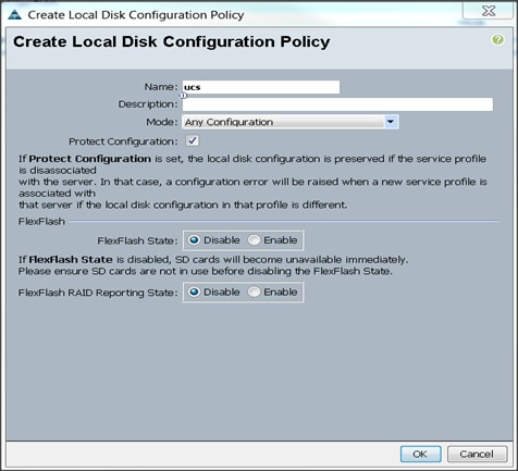
Creating the Local Disk Configuration Policy
To create a local disk configuration policy in the Cisco UCS Manager GUI, complete the following steps:
1. Select the Servers tab on the left pane in the Cisco UCS Manager GUI.
2. Go to Policies > root.
3. Right-click Local Disk Config Policies.
4. Select Create Local Disk Configuration Policy.
5. Enter ucs as the local disk configuration policy name (Figure 29).
6. Change the Mode to Any Configuration. Check the Protect Configuration box.
7. Keep the FlexFlash State field as default (Disable).
8. Keep the FlexFlash RAID Reporting State field as default (Disable).
9. Click OK to complete the creation of the Local Disk Configuration Policy.
10. Click OK.
Figure 29 Create Local Disk Configuration Policy
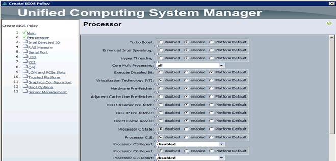
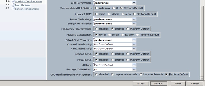
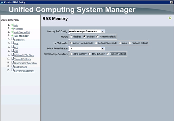
Creating Server BIOS Policy
The BIOS policy feature in Cisco UCS automates the BIOS configuration process. The traditional method of setting the BIOS is manually, and is often error-prone. By creating a BIOS policy and assigning the policy to a server or group of servers, can enable transparency within the BIOS settings configuration.
![]() Note: BIOS settings can have a significant performance impact, depending on the workload and the applications. The BIOS settings listed in this section is for configurations optimized for best performance which can be adjusted based on the application, performance, and energy efficiency requirements.
Note: BIOS settings can have a significant performance impact, depending on the workload and the applications. The BIOS settings listed in this section is for configurations optimized for best performance which can be adjusted based on the application, performance, and energy efficiency requirements.
To create a server BIOS policy using the Cisco UCS Manager GUI, complete the following steps:
1. Select the Servers tab in the left pane in the Cisco UCS Manager GUI.
2. Select Policies > root.
3. Right-click BIOS Policies.
4. Select Create BIOS Policy.
5. Enter the preferred BIOS policy name (ucs).
6. Change the BIOS settings as shown in Figure 30.
7. Changes only need to be made in the Processor and RAS Memory settings (Figure 31).
Figure 30 Cisco Unified Computing System Manager (UCSM)
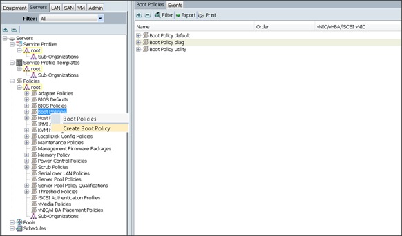
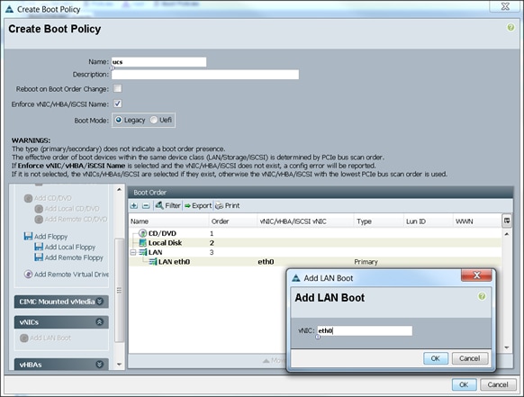
Creating the Boot Policy
To create boot policies within the Cisco UCS Manager GUI, complete the following steps:
1. Select the Servers tab in the left pane in the Cisco UCS Manager GUI.
2. Select Policies > root.
3. Right-click the Boot Policies.
4. Select Create Boot Policy (Figure 32).
5. Enter ucs for the boot policy name.
6. (Optional) enter a description for the boot policy.
7. Keep the Reboot on Boot Order Change check box unchecked.
8. Keep Enforce vNIC/vHBA/iSCSI Name check box checked.
9. Keep Boot Mode Default (Legacy).
10. Expand Local Devices > Add CD/DVD and select Add Local CD/DVD.
11. Expand Local Devices and select Add Local Disk.
12. Expand vNICs and select Add LAN Boot and enter eth0.
13. Click OK to add the Boot Policy (Figure 33).
14. Click OK.
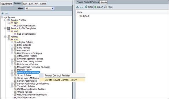
Creating Power Control Policy
To create Power Control policies within the Cisco UCS Manager GUI, complete the following steps:
1. Select the Servers tab in the left pane in the Cisco UCS Manager GUI.
2. Select Policies > root.
3. Right-click the Power Control Policies (Figure 34).
4. Select Create Power Control Policy.
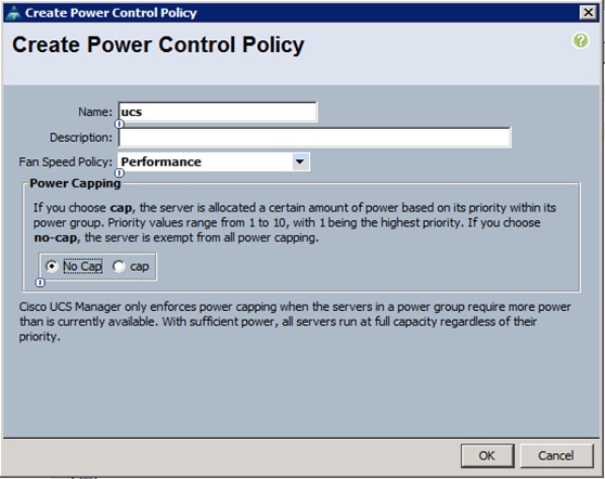
Figure 34 Power Control Policy Events
5. Enter ucs for the Power Control policy name (Figure 35).
6. (Optional) enter a description for the boot policy.
7. Select Performance for Fan Speed Policy.
8. Select No cap for Power Capping selection.
9. Click OK to create the Power Control Policy.
10. Click OK.
Figure 35 Create Power Control Policy
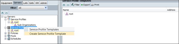
Creating a Service Profile Template
To create a Service Profile Template, complete the following steps:
1. Select the Servers tab in the left pane in the Cisco UCSM GUI.
2. Right-click Service Profile Templates (Figure 36).
3. Select Create Service Profile Template.
Figure 36 Service Profile Template
The Create Service Profile Template window appears.
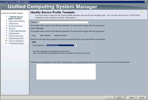
To identify the service profile template, complete the following steps (Figure 37):
4. Name the service profile template ucs. Select the Updating Template radio button.
5. In the UUID section, select Hardware Default as the UUID pool.
6. Click Next to continue to the next section.
Figure 37 Identify Service Profile Template
Configuring the Storage Provisioning for the Template
To configure storage policies, complete the following steps:
1. Go to the Local Disk Configuration Policy tab, and select ucs for the Local Storage (Figure 38).
2. Click Next to continue to the next section.
Figure 38 Storage Provisioning
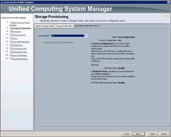
3. Click Next. Once the Networking window appears, go to the next section.
Configuring Network Settings for the Template
1. Keep the Dynamic vNIC Connection Policy field set at the default (Figure 39).
2. Select the Expert radio button for the option, How would you like to configure LAN connectivity?
3. Click Add to add a vNIC to the template.
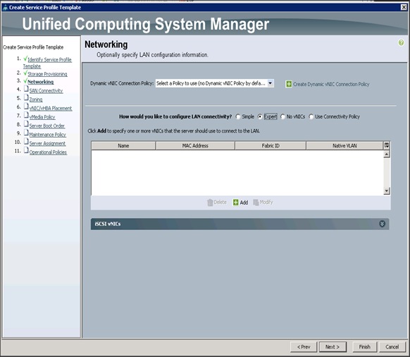
4. The Create vNIC window displays (Figure 40). Name the vNIC eth0.
5. Select ucs in the Mac Address Assignment pool.
6. Select the Fabric A radio button and check the Enable failover check box for the Fabric ID.
7. Check the VLAN19 check box for VLANs and select the Native VLAN radio button.
8. Select MTU size 9000.
9. Select the adapter policy Linux.
10. Select the QoS Policy Platinum.
11. Keep the Network Control Policy set to Default.
12. Click OK.
![]() Note: Optionally, to setup Network Bonding on the vNICs for each host for redundancy and increased throughput; see Figure 113 in Appendix 1.
Note: Optionally, to setup Network Bonding on the vNICs for each host for redundancy and increased throughput; see Figure 113 in Appendix 1.
13. Click Next to continue with SAN Connectivity (Figure 41).
14. Select no vHBAs for How would you like to configure SAN Connectivity? (Figure 42)
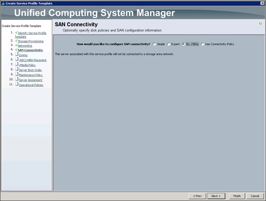
15. Click Next to continue with Zoning (Figure 43).
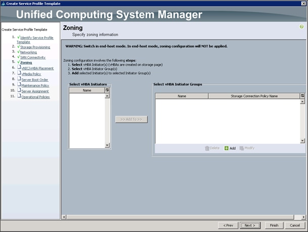
16. Click Next to continue with vNIC/vHBA placement.(Figure 44)
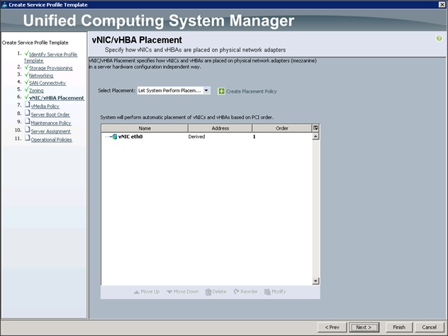
17. Click Next to configure vMedia Policy.
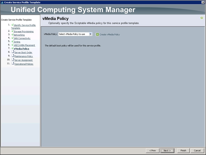
Configuring the vMedia Policy for the Template
1. Click Next once the vMedia Policy window appears to go to the next section.(Figure 45)
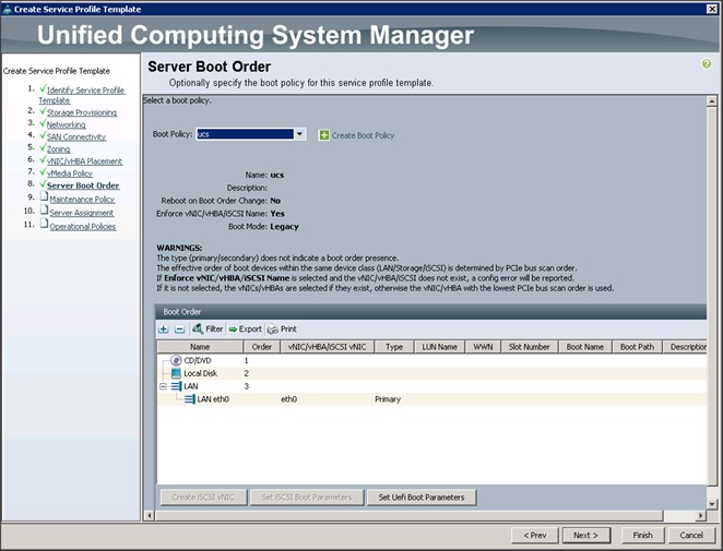
Configuring Server Boot Order for the Template
To set the boot order for the servers, complete the following steps:
1. Select ucs in the Boot Policy name field. (Figure 46)
2. Review to make sure that all of the boot devices were created and identified.
3. Verify that the boot devices are in the correct boot sequence.
4. Click OK.
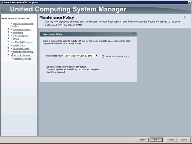
5. Click Next to continue to the next section.
6. In the Maintenance Policy window, apply the maintenance policy (Figure 47).
7. Keep the Maintenance policy at no policy used by default. Click Next to continue to the next section.
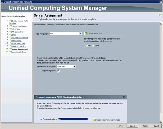
Configuring Server Assignment for the Template
In the Server Assignment window (Figure 48), to assign the servers to the pool, complete the following steps:
1. Select ucs for the Pool Assignment field.
2. Select the power state to be Up.
3. Keep the Server Pool Qualification field set to <not set>.
4. Check the Restrict Migration check box.
5. Select ucs in Host Firmware Package.
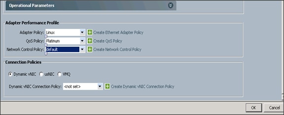
Configuring Operational Policies for the Template
In the Operational Policies Window (Figure 49), complete the following steps:
1. Select ucs in the BIOS Policy field.
2. Select ucs in the Power Control Policy field.
Figure 49 Operational Policies
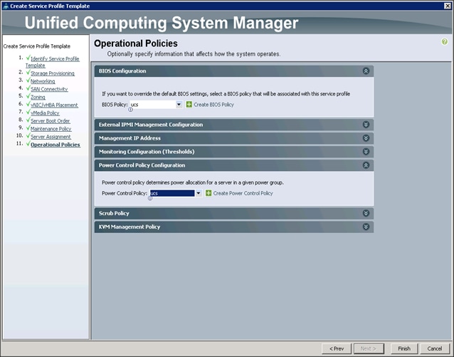
3. Click Finish to create the Service Profile template.
4. Click OK in the pop-up window to proceed.
5. Select the Servers tab in the left pane of the Cisco UCS Manager GUI.
6. Go to Service Profile Templates > root.
7. Right-click Service Profile Templates ucs.
8. Select Create Service Profiles From Template. (Figure 50)
Figure 50 Create Service Profiles From Template
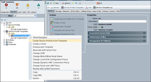
Figure 51 Service Profile Name
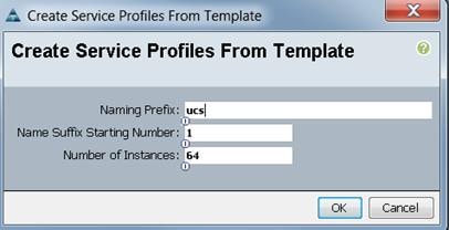
Association of the Service Profiles will take place automatically. Click OK. (Figure 51)
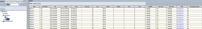
The final Cisco UCS Manager window is shown below in Figure 52.
Figure 52 Cisco UCS Manager window
Installing Red Hat Enterprise Linux 7.2
The following section provides detailed procedures for installing Red Hat Enterprise Linux 7.2 using Software RAID (OS based Mirroring) on Cisco UCS C240 M4 servers. There are multiple ways to install the Red Hat Linux operating system. The installation procedure described in this deployment guide uses KVM console and virtual media from Cisco UCS Manager.
![]() Note: This requires RHEL 7.2 DVD/ISO for the installation
Note: This requires RHEL 7.2 DVD/ISO for the installation
To install the Red Hat Linux 7.2 operating system, complete the following steps:
1. Log in to the Cisco UCS 6296 Fabric Interconnect and launch the Cisco UCS Manager application.
2. Select the Equipment tab.
3. In the navigation pane expand Rack-Mounts and then Servers.
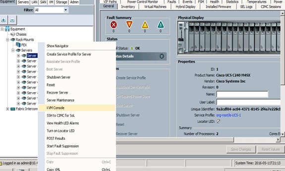
4. Right click on the server and select KVM Console. (Figure 53)
5. In the KVM window, select the Virtual Media tab.
Figure 53 Selecting KVM Console
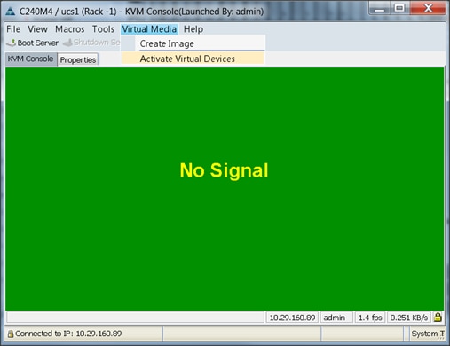
6. Click the Activate Virtual Devices found in Virtual Media tab (Figure 54).
Figure 54 Activate Virtual Devices
7. In the KVM window, select the Virtual Media tab and click the Map CD/DVD (Figure 55).
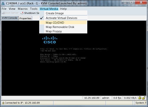
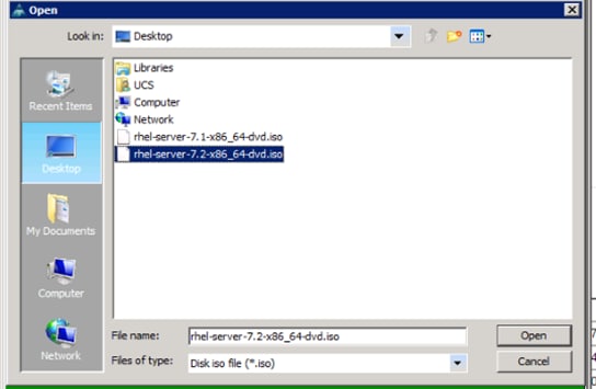
8. Browse to the Red Hat Enterprise Linux Server 7.2 installer ISO image file.
![]() Note: The Red Hat Enterprise Linux 7.2 DVD is assumed to be on the client machine.
Note: The Red Hat Enterprise Linux 7.2 DVD is assumed to be on the client machine.
9. Click Open to add the image to the list of virtual media (Figure 56).
10. In the KVM window, select the KVM tab to monitor during boot.
11. In the KVM window, select the Macros > Static Macros > Ctrl-Alt-Del button in the upper left corner.
12. Click OK.
13. Click OK to reboot the system.
14. On reboot, the machine detects the presence of the Red Hat Enterprise Linux Server 7.2 install media.
15. Select the Install or Upgrade an Existing System.
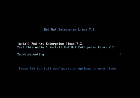
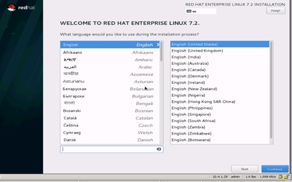
16. Skip the Media test and start the installation. Select the language of installation and click Continue.
Figure 57 Language of Installation
17. Select date and time (Figure 58), which pops up another window as shown below in Figure 58:
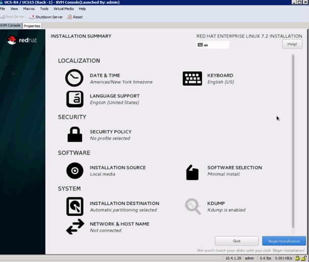
Figure 59 Date and Time Window
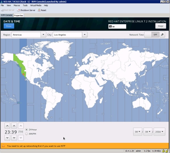
18. Select the location on the map, set the time and click Done.
19. Click on Installation Destination (Figure 60).
Figure 60 Installation Summary Window
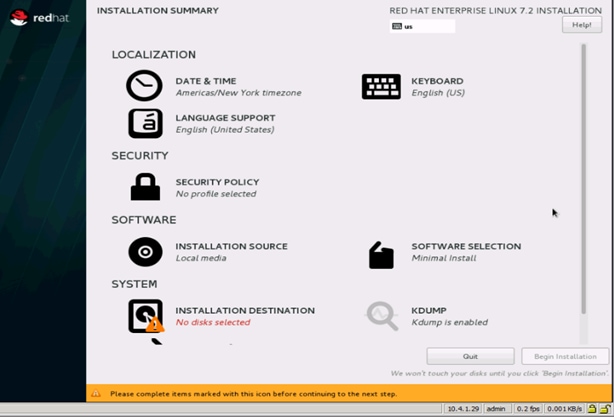
A Caution symbol appears next to Installation Destination as shown in Figure 60 above.
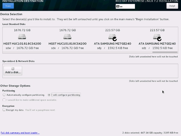
20. This opens a new window with the boot disks (Figure 61).
21. Make the selection, and choose I will configure partitioning. Click Done.
Figure 61 Installation Destination
This opens the new window for creating the partitions (Figure 62).
22. Click on the + sign to add a new partition as shown below, boot partition of size 2048 MB.
23. Click Add MountPoint to add the partition.
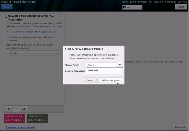
Figure 63 Manual Partitioning/Change Device Type
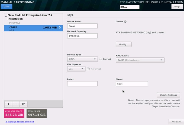
24. Change the Device type to RAID and make sure the RAID Level is RAID1 (Redundancy) and click on Update Settings to save the changes (Figure 63).
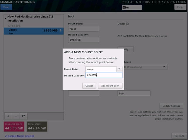
25. Click on the + sign to create the swap partition of size 2048 MB as shown below in Figure 64.
Figure 64 Manual Partitioning/Swap
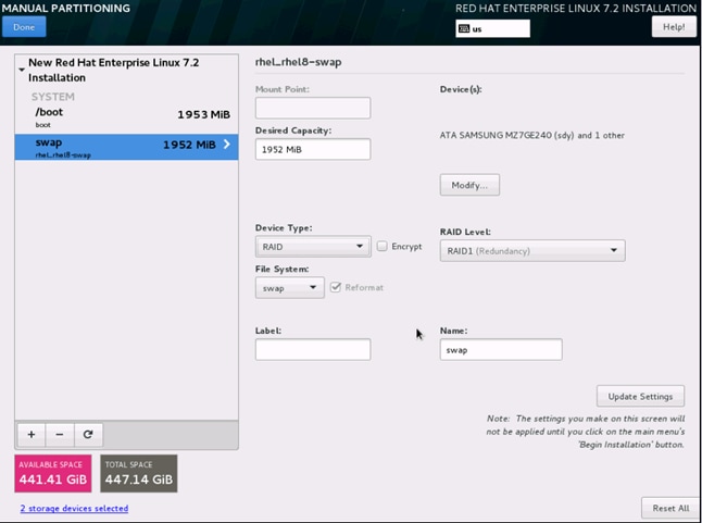
26. Change the Device type to RAID and RAID level to RAID1 (Redundancy) and click on Update Settings.
Figure 65 Manual Partitioning/Swap
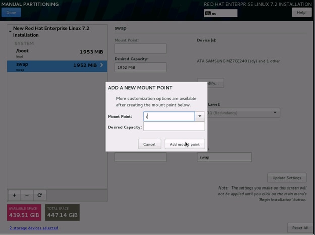
27. Click + to add the / partition (Figure 65). The size can be left empty so it uses the remaining capacity and click Add Mountpoint (Figure 66).
Figure 66 Add A New Mount Point
In the next window (Figure 67):
28. Change the Device type to RAID and RAID level to RAID1 (Redundancy). Click Update Settings.
Figure 67 Partition/Change Device Type to RAID
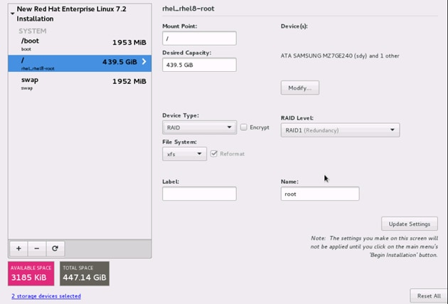
29. Click Done to go back to the main screen and continue the Installation.
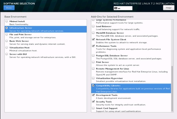
30. Click on Software Selection (Figure 68).
The Software Selection window opens (Figure 69).
31. Select Infrastructure Server and select the Add-ons as noted below. Click Done.
Figure 69 Software Selection Window
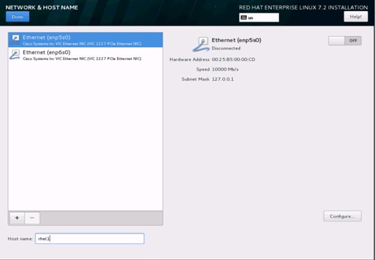
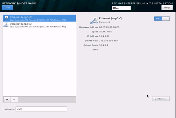
32. Click on Network and Hostname and configure Hostname and Networking for the Host (Figure 70).
Figure 70 Select Network and Host Name
33. Type in the hostname as shown below (Figure 71).
Figure 71 Network and Host Name Window
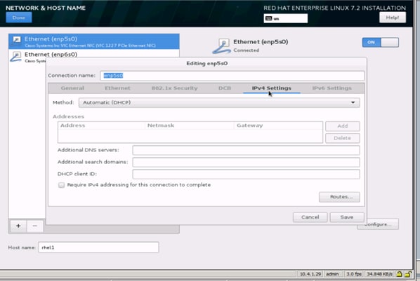
34. Click on Configure to open the Network Connectivity window (Figure 72).
35. Click on IPV4Settings.
Figure 72 Network Connectivity Window
36. Change the Method to Manual and click Add to enter the IP Address, Netmask and Gateway details. (Figure 73)
Figure 73 Add IP Address Details
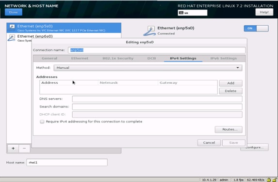
Figure 74 Editing IP Address Details
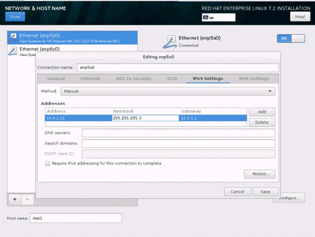
37. Click Save. (Figure 74)
38. Update the Hostname and turn Ethernet On. (Figure 75)
39. Click Done to return to the main menu.
Figure 75 Update the Hostname and Turn Ethernet On
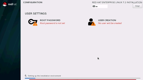
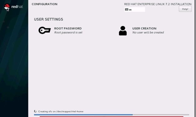
40. Click Begin Installation in the main menu. (Figure 76)
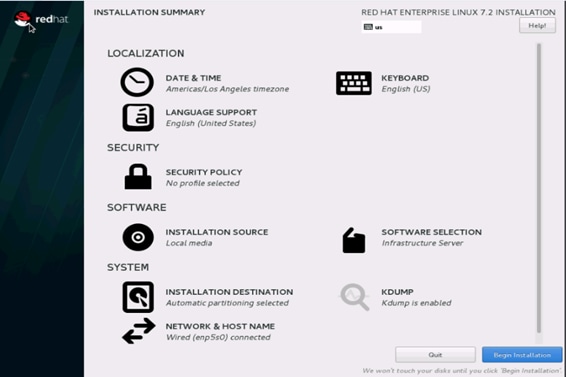
41. Select Root Password in the User Settings. (Figure 77)
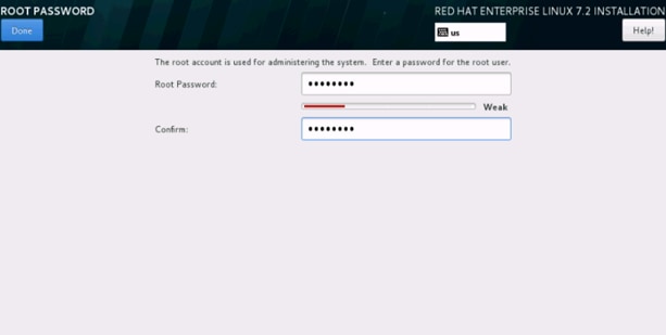
42. Enter the Root Password and click Done. (Figure 78)
A progress window will open (Figure 79).
Figure 79 Installation Progress
43. Once the installation is complete reboot the system.
44. Repeat steps 1 to 42 to install Red Hat Enterprise Linux 7.2 on Servers 2 through 64.
![]() Note: The OS installation and configuration of the nodes that is mentioned above can be automated through PXE boot or third party tools.
Note: The OS installation and configuration of the nodes that is mentioned above can be automated through PXE boot or third party tools.
The hostnames and their corresponding IP addresses are shown in Table 5 .
Table 5 Hostnames and IP Addresses
| Hostname |
eth0 |
| rhel1 |
10.4.1.31 |
| rhel2 |
10.4.1.32 |
| rhel3 |
10.4.1.33 |
| rhel4 |
10.4.1.34 |
| rhel1 |
10.4.1.35 |
| rhel6 |
10.4.1.36 |
| rhel7 |
10.4.1.37 |
| rhel8 |
10.4.1.38 |
| rhel9 |
10.4.1.39 |
| rhel10 |
10.4.1.40 |
| rhel11 |
10.4.1.41 |
| rhel12 |
10.4.1.42 |
| rhel13 |
10.4.1.43 |
| rhel14 |
10.4.1.44 |
| rhel15 |
10.4.1.45 |
| rhel16 |
10.4.1.46 |
| … |
… |
| rhel64 |
10.4.1.94 |
Choose one of the nodes of the cluster or a separate node as the Admin Node for management such as installation, cluster parallel shell, creating a local Red Hat repo and others. In this document, we use rhel1 for this purpose.
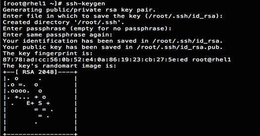
Setting Up Password-less Login
To manage all of the clusters nodes from the admin node password-less login needs to be setup. It assists in automating common tasks with clustershell (clush, a cluster wide parallel shell), and shell-scripts without having to use passwords.
Once Red Hat Linux is installed across all the nodes in the cluster, follow the steps below in order to enable password-less login across all the nodes.
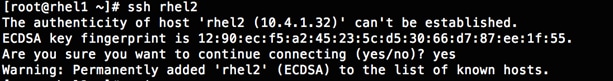
1. Login to the Admin Node (rhel1).
#ssh 10.4.1.31
2. Run the ssh-keygen command to create both public and private keys on the admin node.
3. Then run the following command from the admin node to copy the public key id_rsa.pub to all the nodes of the cluster. ssh-copy-id appends the keys to the remote-host’s .ssh/authorized_keys.
#for IP in {31..94}; do echo -n "$IP -> "; ssh-copy-id -i ~/.ssh/id_rsa.pub 10.4.1.$IP; done
4. Enter yes for Are you sure you want to continue connecting (yes/no)?
5. Enter the password of the remote host.
Configuring /etc/hosts
Setup /etc/hosts on the Admin node; this is a pre-configuration to setup DNS as shown in the next section.
To create the host file on the admin node, complete the following steps:
1. Populate the host file with IP addresses and corresponding hostnames on the Admin node (rhel1) and other nodes as follows:
2. On Admin Node (rhel1)
#vi /etc/hosts
127.0.0.1 localhost localhost.localdomain localhost4 \ localhost4.localdomain4
::1 localhost localhost.localdomain localhost6 \ localhost6.localdomain6
10.4.1.31 rhel1
10.4.1.32 rhel2
10.4.1.33 rhel3
10.4.1.34 rhel4
10.4.1.35 rhel5
10.4.1.36 rhel6
10.4.1.37 rhel7
10.4.1.38 rhel8
10.4.1.39 rhel9
10.4.1.40 rhel10
10.4.1.41 rhel11
10.4.1.42 rhel12
10.4.1.43 rhel13
10.4.1.44 rhel14
10.4.1.45 rhel15
10.4.1.46 rhel16
...
10.4.1.94 rhel64
Creating a Red Hat Enterprise Linux (RHEL) 7.2 Local Repo
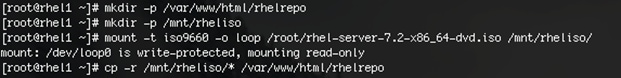
To create a repository using RHEL DVD or ISO on the admin node (in this deployment rhel1 is used for this purpose), create a directory with all the required RPMs, run the createrepo command and then publish the resulting repository.
1. Log on to rhel1. Create a directory that would contain the repository.
#mkdir -p /var/www/html/rhelrepo
2. Copy the contents of the Red Hat DVD to /var/www/html/rhelrepo
3. Alternatively, if access to a Red Hat ISO Image is available, copy the ISO file to rhel1.
4. And login back to rhel1 and create the mount directory.
#scp rhel-server-7.2-x86_64-dvd.iso rhel1:/root/
#mkdir -p /mnt/rheliso
#mount -t iso9660 -o loop /root/rhel-server-7.2-x86_64-dvd.iso /mnt/rheliso/
5. Copy the contents of the ISO to the /var/www/html/rhelrepo directory.
#cp -r /mnt/rheliso/* /var/www/html/rhelrepo
6. Now on rhel1 create a .repo file to enable the use of the yum command.
#vi /var/www/html/rhelrepo/rheliso.repo
[rhel7.2]
name=Red Hat Enterprise Linux 7.2
baseurl=http://10.4.1.31/rhelrepo
gpgcheck=0
enabled=1
7. Now copy rheliso.repo file from /var/www/html/rhelrepo to /etc/yum.repos.d on rhel1.
#cp /var/www/html/rhelrepo/rheliso.repo /etc/yum.repos.d/
![]() Note: Based on this repo file yum requires httpd to be running on rhel1 for other nodes to access the repository.
Note: Based on this repo file yum requires httpd to be running on rhel1 for other nodes to access the repository.
8. To make use of repository files on rhel1 without httpd, edit the baseurl of repo file /etc/yum.repos.d/rheliso.repo to point repository location in the file system.
![]() Note: This step is needed to install software on Admin Node (rhel1) using the repo (such as httpd, create-repo, etc.)
Note: This step is needed to install software on Admin Node (rhel1) using the repo (such as httpd, create-repo, etc.)
#vi /etc/yum.repos.d/rheliso.repo
[rhel7.2]
name=Red Hat Enterprise Linux 7.2
baseurl=file:///var/www/html/rhelrepo
gpgcheck=0
enabled=1
Creating the Red Hat Repository Database
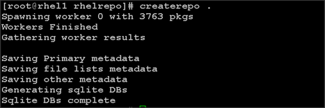
1. Install the createrepo package on admin node (rhel1). Use it to regenerate the repository database(s) for the local copy of the RHEL DVD contents.
#yum -y install createrepo
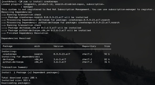
2. Run createrepo on the RHEL repository to create the repo database on admin node
#cd /var/www/html/rhelrepo
#createrepo
Setting up ClusterShell
ClusterShell (or clush) is the cluster-wide shell that runs commands on several hosts in parallel.
1. From the system connected to the Internet download ClusterShell (clush) and install it on rhel1. ClusterShell is available from EPEL (Extra Packages for Enterprise Linux) repository.
#wget http://rpm.pbone.net/index.php3/stat/4/idpl/31529309/dir/redhat_el_7/com/clustershell-1.7-1.el7.noarch.rpm.html
#scp clustershell-1.7-1.el7.noarch.rpm rhel1:/root/
2. Login to rhel1 and install cluster shell.
#yum –y install clustershell-1.71.el7.noarch.rpm
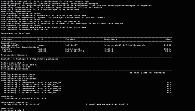
3. Edit /etc/clustershell/groups.d/local.cfg file to include hostnames for all the nodes of the cluster. This set of hosts is taken when running clush with the ‘-a’ option.
4. For 64 node cluster as in our CVD, set groups file as follows,
#vi /etc/clustershell/groups.d/local.cfg
![]()
all: rhel[1-64]
![]() Note: For more information and documentation on ClusterShell, visit https://github.com/cea-hpc/clustershell/wiki/UserAndProgrammingGuide.
Note: For more information and documentation on ClusterShell, visit https://github.com/cea-hpc/clustershell/wiki/UserAndProgrammingGuide.
![]() Note: ClusterShell will not work if not ssh to the machine earlier (as it must be in the known_hosts file), for instance, as in the case below for rhel<host>.
Note: ClusterShell will not work if not ssh to the machine earlier (as it must be in the known_hosts file), for instance, as in the case below for rhel<host>.
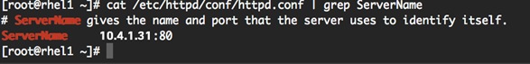
Installing httpd
Setting up RHEL repo on the admin node requires httpd. To set up RHEL repository on the admin node, complete the following steps:
1. Install httpd on the admin node to host repositories.
The Red Hat repository is hosted using HTTP on the admin node, this machine is accessible by all the hosts in the cluster.
#yum –y install httpd
2. Add ServerName and make the necessary changes to the server configuration file.
#vi /etc/httpd/conf/httpd.conf
ServerName 10.4.1.31:80
3. Start httpd
#service httpd start
#chkconfig httpd on
Set Up all Nodes to Use the RHEL Repository
![]() Note: Based on this repo file, yum requires httpd to be running on rhel1 for other nodes to access the repository.
Note: Based on this repo file, yum requires httpd to be running on rhel1 for other nodes to access the repository.
1. Copy the rheliso.repo to all the nodes of the cluster.
#clush –w rhel[2-64] -c /var/www/html/rhelrepo/rheliso.repo --dest=/etc/yum.repos.d/
![]()
2. Also copy the /etc/hosts file to all nodes.
#clush –w rhel[2-64] –c /etc/hosts –-dest=/etc/hosts
3. Purge the yum caches after this
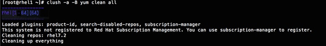
#clush -a -B yum clean all
#clush –a –B yum repolist
![]() Note: While the suggested configuration is to disable SELinux as shown below, if for any reason SELinux needs to be enabled on the cluster, run the following to make sure that httpd is able to read the Yum repofiles.
Note: While the suggested configuration is to disable SELinux as shown below, if for any reason SELinux needs to be enabled on the cluster, run the following to make sure that httpd is able to read the Yum repofiles.
#chcon -R -t httpd_sys_content_t /var/www/html/
Configure DNS
This section details setting up DNS using dnsmasq as an example based on the /etc/hosts configuration setup in the earlier section.
To create the host file across all the nodes in the cluster, complete the following steps:
1. Disable Network manager on all nodes
#clush -a -b service NetworkManager stop
#clush -a -b chkconfig NetworkManager off
2. Update /etc/resolv.conf file to point to Admin Node
#vi /etc/resolv.conf
nameserver 10.4.1.31
![]() Note: This step is needed if setting up dnsmasq on the Admin node. If not this file should be updated with the correct nameserver.
Note: This step is needed if setting up dnsmasq on the Admin node. If not this file should be updated with the correct nameserver.
![]() Note: Alternatively #systemctl start NetworkManager.service can be used to start the service. #systemctl stop NetworkManager.service can be used to stop the service. Use #systemctl disable NetworkManager.service to stop a service from being automatically started at boot time.
Note: Alternatively #systemctl start NetworkManager.service can be used to start the service. #systemctl stop NetworkManager.service can be used to stop the service. Use #systemctl disable NetworkManager.service to stop a service from being automatically started at boot time.
3. Install and Start dnsmasq on Admin node
#service dnsmasq start
#chkconfig dnsmasq on
4. Deploy /etc/resolv.conf from the admin node (rhel1) to all the nodes via the following clush command:
#clush -a -B -c /etc/resolv.conf
![]() Note: A clush copy without –dest copies to the same directory location as the source-file directory.
Note: A clush copy without –dest copies to the same directory location as the source-file directory.
5. Ensure DNS is working fine by running the following command on the Admin node and any data-node:
[root@rhel2 ~]# nslookup rhel1
Server: 10.4.1.31
Address: 10.4.1.31#53
Name: rhel1
Address: 10.4.1.31 ç
![]() Note: yum install –y bind-utils will need to be run for nslookup to utility to run.
Note: yum install –y bind-utils will need to be run for nslookup to utility to run.
Upgrading the Cisco Network driver for VIC1227
The latest Cisco Network driver is required for performance and updates. The latest drivers can be downloaded from the link below:
https://software.cisco.com/download/release.html?mdfid=286281356&reltype=latest&relind=AVAILABLE&dwnld=true&softwareid=283853158&rellifecycle=&atcFlag=N&release=2.0%289b%29&dwldImageGuid=84C2FF3BB579A1BF32F7227C59F6DF886CEDBE99&flowid=71443
1. In the ISO image, the required driver kmod-enic-2.3.0.20-rhel7u2.el7.x86_64.rpm can be located at \Linux\Network\Cisco\VIC\RHEL\RHEL7.2.
2. From a node connected to the Internet, download, extract and transfer kmod-enic-2.3.0.20-rhel7u2.el7.x86_64.rpm to rhel1 (admin node).
3. Install the rpm on all nodes of the cluster using the following clush commands. For this example the rpm is assumed to be in present working directory of rhel1.
[root@rhel1 ~]# clush -a -b -c kmod-enic-2.3.0.20-rhel7u2.el7.x86_64.rpm
[root@rhel1 ~]# clush -a -b "rpm –ivh kmod-enic-2.3.0.20-rhel7u2.el7.x86_64.rpm"
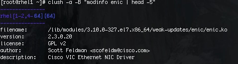
4. Ensure that the above installed version of kmod-enic driver is being used on all nodes by running the command "modinfo enic" on all nodes
[root@rhel1 ~]# clush -a -B "modinfo enic | head -5"
5. Also it is recommended to download the kmod-megaraid driver for higher performance, the RPM can be found in the same package at \Linux\Storage\LSI\Cisco_Storage_12G_SAS_RAID_controller\RHEL\RHEL7.2
Installing xfsprogs
From the admin node rhel1 run the command below to install xfsprogs on all the nodes for the xfs filesystem.
#clush -a -B yum -y install xfsprogs
![]()
NTP Configuration
The Network Time Protocol (NTP) is used to synchronize the time of all the nodes within the cluster. The Network Time Protocol daemon (ntpd) sets and maintains the system time of day in synchronism with the timeserver located in the admin node (rhel1). Configuring NTP is critical for any Hadoop Cluster. If server clocks in the cluster drift out of sync, serious problems will occur with HBase and other services.
#clush –a –b "yum –y install ntp"
|
|
|
1. Configure /etc/ntp.conf on the admin node only with the following contents:
#vi /etc/ntp.conf
driftfile /var/lib/ntp/drift
restrict 127.0.0.1
restrict -6 ::1
server 127.127.1.0
fudge 127.127.1.0 stratum 10
includefile /etc/ntp/crypto/pw
keys /etc/ntp/keys
2. Create /root/ntp.conf on the admin node and copy it to all nodes
#vi /root/ntp.conf
server 10.4.1.31driftfile /var/lib/ntp/drift
restrict 127.0.0.1
restrict -6 ::1
includefile /etc/ntp/crypto/pw
keys /etc/ntp/keys
3. Copy ntp.conf file from the admin node to /etc of all the nodes by executing the following command in the admin node (rhel1)
#for SERVER in {32..94 }; do scp /root/ntp.conf 10.4.1.31 .$SERVER:/etc/ntp.conf; done
![]()
![]() Note: Instead of the above for loop, this could be run as a clush command with "–w"option.
Note: Instead of the above for loop, this could be run as a clush command with "–w"option.
#clush -w rhel[2-64] –b –c /root/ntp.conf --dest=/etc
4. Run the following script to syncronize the time and restart NTP daemon on all nodes.
#clush -a -b "service ntpd stop"
#clush -a -b "ntpdate rhel1"
#clush -a -b "service ntpd start"
5. Ensure restart of NTP daemon across reboots
#clush –a –b "systemctl enable ntpd"
Alternatively, the new Chrony service that is quicker to synchronize clocks in mobile and virtual systems can be installed.
1. Install the Chrony service:
# yum install -y chrony
2. Activate the Chrony service at boot:
# systemctl enable chronyd
3. Start the Chrony service:
# systemctl start chronyd
The Chrony configuration is in the /etc/chrony.conf file, configured similar to /etc/ntp.conf.
Enabling Syslog
Syslog must be enabled on each node to preserve logs regarding killed processes or failed jobs. Modern versions such as syslog-ng and rsyslog are possible, making it more difficult to be sure that a syslog daemon is present. One of the following commands should be used to confirm that the service is properly configured:
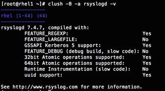
#clush -B -a rsyslogd –v
#clush -B -a service rsyslog status
Setting ulimit
On each node, ulimit -n specifies the number of inodes that can be opened simultaneously. With the default value of 1024, the system appears to be out of disk space and shows no inodes available. This value should be set to 64000 on every node.
Higher values are unlikely to result in an appreciable performance gain.
1. For setting the ulimit on Redhat, edit /etc/security/limits.conf on admin node rhel1 and add the following lines:
root soft nofile 64000
root hard nofile 64000

2. Copy the /etc/security/limits.conf file from admin node (rhel1) to all the nodes using the following command:
#clush -a -b -c /etc/security/limits.conf --dest=/etc/security/
![]()
3. Check that the /etc/pam.d/su file contains the following settings:
#%PAM-1.0
auth sufficient pam_rootOK.so
# Uncomment the following line to implicitly trust users in the "wheel" group.
#auth sufficient pam_wheel.so trust use_uid
# Uncomment the following line to require a user to be in the "wheel" group.
#auth required pam_wheel.so use_uid
auth include system-auth
account sufficient pam_succeed_if.so uid = 0 use_uid quiet
account include system-auth
password include system-auth
session include system-auth
session optional pam_xauth.so
![]() Note: The ulimit values are applied on a new shell, running the command on a node on an earlier instance of a shell will show old values.
Note: The ulimit values are applied on a new shell, running the command on a node on an earlier instance of a shell will show old values.
Disabling SELinux
SELinux must be disabled during the install procedure and cluster setup. SELinux can be enabled after installation and while the cluster is running.
SELinux can be disabled by editing /etc/selinux/config and changing the SELINUX line to SELINUX=disabled. The following command will disable SELINUX on all nodes:
#clush -a -b "sed –i 's/SELINUX=enforcing/SELINUX=disabled/g' /etc/selinux/config"
![]()
#clush –a –b "setenforce 0"
![]() Note: The command above may fail if SELinux is already disabled.
Note: The command above may fail if SELinux is already disabled.
Reboot the machine, if needed for SELinux to be disabled incase it does not take effect. It can checked using
#clush –a –b sestatus
Set TCP Retries
Adjusting the tcp_retries parameter for the system network enables faster detection of failed nodes. Given the advanced networking features of Cisco UCS, this is a safe and recommended change (failures observed at the operating system layer are most likely serious rather than transitory). On each node, setting the number of TCP retries to 5 can help detect unreachable nodes with less latency.
1. Edit the file /etc/sysctl.conf and on admin node rhel1 add the following lines:
net.ipv4.tcp_retries2=5
2. Copy the /etc/sysctl.conf file from admin node (rhel1) to all the nodes using the following command:
#clush -a -b -c /etc/sysctl.conf --dest=/etc/
3. Load the settings from the default sysctl file /etc/sysctl.conf by running.
#clush -B -a sysctl -p
Disabling the Linux Firewall
The default Linux firewall settings are far too restrictive for any Hadoop deployment. Since the Cisco UCS Big Data and Analytics deployment will be in its own isolated network there is no need for that additional firewall.
#clush -a -b " firewall-cmd --zone=public --add-port=80/tcp --permanent"
#clush -a -b "firewall-cmd --reload"
#clush –a –b “systemctl stop firewalld.service”
#clush –a -b “systemctl disable firewalld.service”
Disable Swapping
1. To reduce Swapping, run the following on all nodes. Variable vm.swappiness defines how often swap should be used, 60 is default.
#clush -a -b " echo 'vm.swappiness=1' >> /etc/sysctl.conf"
2. Load the settings from default sysctl file /etc/sysctl.conf.
#clush –a –b "sysctl –p"
Disable Transparent Huge Pages
Disabling Transparent Huge Pages (THP) reduces elevated CPU usage caused by THP.
#clush -a -b "echo never > /sys/kernel/mm/transparent_hugepage/enabled”
#clush -a -b "echo never > /sys/kernel/mm/transparent_hugepage/defrag"
1. The commands above must be run for every reboot, so copy these commands to /etc/rc.local so they are executed automatically for every reboot.
2. On the Admin node, run the following commands:
#rm –f /root/thp_disable
#echo "echo never > /sys/kernel/mm/transparent_hugepage/enabled" >>
/root/thp_disable
#echo "echo never > /sys/kernel/mm/transparent_hugepage/defrag " >>
/root/thp_disable
3. Copy file to each node:
#clush –a –b –c /root/thp_disable
4. Append the content of file thp_disable to /etc/rc.local:
#clush -a -b “cat /root/thp_disable >> /etc/rc.local”
Disable IPv6 Defaults
1. Disable IPv6 as the addresses used are IPv4:
#clush -a -b "echo 'net.ipv6.conf.all.disable_ipv6 = 1' >> /etc/sysctl.conf"
#clush -a -b "echo 'net.ipv6.conf.default.disable_ipv6 = 1' >> /etc/sysctl.conf"
#clush -a -b "echo 'net.ipv6.conf.lo.disable_ipv6 = 1' >> /etc/sysctl.conf"
2. Load the settings from default sysctl file /etc/sysctl.conf:
#clush –a –b "sysctl –p"
Configuring Data Drives on Name Node and Other Management Nodes
This section describes steps to configure non-OS disk drives as RAID1 using StorCli commands as described below. All the drives are going to be part of a single RAID1 volume. This volume can be used for staging any client data to be loaded to HDFS. This volume won’t be used for HDFS data.
1. From the website download storcli: http://www.lsi.com/downloads/Public/RAID%20Controllers/RAID%20Controllers%20Common%20Files/1.14.12_StorCLI.zip
2. Extract the zip file and copy storcli-1.14.12-1.noarch.rpm from the Linux directory.
3. Download storcli and its dependencies and transfer to Admin node.
#scp storcli-1.14.12-1.noarch.rpm rhel1:/root/
4. Copy storcli rpm to all the nodes using the following commands:
#clush -a -b -c /root/storcli-1.14.12-1.noarch.rpm --dest=/root/
5. Run the below command to install storcli on all the nodes.
#clush -a -b “rpm -ivh storcli-1.14.12-1.noarch.rpm”
6. Run the below command to copy storcli64 to root directory.
#cd /opt/MegaRAID/storcli/
#cp storcli64 /root/

7. Copy storcli64 to all the nodes using the following commands:
#clush -a -b -c /root/storcli64 --dest=/root/
8. Run the following script as root user on rhel1 to rhel3 to create the virtual drives for the management nodes.
#vi /root/raid1.sh
./storcli64 -cfgldadd r1[$1:1,$1:2,$1:3,$1:4,$1:5,$1:6,$1:7,$1:8,$1:9,$1:10,$1:11,$1:12,$1:13,$1:14,$1:15,$1:16,$1:17,$1:18,$1:19,$1:20,$1:21,$1:22,$1:23,$1:24] wb ra nocachedbadbbu strpsz1024 -a0
The script above requires enclosure ID as a parameter.
9. Run the following command to get the enclosure id:
#./storcli64 pdlist -a0 | grep Enc | grep -v 252 | awk '{print $4}' | sort | uniq -c | awk '{print $2}'
#chmod 755 raid1.sh
10. Run the MegaCli script as follows:
#./raid1.sh <EnclosureID> obtained by running the command above
WB: Write back
RA: Read Ahead
NoCachedBadBBU: Do not write cache when the BBU is bad.
Strpsz1024: Strip Size of 1024K
![]() Note: The command above will not override existing configurations. To clear and reconfigure existing configurations refer to the Embedded MegaRAID Software Users Guide available at www.lsi.com.
Note: The command above will not override existing configurations. To clear and reconfigure existing configurations refer to the Embedded MegaRAID Software Users Guide available at www.lsi.com.
Configuring Data Drives on Data Nodes
This section describes steps to configure non-OS disk drives as individual RAID0 volumes using StorCli commands as described below. These volumes are going to be used for HDFS Data.
1. Issue the following command from the admin node to create the virtual drives with individual RAID 0 configurations on all the data nodes.
#clush –w rhel[3-64] -B ./storcli64 -cfgeachdskraid0 WB RA direct NoCachedBadBBU strpsz1024 -a0
WB: Write back
RA: Read Ahead
NoCachedBadBBU: Do not write cache when the BBU is bad.
Strpsz1024: Strip Size of 1024K
![]() Note: The command above will not override existing configurations. To clear and reconfigure existing configurations refer to the Embedded MegaRAID Software Users Guide available at www.lsi.com.
Note: The command above will not override existing configurations. To clear and reconfigure existing configurations refer to the Embedded MegaRAID Software Users Guide available at www.lsi.com.
Configuring the Filesystem for NameNodes and DataNodes
The following script will format and mount the available volumes on each node whether it is a Namenode or a Datanode. OS boot partition is going to be skipped. All drives are going to be mounted based on their UUID as /data/disk1, /data/disk2, and so on.
1. On the Admin node, create a file containing the following script.
2. To create partition tables and file systems on the local disks supplied to each of the nodes, run the following script as the root user on each node.
![]() Note: The script assumes there are no partitions already existing on the data volumes. If there are partitions, delete them before running the script. This process is documented in the "Note" section at the end of the section.
Note: The script assumes there are no partitions already existing on the data volumes. If there are partitions, delete them before running the script. This process is documented in the "Note" section at the end of the section.
#vi /root/driveconf.sh
#!/bin/bash
#disks_count=`lsblk -id | grep sd | wc -l`
#if [ $disks_count -eq 24 ]; then
# echo "Found 24 disks"
#else
# echo "Found $disks_count disks. Expecting 24. Exiting.."
# exit 1
#fi
[[ "-x" == "${1}" ]] && set -x && set -v && shift 1
count=1
for X in /sys/class/scsi_host/host?/scan
do
echo '- - -' > ${X}
done
for X in /dev/sd?
do
echo "========"
echo $X
echo "========"
if [[ -b ${X} && `/sbin/parted -s ${X} print quit|/bin/grep -c boot` -ne 0
]]
then
echo "$X bootable - skipping."
continue
else
Y=${X##*/}1
echo "Formatting and Mounting Drive => ${X}"
/sbin/mkfs.xfs -f ${X}
(( $? )) && continue
#Identify UUID
UUID=`blkid ${X} | cut -d " " -f2 | cut -d "=" -f2 | sed 's/"//g'`
/bin/mkdir -p /data/disk${count}
(( $? )) && continue
echo "UUID of ${X} = ${UUID}, mounting ${X} using UUID on /data/disk${count}"
/bin/mount -t xfs -o inode64,noatime,nobarrier -U ${UUID} /data/disk${count}
(( $? )) && continue
echo "UUID=${UUID} /data/disk${count} xfs inode64,noatime,nobarrier 0 0" >> /etc/fstab
((count++))
fi
done
3. Run the following command to copy driveconf.sh to all the nodes:
#chmod 755 /root/driveconf.sh
#clush –a -B –c /root/driveconf.sh
4. Run the following command from the admin node to run the script across all data nodes:
#clush –a –B /root/driveconf.sh
5. Run the following from the admin node to list the partitions and mount points:
#clush –a -B df –h
#clush –a -B mount
#clush –a -B cat /etc/fstab
![]() Note: In-case there is a need to delete any partitions, it can be done so using the following.
Note: In-case there is a need to delete any partitions, it can be done so using the following.
6. Run the mount command (‘mount’) to identify which drive is mounted to which device /dev/sd<?>
7. umount the drive for which partition is to be deleted and run fdisk to delete as shown below.
![]() Note: Care should be taken not to delete the OS partition as this will wipe out the OS.
Note: Care should be taken not to delete the OS partition as this will wipe out the OS.
#mount
#umount /data/disk1 ç (disk1 shown as example)
#(echo d; echo w;) | sudo fdisk /dev/sd<?>
Cluster Verification
This section describes the steps to create the script cluster_verification.sh that helps to verify the CPU, memory, NIC, and storage adapter settings across the cluster on all nodes. This script also checks additional prerequisites such as NTP status, SELinux status, ulimit settings, JAVA_HOME settings and JDK version, IP address and hostname resolution, Linux version and firewall settings.
1. Create the script cluster_verification.sh as shown, on the Admin node (rhel1).
#vi cluster_verification.sh
#!/bin/bash
#shopt -s expand_aliases,
# Setting Color codes
green='\e[0;32m'
red='\e[0;31m'
NC='\e[0m' # No Color
echo -e "${green} === Cisco UCS Integrated Infrastructure for Big Data and Analytics \ Cluster Verification === ${NC}"
echo ""
echo ""
echo -e "${green} ==== System Information ==== ${NC}"
echo ""
echo ""
echo -e "${green}System ${NC}"
clush -a -B " `which dmidecode` |grep -A2 '^System Information'"
echo ""
echo ""
echo -e "${green}BIOS ${NC}"
clush -a -B " `which dmidecode` | grep -A3 '^BIOS I'"
echo ""
echo ""
echo -e "${green}Memory ${NC}"
clush -a -B "cat /proc/meminfo | grep -i ^memt | uniq"
echo ""
echo ""
echo -e "${green}Number of Dimms ${NC}"
clush -a -B "echo -n 'DIMM slots: '; dmidecode |grep -c \ '^[[:space:]]*Locator:'"
clush -a -B "echo -n 'DIMM count is: '; dmidecode | grep \Size| grep -c "MB""
clush -a -B " dmidecode | awk '/Memory Device$/,/^$/ {print}' |\grep -e '^Mem' -e Size: -e Speed: -e Part | sort -u | grep -v -e 'NO \ DIMM' -e 'No Module Installed' -e Unknown"
echo ""
echo ""
# probe for cpu info #
echo -e "${green}CPU ${NC}"
clush -a -B "grep '^model name' /proc/cpuinfo | sort -u"
echo ""
clush -a -B "`which lscpu` | grep -v -e op-mode -e ^Vendor -e family -e\ Model: -e Stepping: -e BogoMIPS -e Virtual -e ^Byte -e '^NUMA node(s)'"
echo ""
echo ""
# probe for nic info #
echo -e "${green}NIC ${NC}"
clush -a -B "ls /sys/class/net | grep ^enp | \xargs -l `which ethtool` | grep -e ^Settings -e Speed"
echo ""
clush -a -B "`which lspci` | grep -i ether"
echo ""
echo ""
# probe for disk info #
echo -e "${green}Storage ${NC}"
clush -a -B "echo 'Storage Controller: '; `which lspci` | grep -i -e \ raid -e storage -e lsi"
echo ""
clush -a -B "dmesg | grep -i raid | grep -i scsi"
echo ""
clush -a -B "lsblk -id | awk '{print \$1,\$4}'|sort | nl"
echo ""
echo ""
echo -e "${green} ================ Software ======================= ${NC}"
echo ""
echo ""
echo -e "${green}Linux Release ${NC}"
clush -a -B "cat /etc/*release | uniq"
echo ""
echo ""
echo -e "${green}Linux Version ${NC}"
clush -a -B "uname -srvm | fmt"
echo ""
echo ""
echo -e "${green}Date ${NC}"
clush -a -B date
echo ""
echo ""
echo -e "${green}NTP Status ${NC}"
clush -a -B "ntpstat 2>&1 | head -1"
echo ""
echo ""
echo -e "${green}SELINUX ${NC}"
clush -a -B "echo -n 'SElinux status: '; grep ^SELINUX= \/etc/selinux/config 2>&1"
echo ""
echo ""
clush -a -B "echo -n 'CPUspeed Service: '; cpupower frequency-info \ status 2>&1"
#clush -a -B "echo -n 'CPUspeed Service: '; `which chkconfig` --list \ cpuspeed 2>&1"
echo ""
echo ""
echo -e "${green}Java Version${NC}"
clush -a -B 'java -version 2>&1; echo JAVA_HOME is ${JAVA_HOME:-Not \ De-fined!}'
echo ""
echo ""
echo -e "${green}Hostname LoOKup${NC}"
clush -a -B " ip addr show"
echo ""
echo ""
echo -e "${green}Open File Limit${NC}"
clush -a -B 'echo -n "Open file limit(should be >32K): "; ulimit -n'
# MapR related RPMs
clush -a -B 'rpm -qa | grep -i nfs |sort'
clush -a -B 'rpm -qa | grep -i nfs |sort'
clush -a -B 'echo Missing RPMs: ; for each in make patch redhat-lsb irqbalance syslinux hdparm sdparm dmidecode nc; do rpm -q $each | grep "is not installed"; done'
clush -a -B "ls -d /opt/mapr/* | head"
# mapr login for hadoop
clush -a -B 'echo "mapr login for Hadoop "; getent passwd mapr'
clush -a -B 'echo "Root login "; getent passwd root'
exit
![]() NOTE: Please install pciutils if not installed, to run the script correctly.
NOTE: Please install pciutils if not installed, to run the script correctly.
2. Change permissions to executable.
chmod 755 cluster_verification.sh
3. Run the Cluster Verification tool from the admin node. This can be run before starting Hadoop to identify any discrepancies in Post OS Configuration between the servers or during troubleshooting of any cluster / Hadoop issues.
#./cluster_verification.sh
IBM BigInsights provides the power of open source, IBM innovations and rich developer tools – and puts the full range of analytics for Hadoop, Spark, and SQL into the hands of big data analytics teams. IBM Open Platform (IOP) with Apache Spark and Apache Hadoop is IBM’s big data platform.
Pre-Requisites for IOP Installation
The IBM Open Platform with Apache Spark and Apache Hadoop uses the repository-based Ambari installer.
To download the IBM Open Platform rpm package file go to: http://www.ibm.com/support/docview.wss?uid=swg24042361
An IBM ID is required for the download.
Additional components from BigInsights like BigSQL, BigSheets etc. can also be downloaded at this site.
1. Log on to the admin server rhel1 and run the following command to install the nc package:
#clush –a –b yum install -y nc
2. Copy the downloaded rpm for IOP from the download site to the admin node:
#scp iop-4.2.0.0-1.el7.x86_64.rpm rhel1:/root
3. Install the rpm file on the admin node:
# yum install iop-4.2.0.0-1.el7.x86_64.rpm
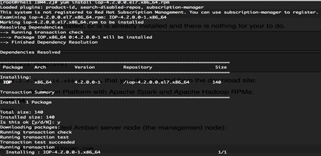
4. From a host connected to the internet, download the required IBM repository files and transfer to the admin node:
#mkdir -p /tmp/IBM
#cd /tmp/IBM/
5. To download the Ambari repo go to:
#wget http://ibm-open-platform.ibm.com/repos/Ambari/rhel/7/x86_64/2.2.x/GA/2.2.0/ambari-2.2.0.el7.x86_64.tar.gz
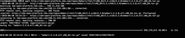
6. Download the IOP repo at:
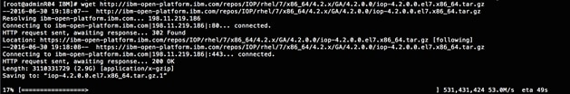
7. Download the IOP-UTILS repo at:
#wget http://ibm-open-platform.ibm.com/repos/IOP-UTILS/rhel/7/x86_64/1.2/iop-utils-1.2.0.0.el7.x86_64.tar.gz
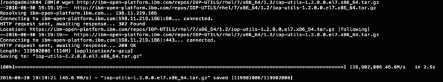
8. Copy the repository directory to the admin node:
#scp -r /tmp/IBM/ rhel1:/var/www/html /repos
9. Extract the files login to rhel1:
#cd /var/www/html/repos
#tar –zxvf ambari-2.2.0.el7.x86_64.tar.gz
#tar –zxvf iop-4.2.0.0.el7.x86_64.tar.gz
#tar –zxvf iop-utils-1.2.0.0.el7.x86_64.tar.gz
10. Update the ambari.repo file to use the local repository set up above.
#vi /etc/yum.repos.d/ambari.repo
[BI_AMBARI-2.2.0]
name=ambari-2.2.0
baseurl=http://10.4.1.31/repos/Ambari/RHEL7/x86_64/2.2.0/
enabled=1
gpgcheck=0
11. Update the baseurl with the webserver’s address where the local repo is available as shown above.
12. Clean the yum cache on all nodes so that the right packages from the remote repository are seen by the local yum.
# clush –a –b yum clean all

13. Install the Ambari server on the admin management node, using the following command:
#yum install ambari-server
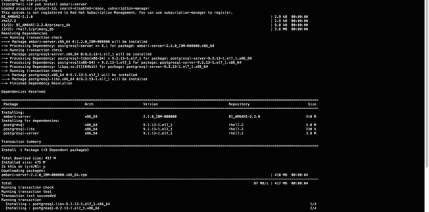
14. Update the value for the baseurl in the file below:
/var/lib/ambari-server/resources/stacks/BigInsights/4.2/repos/repoinfo.xml
with the urls for the local repository as shown below:
#vi /var/lib/ambari-server/resources/stacks/BigInsights/4.2/repos/repoinfo.xml
<reposinfo>
<mainrepoid>IOP-4.2</mainrepoid>
<os family="redhat7">
<repo>
<baseurl>http://10.4.1.31/repos/IOP/RHEL7/x86_64/4.2.0.0/</baseurl>
<repoid>IOP-4.2</repoid>
<reponame>IOP</reponame>
</repo>
<repo>
<baseurl>http://10.4.1.31/repos/IOP-UTILS/rhel/7/x86_64/1.2/</baseurl>
<repoid>IOP-UTILS-1.2</repoid>
<reponame>IOP-UTILS</reponame>
</repo>
</os>
</reposinfo>
15. Edit the file /etc/ambari-server/conf/ambari.properties to update the JDK location from the IOP-UTILS repository as shown below:
#vi /etc/ambari-server/conf/ambari.properties
openjdk1.8.url=http://10.4.1.31/repos/IOP-UTILS/rhel/7/x86_64/1.2/openjdk/jdk-1.8.0.tar.gz
Set Up the Ambari server
1. Run the following command and accept the default settings:
#ambari-server setup
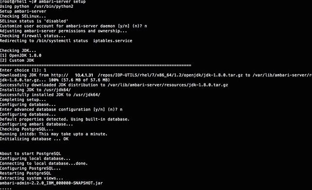
2. Start the Ambari server, using the following command:
#ambari-server start
3. Ensure that the postgresql service, which is used by Ambari, starts automatically on reboot.
4. Run the following command on the admin node:
#systemctl start postgresql.service
#systemctl enable postgresql.service
Ambari Server Components Set up
1. Once the Ambari service has been started, access the Ambari Install Wizard through the browser.
2. Point the browser to http:// 10.4.1.31:8080.
3. Log in to the Ambari Server using the default username/password: admin/admin. This can be changed at a later period of time. (Figure 80)
Once logged in, the “Welcome to Apache Ambari” window appears. (Figure 81)
Figure 81 Apache Welcome Window
Creating a Cluster
To create a cluster, complete the following steps.
1. Click the Launch Install Wizard button.
2. On the Get started page type “Cisco_BI42” as the name for the cluster in the text box. Click the Next button. (Figure 82)
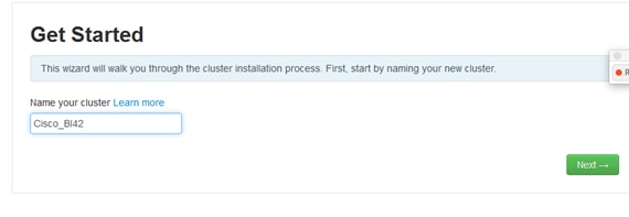
Select a Stack
1. On the following screen, select the BigInsights 4.2 stack. (Figure 83)
2. Expand “Advanced Repository Options” to check that it is pointed to the local repository on the admin node.
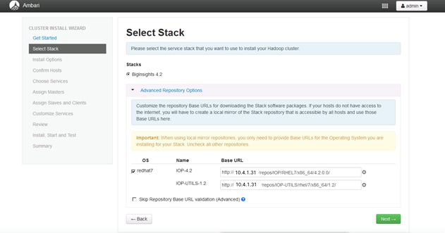
IOP Installation
In order to build up the cluster, the install wizard needs to know general information about how the cluster has to be set up. This requires providing the Fully Qualified Domain Name (FQDN) of each of the hosts. The wizard also needs to access the private key file that was created in Set Up Password-less SSH. It uses these to locate all the hosts in the system and to access and interact with them securely.
1. Use the Target Hosts text box to enter the list of host names, one per line. Ranges inside brackets can be used to indicate larger sets of hosts. (Figure 84)
2. Select the option Provide your SSH Private Key in the Ambari cluster install wizard.
3. Copy the contents of the file /root/.ssh/id_rsa on rhel1 and paste it in the text area provided by the Ambari cluster install wizard.
Figure 84 Ambari Install Options
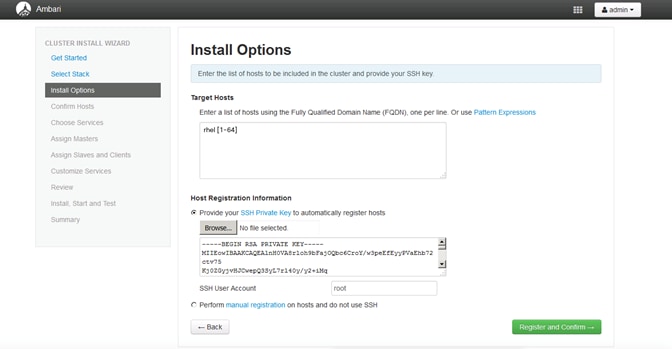
4. Click on register and confirm to continue with the installation.
Confirm Hosts
This screen ensures that Ambari has located the correct hosts for the cluster and checks those hosts to make sure they have the correct directories, packages, and processes to continue the install. (Figure 85)
If any host was selected in error, it can be removed by selecting the appropriate checkboxes and clicking the grey Remove Selected button.
1. To remove a single host, click the small white Remove button in the Action column. When the lists of hosts are confirmed, click Next.
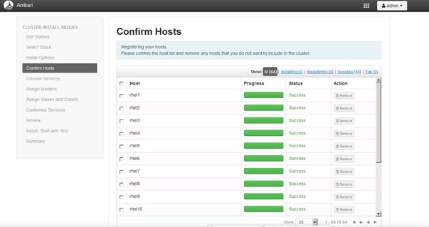
Host checks ( all hosts are in order).
Choose Services
IOP is made up of a number of components.
1. Select All to preselect all items. (Figure 86)
2. When done, click Next.
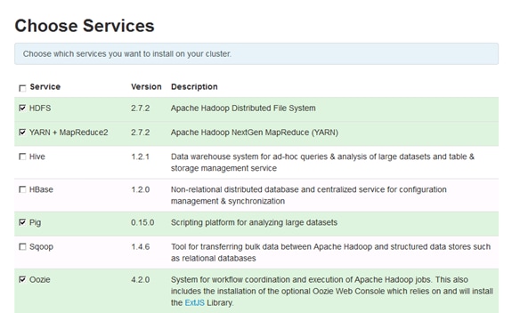
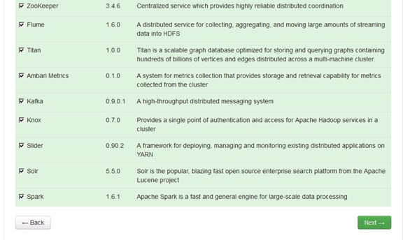
Assign Masters
The Ambari install wizard attempts to assign the master nodes for various services that have been selected to appropriate hosts in the cluster. The right column shows the current service assignments by host, with the hostname and its number of CPU cores and amount of RAM indicated. (Figure 87)
1. Reconfigure the service assignments to match the values in Table 6 below.
| Service Name |
Host |
| NameNode |
rhel1 |
| SNameNode |
rhel2 |
| HistoryServer |
rhel1 |
| App Timeline Server |
rhel2 |
| ResouceManager |
rhel2 |
| Hive Metastore |
rhel1 |
| WebHCat Server |
rhel1 |
| HiveServer2 |
rhel1 |
| HBase Master |
rhel2 |
| Oozie Server |
rhel1 |
| Zookeeper |
rhel1, rhel2, rhel3 |
| Spark History Server |
rhel1 |
| Kafka Broker |
rhel3 |
| Knox Gateway |
rhel1 |
| Metrics Collector |
rhel1 |
There is one broker by default, add more based on requirements.
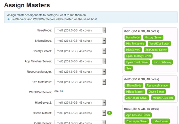
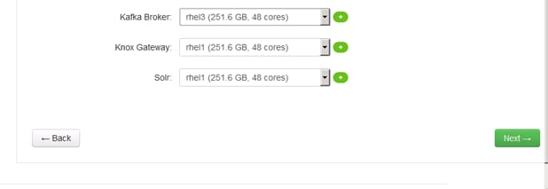
1. Click the Next button.
Assign Slaves and Clients
The Ambari install wizard attempts to assign the slave components (DataNodes, NFSGateway, NodeManager, RegionServers, Flume, Spark Thrift Server and Client) to appropriate hosts in the cluster. Reconfigure the service assignment to match the example shown in Figure 88 and Table 7 below:
1. Assign DataNode, NodeManager, RegionServer, and Flume on nodes rhel3- rhel64.
2. Assign Client to all nodes.
3. Click the Next button.
Table 7 Assign Client Services and Hosts
| Client Service Name |
Host |
| DataNode |
rhel3-rhel64 |
| NFSGateway |
rhel1 |
| NodeManager |
rhel3-rhel64 |
| RegionServer |
rhel3-rhel64 |
| Flume |
rhel3-rhel64 |
| Spark Thrift Server |
rhel1 |
| Client |
All nodes, rhel1-rhel64 |
Figure 88 Assign Slaves and Clients
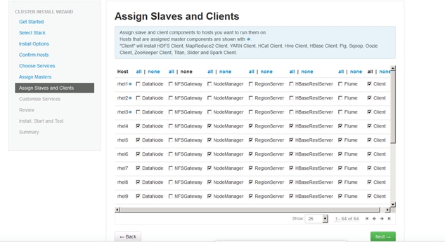
Customize Services
This section describes the tabs that manage configuration settings for Hadoop components. The wizard attempts to set reasonable defaults for each of the options here, but this can be modified to meet specific requirements. The following sections provide configuration guidance that should be refined to meet specific use case requirements, memory and service level settings for each component and service level tuning.
HDFS
In Ambari, choose the HDFS Service tab and use the “Search” box on top to filter for the properties mentioned in the table to update their values to those shown in Table 8 .
HDFS JVM Settings
1. Update the following HDFS configurations in Ambari:
| Property Name |
Value |
| NameNode Java Heap Size |
4096 |
| Hadoop maximum Java heap size |
4096 |
| DataNode maximum Java heap size |
4096 |
| DataNode Volumes Failure Toleration |
3 |
MapReduce2
1. In Ambari, choose MapReduce Service from the tab and use the “Search” box on top to filter for the properties mentioned in Table 9 to update their values.
2. Update the following MapReduce 2 configurations:
| Property Name |
Value |
| Default virtual memory for a job's map-task |
4096 |
| Default virtual memory for a job's reduce-task |
8192 |
| Sort allocation memory (mapreduce.task.sort.io.mb) |
1638 |
| yarn.app.mapreduce.am.resource.mb |
4096 |
| mapreduce.map.java.opts |
-Xmx3276m |
| mapreduce.reduce.java.opts |
-Xmx6552m |
| yarn.app.mapreduce.am.command-opts |
-Xmx6552m |
YARN
1. In Ambari, choose the YARN Service from the tab and use the “Search” box on top to filter for the properties mentioned in Table 10 below to update their values.
2. Update the following YARN configurations:
Table 10 YARN Configuration Values
| Property Name |
Value |
| ResourceManager Java heap size |
4096 |
| NodeManager Java heap size |
2048 |
| yarn.nodemanager.resource.memory-mb |
184320 |
| YARN Java heap size |
4096 |
| yarn.scheduler.minimum-allocation-mb |
4096 |
| yarn.scheduler.maximum-allocation-mb |
184320 |
Hive
Choose Hive Service from the tab (Figure 89) and select the Advanced tab and make the changes below:
1. Select New MySQL Database
a. Database Name: hive
b. Database Username: hive
2. Enter the Hive database password as per organizational policy.
Figure 89 Customize Hive Services
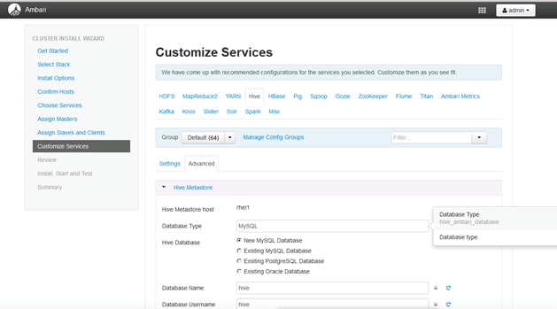
HBase
In Ambari, choose HBASE Service from the tab and use the “Search” box on top to filter for the properties mentioned in Table 11 to update their values.
1. Update the following HBASE configurations:
| Property Name |
Value |
| HBase Master Maximum Java Heap Size |
4096 |
| HBase RegionServers Maximum Java Heap Size |
16384 |
![]() Note: If HBase is not running, keep the default value of 1024 for the Java Heap size for HBase RegionServers and HBase Master.
Note: If HBase is not running, keep the default value of 1024 for the Java Heap size for HBase RegionServers and HBase Master.
Oozie
Similarly, under the Oozie tab (Figure 90), change the default log location by finding the Log Dir property and modifying the /var prefix to /data/disk1.
1. Select New Derby Database
2. Name the database oozie
3. Name the username oozie
Figure 90 Customize Oozie Services
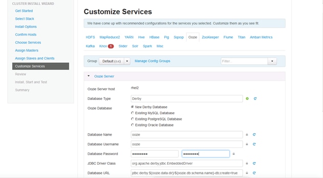
Knox
Choose Knox Service from the tab (Figure 91) and expand the Knox gateway tab and make the changes below:
1. Enter the Knox Master Secret password as per organizational policy.
Figure 91 Customize Knox Services
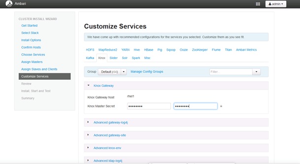
Review
The assignments that have been made are displayed. Check to ensure everything is correct before clicking on Deploy button. If any changes are to be made, use the left navigation bar to return to the appropriate screen. (Figure 92)
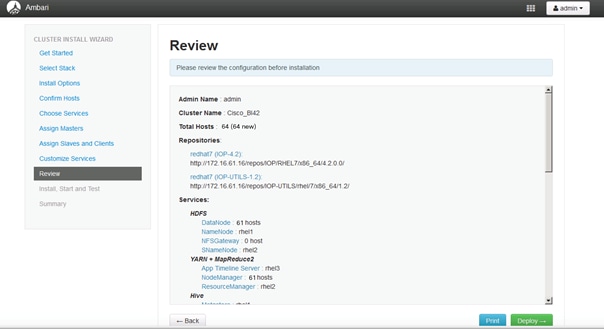
The progress of the install is shown on the screen. Each component is installed and started and a simple test is run on the component. The next screen displays the overall status of the install in the progress bar at the top of the screen and a host-by-host status in the main section.
1. To see specific information on what tasks have been completed per host, click the link in the Message column for the appropriate host.
2. In the Tasks pop-up, click the individual task to see the related log files.
3. Select filter conditions by using the Show dropdown list.
4. To see a larger version of the log contents, click the Open icon. To copy the contents to the clipboard, use the Copy icon.
Depending on which components are installing, the entire process may take 10 or more minutes. (Figure 93)
5. When successfully installed and started, the service appears, click Next.
Summary of Install Process
The Summary page shows a summary of the accomplished tasks. Click Complete.
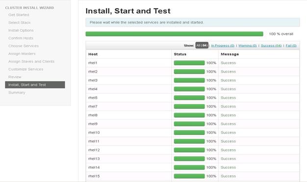
The Summary page shows a summary of the accomplished tasks. (Figure 94)
1. Click Complete to finish the installation.
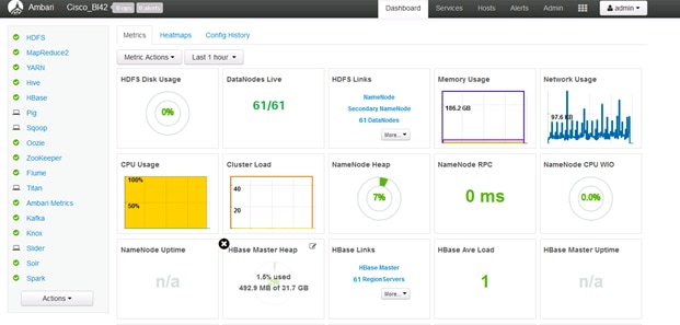
Enabling High Availability
The idea behind providing High Availability is to ensure the availability of all critical services:
· Without any SLA violations
· Planned or scheduled outages
· Mask unplanned outages (crashes, etc.).
HDFS High Availability
The HDFS HA feature provides the option of running two NameNodes in the same cluster. These NameNodes are referred to as: the Active and the Standby. The Standby NameNode, allowing a fast failover to a new NameNode during a graceful administrator-initiated failover for the purpose of planned maintenance or in the event of machine crashes (unplanned outage).
To setup NameNode high availability, complete the following steps:
1. From the Ambari dashboard, click HDFS Service (Figure 95).
2. Select Service Actions > Enable NameNode HA.
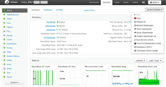
The Enable NameNode HA wizard (0) opens the Enable HA NameNode Wizard. (Figure 96)
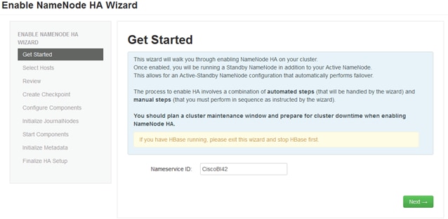
3. On the Select Hosts page, select which hosts to use for additional NameNodes and JournalNodes. (Figure 97)
Figure 97 Select Hosts For NameNode
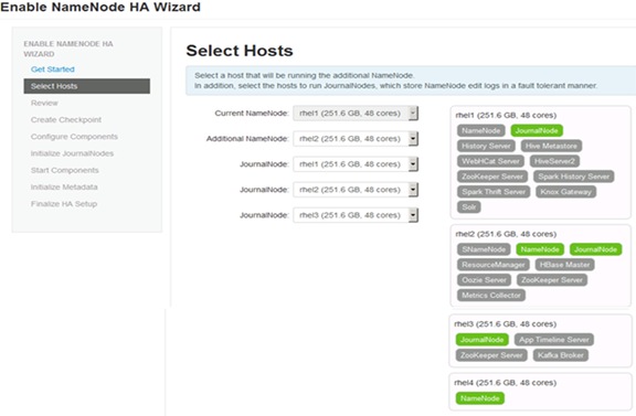
4. On the Review page (Figure 98), confirm the selections. To change any values, click Back, to continue, click Next.
Figure 98 Review Host Selections
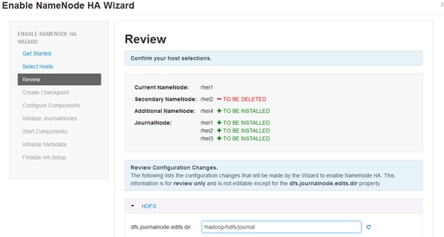
5. Create a checkpoint on the NameNode with some manual steps on the Linux server (rhel1). (Figure 99)
Figure 99 Create a Check Point on the NameNode
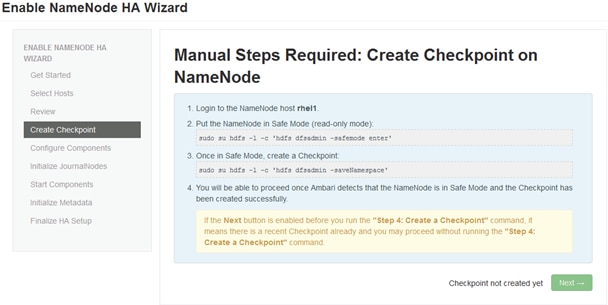
6. Log in to the current NameNode host.
7. Run the following command to put the NameNode into safe mode.

8. Create the checkpoint.
9. Return to the Ambari web interface. When Ambari detects success, click Next. (Figure 100)
Figure 100 Create a Check Point on the NameNode
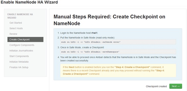
10. See the progress bars on the Configure Components page, as the wizard configures the components. When all the configuration steps are complete, click Next. (Figure 101)
Figure 101 Configure Components
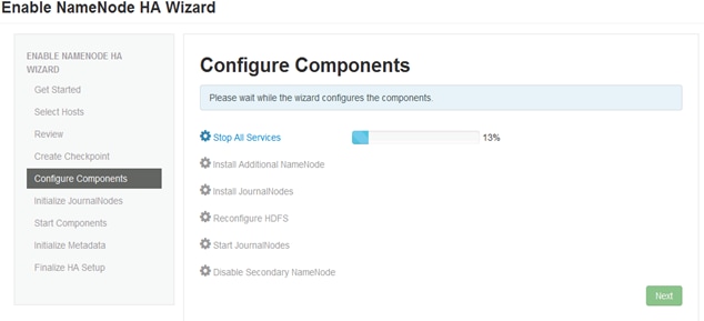
11. Initialize the JournalNodes with the manual step below (Figure 102):
12. Log in to the current NameNode host.
13. Run the following command to initialize the JournalNodes:
sudo su hdfs –l -c "hdfs namenode –initializeSharedEdits"
Figure 102 Initialize JournalNodes
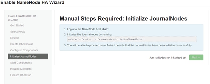
14. Return to the Ambari web interface. When Ambari detects success, click Next. (Figure 103)
Figure 103 JournalNodes Initialized
15. On the start Components page (Figure 104), the wizard starts the Zookeeper servers and the NameNode. Once done, click Next.
Figure 104 Start Components
To initialize NameNode HA Metadata, complete the following steps at the NameNode host (rhel1) (Figure 105):
1. Initialize the metadata for NameNode (automatic failover):
sudo su hdfs -l -c 'hdfs zkfc -formatZK'
2. Login to the additional NameNode host (rhel4):
3. Run the following command to initialize the metadata for the additional NameNode:
sudo su -l hdfs -c 'hdfs namenode -bootstrapStandby'
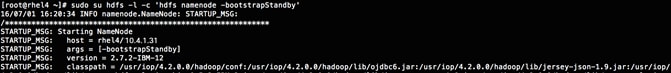
4. Return to the Ambari web Interface. Click Next, when Ambari detects success.
Figure 105 Initialize NameNode HA
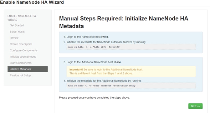
On the Finalize HA setup page (Figure 106), the user can see the progress bars as the wizard completes the High Availability setup.
5. When complete click Done.
Figure 106 Final HA Set Up
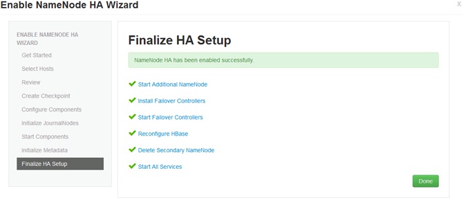
6. Once the setup is complete, the Ambari web interface will reload. Please confirm to see if any services need to be restarted. (Figure 106)
Figure 107 Ambari Summary
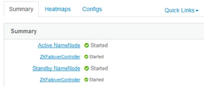
Setting Up Resource Manager (Yarn) High Availability
The process of setting up High Availability for Yarn, sets up a standby resource manager so that if active resource manager goes down, standby takes over and Yarn can continue to function.
![]() Note: At least three Zookeeper servers must be running.
Note: At least three Zookeeper servers must be running.
1. From the Ambari web interface, click on the Yarn service (Figure 108).
Figure 108 YARN
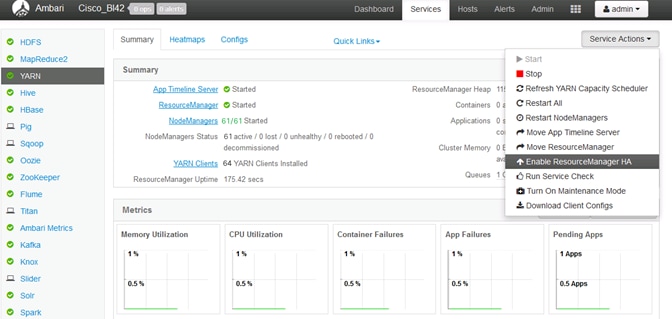
This will open the Resource Manager HA setup wizard (Figure 109):
Figure 109 HA Wizard
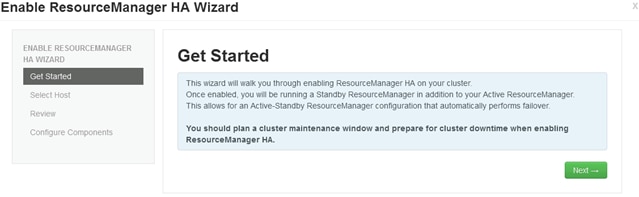
2. From the Select Hosts page, choose the host for Additional Resource Manager (Figure 110).
Figure 110 Select Host for ResourceManager
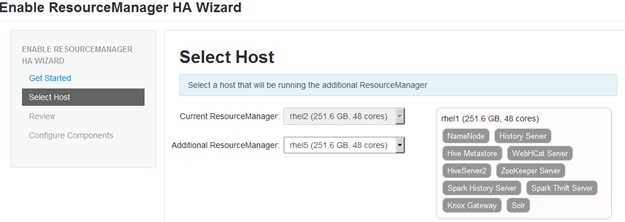

3. Proceed to the Review screen (Figure 111).
Figure 111 HA Wizard
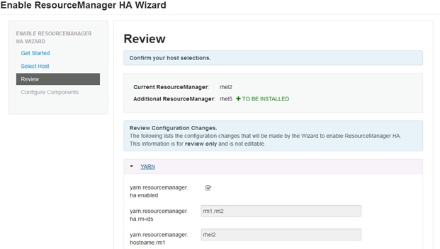
The Configure Components screen (Figure 112) shows the progress bars as the Additional Resource Manager is being deployed.
Figure 112 Configure Components
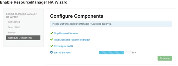
Once complete, the Ambari web interface reloads and informs the user to restart the required services.
The active and standby ResourceManagers show they are successfully restarted.
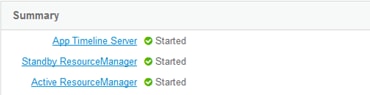
![]() Below are the steps for installing BigSQL. This was done separately so the user may notice a difference in the number of nodes, but all the above steps still apply.
Below are the steps for installing BigSQL. This was done separately so the user may notice a difference in the number of nodes, but all the above steps still apply.
BigSQL Installation
How to Acquire BigInsights Value-add Services
For complete download information (including part numbers and SKUs), please go to:
http://www-01.ibm.com/support/docview.wss?uid=swg24042361
In the context of this document, the user will obtain “biginsights_4.2.0.0.el7.x86_64.bin” from the Passport Advantage portal. This file is used to deploy BigInsights 4.2 over Redhat Enterprise Linux 7.
When the user runs the bin file, they will be prompted with the option to download the RPM packages. Then the user may proceed to download the RPMs tar-ball.
Prechecks and Preconditions
It is important to take care of the following precheck criteria before starting with the BigSQL installation on the cluster. To take care of the prechecks and preconditions, complete the following steps:
1. Install KornShell (KSH):
![]() Note: It is important that KSH be installed on all the nodes.
Note: It is important that KSH be installed on all the nodes.
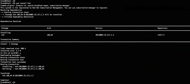
2. Disable requiretty: open the file /etc/sudoers and comment out the line “default requiretty”
visudo –f /etc/sudoers


The changes shown above need to be made on all the nodes that will be part of the BigSQL installation.
3. The storage subsystem should have disks of sector size 512 Bytes.
![]() Important Caveat/Note: The storage disks on the nodes being used for the BigSQL installation should have the sector size of 512 bytes. Otherwise, the user will receive the error "SQLCODE-902".
Important Caveat/Note: The storage disks on the nodes being used for the BigSQL installation should have the sector size of 512 bytes. Otherwise, the user will receive the error "SQLCODE-902".
4. All the server nodes should have Fully Qualified Domain Names, example, rhel1.cisco.com.
To install BigSQL complete the following steps:
1. Untar the downloaded BigInsights 4.2 package. All the server nodes should have
After untar the package: “BigInsights-Valuepacks” appears.

2. Create the folder:
/var/www/html/repos/valueadds
3. Copy the downloaded RPMs to this folder.
# cp /root/BigInsights-Valuepacks/RHEL7/x86_64/4.2.0.0/* /var/www/html/repos/valueadds/
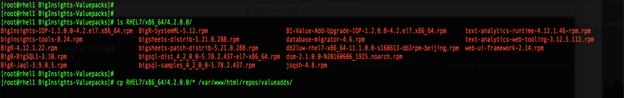
4. Run createrepo in the /var/www/html/repos/valueadds folder.

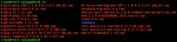
5. Run “yum install BigInsights-IOP-1.2.0.0-4.2.el7.x86_64.rpm”
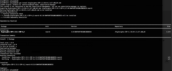
6. Check for BIGINSIGHTS-VALUEPACK-1.2.0.0.repo under /etc/yum.repos.d
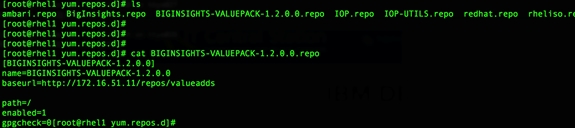
7. Update /var/lib/ambari-server/resources/stacks/BigInsights/4.2/repos/repoinfo.xml file to include:
<repo>
<baseurl>http://172.16.51.11/repos/valueadds</baseurl><repoid>BIGINSIGHTS-VALUEPACK-1.2.0.0</repoid>
<reponame>BIGINSIGHTS-VALUEPACK-1.2.0.0</reponame>
</repo>
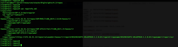
8. Restart the Ambari server, to reflect the new services to be installed.
9. Issue the command:
service ambari-server restart.
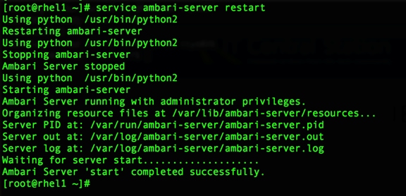
Once the Ambari server has restarted, the user can see the new services on the web interface.
10. Login to the Ambari server again.
11. Proceed to install the BigSQL service.
12. From the Actions tab, choose “Add Service”.
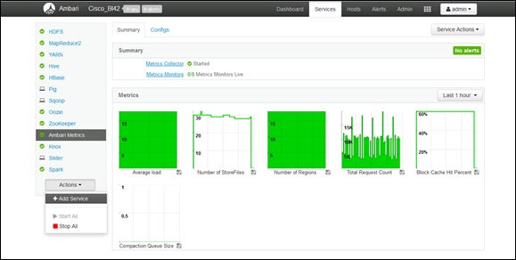
13. From the “Add Service Wizard”, choose “BigInsights BigSQL” service and click Next.

14. Choose the node on which to install the BigSQL head. (rhel1.cisco.com in this installation example.)
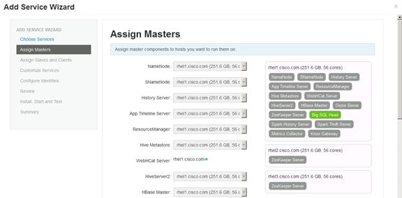
15. Click Next.
16. Proceed to choose nodes to assign BigSQL worker nodes.
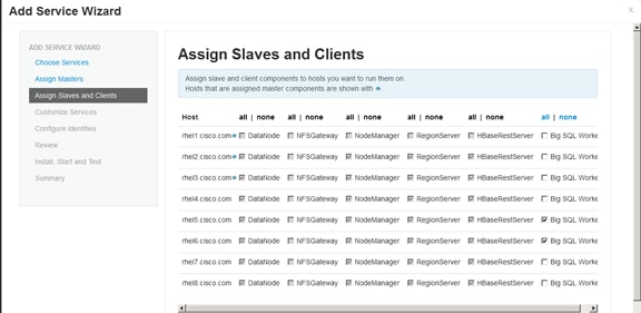
(rhel5.cisco.com and rhel6.cisco.com in this example).
17. After selecting the worker nodes, click Next.
The user will be prompted to customize the service and set up the environment. Any issues and open items will be pointed out now.
For e.g. Bigsql_user_password is missing here and the user will be prompted to enter the password.
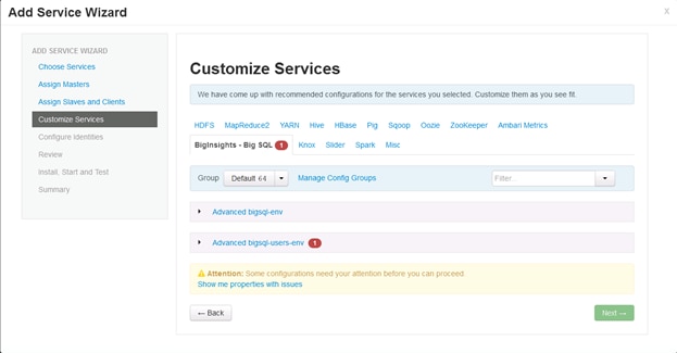
18. Once the password is set, click Next.
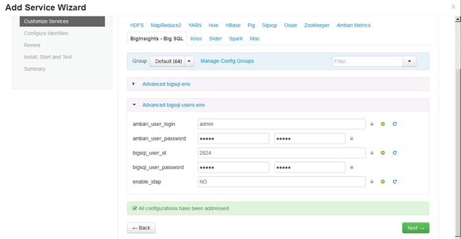
If prompted to make configuration changes based on Ambari recommendations, make the appropriate changes or click “proceed anyway”.
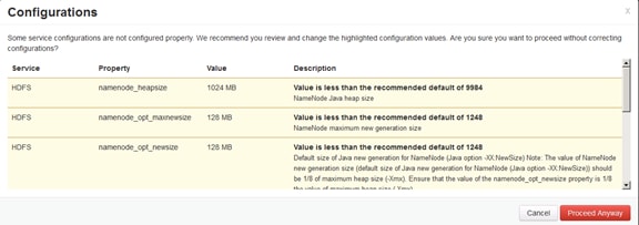
19. Confirm the head node and worker nodes.
20. Click “Deploy” on the review screen.
21. Click “Deploy” to start the install process.
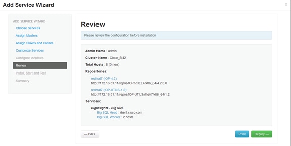
22. Click “Deploy” to start the install process.
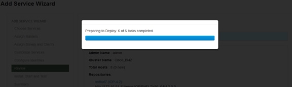
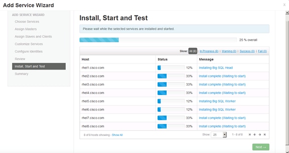
Install progress:
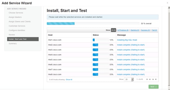
The user can also check and track progress through the log file under /tmp/bigsql/logs/:
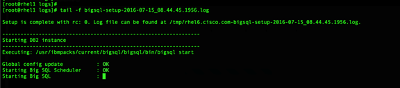
Once complete, the installation will show success as:
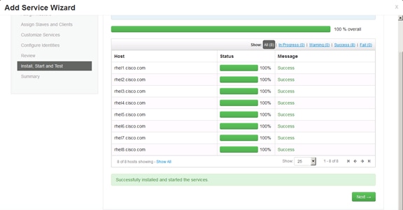
After the successful installation, the user will be prompted for the warning to restart other services for the BigSQL service to work properly.
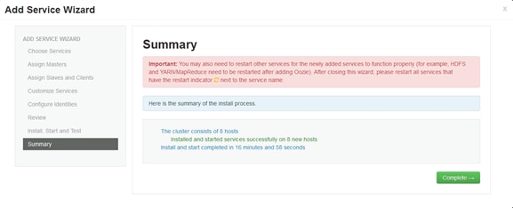
23. Click “Complete” to go back to the Ambari screen with the BigSQL service successfully installed and some services requiring a restart.
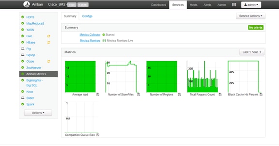
24. Restart all services Hive, Hbase etc.
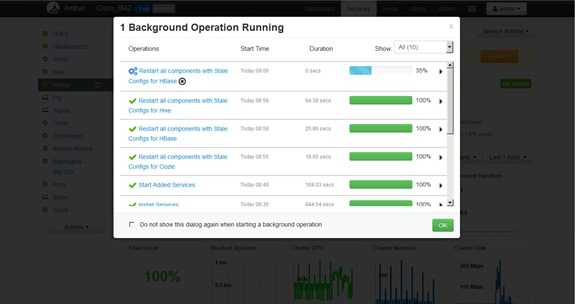
Once all services are restarted, the Ambari Service will display the installation details:
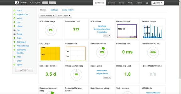
This section provides the BOM for the 64 nodes Performance Optimized Cluster. See Table 12 for BOM for the master rack, Table 13 for BOM for expansion racks (racks 2 to 4), Table 14 for software components.
![]() If UCSD-SL-CPA4-P2 is added to the BOM all the required components for 16 servers only are automatically added. If not customers can pick each of the individual components that are specified after this and build the BOM manually.
If UCSD-SL-CPA4-P2 is added to the BOM all the required components for 16 servers only are automatically added. If not customers can pick each of the individual components that are specified after this and build the BOM manually.
Table 12 Bill of Materials for C240M4SX Base Rack
Table 13 Bill of Materials for Expansion Racks
Table 14 Red Hat Enterprise Linux License
| Red Hat Enterprise Linux |
||
| RHEL-2S2V-3A |
Red Hat Enterprise Linux |
64 |
| CON-ISV1-EL2S2V3A |
3 year Support for Red Hat Enterprise Linux |
64 |
Rajesh Shroff, Big Data Solutions Architect, Data Center Solutions Group, Cisco Systems, Inc.
Rajesh is a big data infrastructure and performance engineer, with focus on solutions and emerging trends in big data and analytics.
Acknowledgements
· Chinmayi Narasimhadevara, Big Data Software Engineer, Data Center Solutions Group, Cisco Systems, Inc.
· Mike Ahern, Big Data Performance, IBM
· Kathy A. McKnight, Senior Technical Staff Member, Big SQL and DB2 Development, IBM
· Barbara Dixon, Technical Writer, Data Center Solutions Group, Cisco Systems, Inc.
· Karthik Karupasamy, Big Data TME, Data Center Solutions Group, Cisco Systems Inc.
Setting Up Network Bonding
Network bonding can be setup on the vNICs on the hosts for redundancy as well as for increased throughput.
VLANs are configured as shown in Table 15 below:
| VLAN |
Fabric |
NIC Port |
Function |
| Vlan19 |
|
bond0 |
Data |
|
|
A |
eth0 |
Data |
|
|
B |
eth1 |
Data |
|
|
A |
eth2 |
Data |
|
|
B |
eth3 |
Data |
|
|
A |
eth4 |
Data |
|
|
B |
eth5 |
Data |
All NICs are carrying data traffic in Vlan19.
Figure 113 Set up Network Bonding
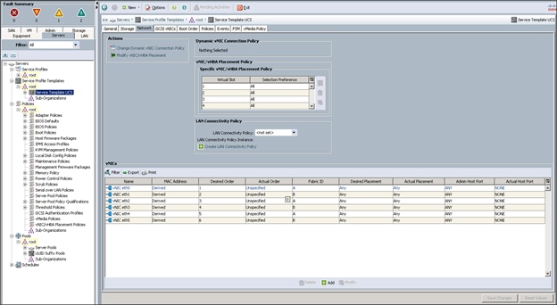
16 upstream ports bundled in Port channel created between Fabric Interconnect and upstream switch (Nexus N9K-C9372PX)
1. Configure eth0 as shown below in Figure 114 and click on Apply to enable the changes.
Figure 114 Configure eth0
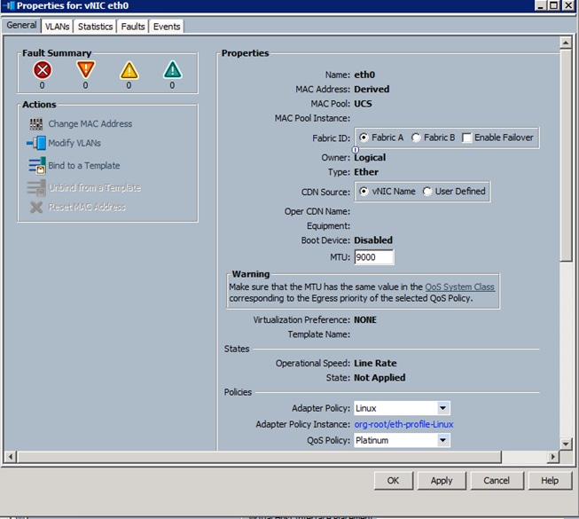
All vNICs (eth0-eth5) are the same with the above configuration.
· eth0, eth2 and eth4 are on the link going to Fabric A
· eth1, eth3 and eth5 are on the link going to Fabric B
· All 6 vNICs are bonded together in Mode 6 to form bond0 interface.
![]() Note: The following steps need to done on the Host machines for configuring bonding on the OS.
Note: The following steps need to done on the Host machines for configuring bonding on the OS.
2. Use bonding mode 6 for Bonding Options on the Host O.S. in the ifcfg-eth* file
BONDING_OPTS="mode=6 miimon=100 xmit_hash_policy=0"
Sample ifcfg-eth0 file
DEVICE="eth0"
BOOTPROTO="none"
MTU="9000"
ONBOOT="yes"
TYPE="Ethernet"
MASTER=bond0
SLAVE=yes
3. All the vNICs that are being bonded will need to be configured as SLAVES on all the hosts as shown above, and with bond0 as the master shown below.
Sample ifcfg-bond0 file
DEVICE=bond0
TYPE=Bond
BONDING_MASTER=yes
DEFROUTE=yes
IPV4_FAILURE_FATAL=no
NETMASK=255.255.255.0
GATEWAY=$GATEWAYIP
BONDING_OPTS="mode=6 miimon=100 xmit_hash_policy=0"
BOOTPROTO="none"
ONBOOT="yes"
MTU="9000"
IPADDR=”$HOSTIP”
 Feedback