- What's In This Guide
- Using the Cisco TelePresence System Administration Interface
- Understanding the Fields In the Cisco TelePresence System Administration Interface
- Device Information
- Configuring the Cisco TelePresence System
- Monitoring the Cisco TelePresence System
- Satellite Licenses for the Cisco TelePresence System
- Glossary
- Index
Administration Guide for Cisco TelePresence Software Release 1.10
Bias-Free Language
The documentation set for this product strives to use bias-free language. For the purposes of this documentation set, bias-free is defined as language that does not imply discrimination based on age, disability, gender, racial identity, ethnic identity, sexual orientation, socioeconomic status, and intersectionality. Exceptions may be present in the documentation due to language that is hardcoded in the user interfaces of the product software, language used based on RFP documentation, or language that is used by a referenced third-party product. Learn more about how Cisco is using Inclusive Language.
- Updated:
- April 3, 2013
Chapter: Understanding the Fields In the Cisco TelePresence System Administration Interface
Understanding the Fields In the Cisco TelePresence System Administration Interface
Contents
This chapter contains the following sections:
•![]() Fields in the Troubleshooting Area
Fields in the Troubleshooting Area
Fields in the Configuration Area
This section contains information about the fields that are in the Configuration area and contains the following topics:
IP Settings
The IP Settings window displays the CTS MAC address and hostname and you can view and manage the following:
•![]() DHCP—Choose Yes if your network uses the Dynamic Host Configuration Protocol (DHCP) to dynamically assign a network address for your system. Choose No to assign a static address for your system if your network does not use DHCP.
DHCP—Choose Yes if your network uses the Dynamic Host Configuration Protocol (DHCP) to dynamically assign a network address for your system. Choose No to assign a static address for your system if your network does not use DHCP.
•![]() Domain name
Domain name
•![]() IP Address
IP Address
•![]() Default gateway
Default gateway
•![]() DNS servers.
DNS servers.
For more information about this field, see the "IP Settings" section.
Network Settings
You can view or configure the following settings in the Network Settings window:
•![]() Operational VLAN ID
Operational VLAN ID
•![]() Administrative VLAN ID
Administrative VLAN ID
•![]() Syslog Address
Syslog Address
For more information about this field, see the "Network Settings" section.
Unified CM Settings
This field allows you to view and configure TFTP server locations and view a list of available settings for this Cisco TelePresence system. For more information about this field, see the "Cisco Unified Communications Manager Settings" section.
Address Book
The Address Book window displays read-only entries that have been set in Unified CM. You can create favorites for up to 40 meeting rooms.
To view the phone list of Cisco TelePresence system-enabled meeting rooms, follow these steps:
Step 1 ![]() Choose Configuration > Address Book.
Choose Configuration > Address Book.
Step 2 ![]() Use Unified CM to make changes to the Address Book. To add entries to the address book, refer to the "Managing the Speed-Dial Directory (Favorites)" section of the See the Cisco Unified Communications Manager Configuration Guide for the Cisco TelePresence System.
Use Unified CM to make changes to the Address Book. To add entries to the address book, refer to the "Managing the Speed-Dial Directory (Favorites)" section of the See the Cisco Unified Communications Manager Configuration Guide for the Cisco TelePresence System.
Telephony Settings
The Telephony Settings window displays read-only information about the telephony settings for the Cisco TelePresence System that were set in Unified CM. For more information about this field, see the "Telephony Settings" section.
SNMP Settings
Use this field to view a report of the SNMP configuration. For more information about this field, see the "SNMP Settings" section.
System Settings
This field allows you to view Unified CM configuration settings for your system. For more information about this field, see the "SNMP Settings" section.
Security Settings
Use this field to view or download the MIC or LSC certificates that are used for your system. For more information about this field, see the "Security Settings" section.
Fields in the Troubleshooting Area
This section describes the fields that are available in the Troubleshooting area and contains the following topics:
Hardware Setup
Cisco TelePresence System Administration includes a diagnostics interface for the Cisco TelePresence System EX Series (CTX).
To access all available troubleshooting tasks, go to Troubleshooting > Hardware Setup.
If your GUI has tabs visible in this window, select one of the following tabs:
•![]() Device Test: You can use the following Cisco TelePresence system troubleshooting features:
Device Test: You can use the following Cisco TelePresence system troubleshooting features:
•![]() CTX Tests (Not Available on All Systems): Test reverberation and noise levels for some systems (not available for all systems).
CTX Tests (Not Available on All Systems): Test reverberation and noise levels for some systems (not available for all systems).

Note ![]() Not every system has the CTX test available; in this case, the tab is not visible.
Not every system has the CTX test available; in this case, the tab is not visible.
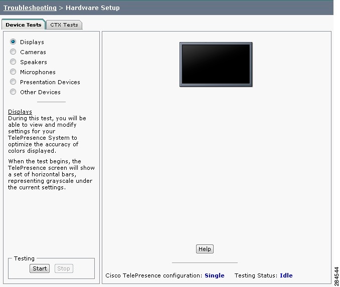
Device Test
The Device Tests tab provides the traditional Hardware Setup troubleshooting tasks for the following Cisco TelePresence System peripherals:
•![]() Devices
Devices
•![]() Cameras
Cameras
•![]() Speakers
Speakers
•![]() Microphones
Microphones
•![]() Presentation Devices
Presentation Devices
•![]() Other Devices
Other Devices
Figure 2-1 shows the CTS device troubleshooting window.
Figure 2-1 CTS Device Troubleshooting Window
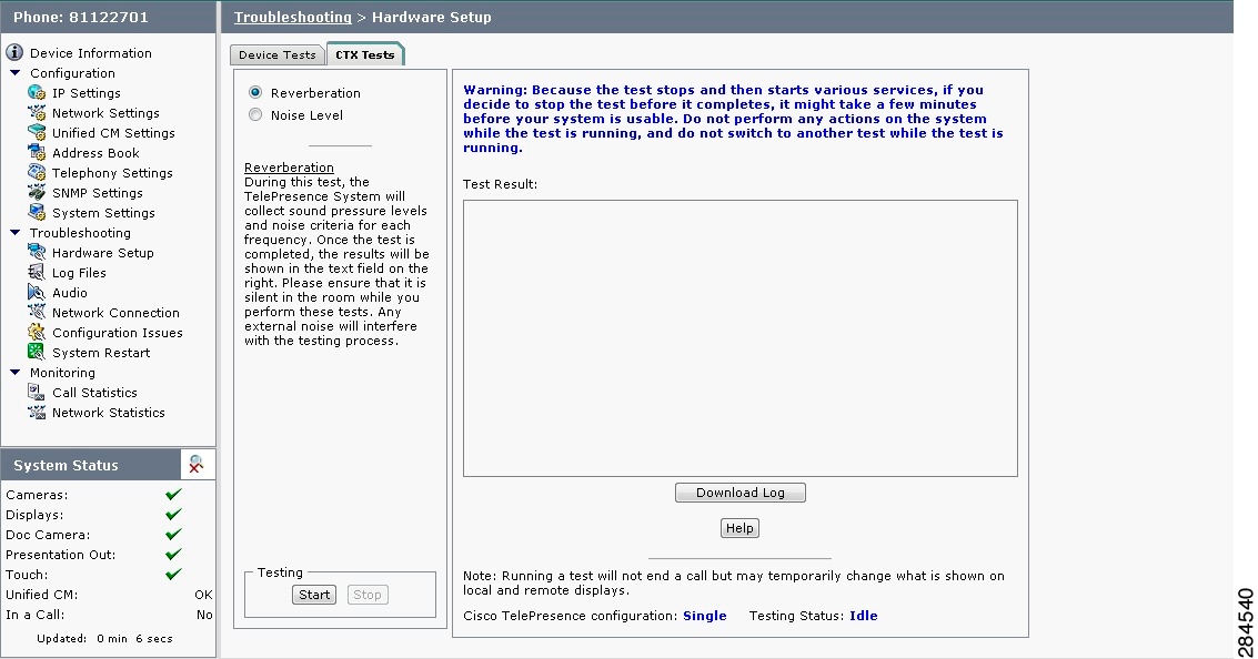
CTX Tests (Not Available on All Systems)
The CTX Tests tab provides the following troubleshooting tasks for the CTX:
Note ![]() Running a test will not end a call but may temporarily change what is shown on local and remote displays.
Running a test will not end a call but may temporarily change what is shown on local and remote displays.
Because the test stops and then starts various services, if you decide to stop the test before it completes, it might take a few minutes before your system is usable. Do not perform any actions on the system while the test is running, and do not switch to another test while the test is running.
Figure 2-2 shows the CTX Tests window.
Figure 2-2 CTX Tests
Reverberation
During this test, the Cisco TelePresence System collects sound pressure levels and noise criteria for each frequency. Once the test is completed, the results are shown in the Test Results.

Tip ![]() Ensure that the room is silent while you perform these tests. Any external noise will interfere with the testing process.
Ensure that the room is silent while you perform these tests. Any external noise will interfere with the testing process.
Step 1 ![]() Select the Reverberation radio button and then click Start.
Select the Reverberation radio button and then click Start.
The system issues the following information:
"Test Running: Test is running. Please wait until the test completes; if you stop the test, no results will be recorded."
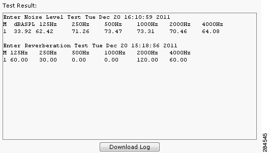
The test takes a few minutes to complete. When complete, system reverberation information is displayed in the Test Results window, as shown in Figure 2-3.
Figure 2-3 Reverberation Test Results

Step 2 ![]() If desired, click Download Log.
If desired, click Download Log.
The system asks whether you want to open or save the .txt file. This completes the reverberation test.
Noise Level
During this test, the Cisco TelePresence System plays audio chirps and collects the average sound decays for each frequency. Once the test is completed, the results are shown in the text field.
Tip ![]() Ensure that the room is silent while you perform these tests. Any external noise will interfere with the testing process.
Ensure that the room is silent while you perform these tests. Any external noise will interfere with the testing process.
Step 1 ![]() Select the Noise Level radio button and then click Start.
Select the Noise Level radio button and then click Start.
The system asks you if you want to continue with the test.
Step 2 ![]() Click OK in the dialog to begin the test.
Click OK in the dialog to begin the test.
The system issues the following information:
"Test Running: Test is running. Please wait until the test completes; if you stop the test, no results will be recorded."
The test takes a few minutes to complete. When complete, system noise level information is displayed in the Test Results window, as shown in Figure 2-4. If you have already run a reverberation test, the noise level test will appear at the top of the window.
Figure 2-4 Noise Level Test Results
Step 3 ![]() If desired, click Download Log.
If desired, click Download Log.
The system asks whether you want to open or save the .txt file. This completes the noise level test.
Diagnostics
The Diagnostics window contains choices to diagnose issues with either your display or camera and contains the following pull-downs:
•![]() Display: Contains the following tests:
Display: Contains the following tests:
–![]() Display OSD state: Shows the state of the on-screen display (OSD) service. The OSD service controls the appearance of on-screen icons during meetings.
Display OSD state: Shows the state of the on-screen display (OSD) service. The OSD service controls the appearance of on-screen icons during meetings.
–![]() Display On/Off: Shows the power status of the display (on or off).
Display On/Off: Shows the power status of the display (on or off).
–![]() Display Edid: Provides the Extended Display Identification Data (EDID) for the display.
Display Edid: Provides the Extended Display Identification Data (EDID) for the display.
–![]() Display Error Status: If the system detected an error with the display, this field shows the status of the error and also provides status of the power supply for the display.
Display Error Status: If the system detected an error with the display, this field shows the status of the error and also provides status of the power supply for the display.
–![]() Display Diagnostics: Shows the diagnostic information for all system displays.
Display Diagnostics: Shows the diagnostic information for all system displays.
–![]() Display Information: Shows the following information about the display. This information is useful in troubleshooting problems:
Display Information: Shows the following information about the display. This information is useful in troubleshooting problems:
Center Display
Main Tx:
Port Address: 0x72.
VENDOR_ID=0x01
DEV_ID=0x9134
DEV_REV=0x1
Aux Tx:
Port Address: 0x76.
VENDOR_ID=0x01
DEV_ID=0x9134
DEV_REV=0x1
Main Rx:
Port Address: 0x60.
VENDOR_ID=0x01
DEV_ID=0x9135
DEV_REV=0x4
Aux Rx:
Port Address: 0x62.
VENDOR_ID=0x01
DEV_ID=0x9135
DEV_REV=0x4
•![]() Camera: you can troubleshoot the camera using any of the following choices:
Camera: you can troubleshoot the camera using any of the following choices:
–![]() Camera Cable Connectivity: This checks the physical cable connections of the power and signal cables for the camera.
Camera Cable Connectivity: This checks the physical cable connections of the power and signal cables for the camera.
–![]() Camera Reset: Resets the cameras.
Camera Reset: Resets the cameras.
Note ![]() Resetting the cameras does not remove any changes you made to the auto brightness, luminance, auto color brightness, and flicker reduction settings to the cameras.
Resetting the cameras does not remove any changes you made to the auto brightness, luminance, auto color brightness, and flicker reduction settings to the cameras.
–![]() Camera Settings: Provides you with a list of the current camera settings. You cannot change these settings. The following are output examples:
Camera Settings: Provides you with a list of the current camera settings. You cannot change these settings. The following are output examples:
Center Camera
flickerCompensation=false
autoBrightness=false
autoColorBalance=false
focusDistance=4
targetLuminance=35
–![]() Camera Settings File: Shows the setting as stored in the camera settings file.
Camera Settings File: Shows the setting as stored in the camera settings file.
Note ![]() The luminance values might differ between the settings shown here and the setting shown from the Camera Settings test; this is normal.
The luminance values might differ between the settings shown here and the setting shown from the Camera Settings test; this is normal.
Center Camera
set gain 2.36205
set gain_red 1.21544
set gain_blue 1.80757
set gain_green 1
set roi_A_start_x 0
set roi_A_start_y 0
set roi_A_width 1919
set roi_A_height 1079
#autoBrightness=false
set autogain off
set autointegration off
#flickerCompensation=false
set integration 100
#targetLuminance=35
set target_luminance 60
#autoColorBalance=false
set whitebalance off
•![]() LCU: Check the status of the Light Control Unit (LCU), if present on your system.
LCU: Check the status of the Light Control Unit (LCU), if present on your system.
Log Files
The Log Files window contains three tabs:
•![]() Sysop logs: Contains the System Operation (sysop) logs. For detailed explanations of teach of the sysop logs, refer to the Cisco TelePresence System Message Guide.
Sysop logs: Contains the System Operation (sysop) logs. For detailed explanations of teach of the sysop logs, refer to the Cisco TelePresence System Message Guide.
•![]() Log files: These are files that are generally used by Cisco Technical support when troubleshooting system issues. Use this choice if directed by your Cisco technical support representative.
Log files: These are files that are generally used by Cisco Technical support when troubleshooting system issues. Use this choice if directed by your Cisco technical support representative.
•![]() SIP messages: These messages are related to SIP negotiation when setting up and ending a call.
SIP messages: These messages are related to SIP negotiation when setting up and ending a call.
Sysop Logs
View system operation (sysop) messages, including call information, call statistics, and call errors for the Cisco TelePresence system from this selection. There can be up to 20 individual files saved on the CTS, and each file can contain up to 100,000 characters.
To download the sysop log files, click the Download Sysop Files button at the bottom of the page. CTS Administration software then prompts you to do one of the following:
•![]() Open to view the sysop log files—The last 100,000 bytes of the log are shown. When you download Sysop files, all available Sysop files will be downloaded.
Open to view the sysop log files—The last 100,000 bytes of the log are shown. When you download Sysop files, all available Sysop files will be downloaded.
•![]() Save the sysop log files.
Save the sysop log files.
Log Files
Use this selection to retrieve log files from the Cisco TelePresence system. Log files can be retrieved from the CTS or from the CTS Cisco Unified IP phone. You can also retrieve log files from the Cisco TelePresence Touch 12 by tapping More > Status > Report Problem.
To manage log files:
Step 1 ![]() Choose Troubleshooting > Log Files.
Choose Troubleshooting > Log Files.
Step 2 ![]() Select the Log Files tab. The following fields are displayed:
Select the Log Files tab. The following fields are displayed:
•![]() Log Status—Shows the status of the log capture, including the percentage completed.
Log Status—Shows the status of the log capture, including the percentage completed.
•![]() Time Generated—Shows the time of the most recent log file capture.
Time Generated—Shows the time of the most recent log file capture.
•![]() Problem—Problem Type can be one of the following:
Problem—Problem Type can be one of the following:
•![]() Audio (Speakers, Microphones)
Audio (Speakers, Microphones)
•![]() Video (Displays, Cameras)
Video (Displays, Cameras)
•![]() Projector, LCD, document camera
Projector, LCD, document camera
•![]() Phone
Phone
•![]() Recording
Recording
•![]() Other/Unknown
Other/Unknown
Step 3 ![]() Choose from one of the following file download options:
Choose from one of the following file download options:
•![]() Download existing log files
Download existing log files
•![]() Capture and download new log files—The system will capture but not download the log files if your have pop-up blockers enabled for your system; in this case, either disable pop-up blockers for your browser, or select Capture and download new log files and then selecting download existing log files.
Capture and download new log files—The system will capture but not download the log files if your have pop-up blockers enabled for your system; in this case, either disable pop-up blockers for your browser, or select Capture and download new log files and then selecting download existing log files.
•![]() None —Default. No log files will be captured unless a download option is selected.
None —Default. No log files will be captured unless a download option is selected.
Step 4 ![]() From the Select Problem Type drop-down menu, choose the type of problem you are experiencing:
From the Select Problem Type drop-down menu, choose the type of problem you are experiencing:
•![]() Audio (speakers, microphones)
Audio (speakers, microphones)
•![]() Video (displays, cameras)
Video (displays, cameras)
•![]() Projector, LCD, document camera
Projector, LCD, document camera
•![]() Phone
Phone
•![]() Recording
Recording
•![]() Other/Unknown
Other/Unknown
Step 5 ![]() Click the Get Log Files button. The following message appears:
Click the Get Log Files button. The following message appears:
"A WinZip download will start within several minutes. Please wait..."
Or
"Collecting Cisco TelePresence system log files. This may take several minutes. Please wait..."
Tip ![]() The "Get Log Files" button is deactivated while the system captures the requested log files and is reactivated when complete.
The "Get Log Files" button is deactivated while the system captures the requested log files and is reactivated when complete.
The File Download window appears prompting you to open or save the file. Click Save to send the gzip file to Cisco technicians to help solve the problem.
SIP Messages
Session Initiation Protocol (SIP) request and response methods are used to establish communications between components in the network and ultimately to establish a call or session between two or more endpoints. Table 4-7 and Table 4-8 describe the SIP requests and message types.
To manage SIP messages:
Step 1 ![]() Navigate to Troubleshooting > Log Files and click the Select the SIP Messages tab.
Navigate to Troubleshooting > Log Files and click the Select the SIP Messages tab.
The SIP Messages window appears.
Step 2 ![]() View a specific type of message in the SIP log file by performing one of the following actions:
View a specific type of message in the SIP log file by performing one of the following actions:
•![]() Enter the filter where the SIP Message Type is by typing the name in the field provided. The Filter button is activated.
Enter the filter where the SIP Message Type is by typing the name in the field provided. The Filter button is activated.
•![]() Select the message type from the drop-down menu and click the Filter button to view the SIP messages of the type you specified.
Select the message type from the drop-down menu and click the Filter button to view the SIP messages of the type you specified.
Step 3 ![]() Choose the number of messages to view at one time from the Rows Per Page drop-down menu. Use the First, Previous, Next, and Last buttons to navigate through the message list with the Navigating Long Lists option. You can also Generate Detailed Message Reports.
Choose the number of messages to view at one time from the Rows Per Page drop-down menu. Use the First, Previous, Next, and Last buttons to navigate through the message list with the Navigating Long Lists option. You can also Generate Detailed Message Reports.
Step 4 ![]() To see additional details associated with a SIP message, perform one of the following actions:
To see additional details associated with a SIP message, perform one of the following actions:
•![]() Double-click on a SIP message from the list to open the SIP Message Details dialog box. The SIP Message Details dialog box opens containing the message details and Related SIP Messages.
Double-click on a SIP message from the list to open the SIP Message Details dialog box. The SIP Message Details dialog box opens containing the message details and Related SIP Messages.
•![]() Highlight the SIP message and click the Details button. The SIP Message Details dialog box opens containing the message details and Related SIP Messages.
Highlight the SIP message and click the Details button. The SIP Message Details dialog box opens containing the message details and Related SIP Messages.
Related SIP Messages
The bottom portion of the SIP Message Details window lists SIP messages that are related to the SIP message that was selected at the top of the window.
To view related SIP message details, Double-click a message in the Related SIP Messages window to see details for that message. SIP Requests and Methods and SIP Response Categories are explained in the following table.
Click Close to dismiss this window.
Use the information in the following sections to understand and navigate SIP requests and responses:
SIP Requests and Methods
Table 2-1 summarizes the SIP requests and methods supported by the Cisco TelePresence System Administration software. The first column lists the RFC that describes the SIP request messages or method.
|
|
|
|
|---|---|---|
3261 |
ACK |
Confirms that the client has received a final response to an INVITE request. |
3261 |
BYE |
Terminates a call. Can be sent by either the caller or the called party. |
3261 |
CANCEL |
Cancels any pending searches but does not terminate any call currently in progress. |
2976 |
INFO |
Allows session-related control information generated during a session to be carried along the SIP signaling path. |
3261 |
INVITE |
Indicates that a user or service is being invited to participate in a call session. |
3265 |
NOTIFY |
Immediately upon successful accepting or refreshing of a subscription, a NOTIFY message is sent to communicate the current resource state to the subscriber. This NOTIFY message is sent in the same dialog as that created by the SUBSCRIBE message. |
3261 |
OPTIONS |
Queries the capabilities of servers. |
3262 |
PRACK |
Provides reliability for 1xx type messages. See Table 2-2. |
3515 |
REFER |
Provides a mechanism allowing the party sending the REFER message to be notified of the outcome of the referenced request. |
3261 |
REGISTER |
Registers the address listed in the To header field with a SIP server. |
3265 |
SUBSCRIBE |
Requests current state and state updates from a remote node. |
3311 |
UPDATE |
Allows a client to update parameters of a session, but has no impact on the state of a dialog. This request can be sent before the initial INVITE has been completed, thereby making it useful for updating session parameters within early dialogs. |
SIP Response Categories
SIP replies to the requests in Table 2-1 using the response categories described in Table 2-2.
Navigating Long Lists
The log file can hold up to 2 MB worth of SIP messages. To navigate long lists:
Step 1 ![]() Choose the number of rows that you wish to see on one page from the Rows Per Page drop-down menu.
Choose the number of rows that you wish to see on one page from the Rows Per Page drop-down menu.
Step 2 ![]() Double click to select and open single message details. The SIP Message Details window appears.
Double click to select and open single message details. The SIP Message Details window appears.
Step 3 ![]() If there are multiple pages listing log files, click the First, Previous, Next, or Last button to navigate to the desired page.
If there are multiple pages listing log files, click the First, Previous, Next, or Last button to navigate to the desired page.
Step 4 ![]() Click the radio button to the left of the table entry, and then click Clear to delete a single error message.
Click the radio button to the left of the table entry, and then click Clear to delete a single error message.
Step 5 ![]() Click Clear All to delete all error messages displayed.
Click Clear All to delete all error messages displayed.
Related Information
For more information, refer to the following documentation:
•![]() The Session Initiation Protocol (SIP) home page on Cisco.com.
The Session Initiation Protocol (SIP) home page on Cisco.com.
•![]() The Cisco TelePresence System Message Guide
The Cisco TelePresence System Message Guide
Touch Screenshot
To take a screenshot of the current image on your CTS Touch device, navigate to Troubleshooting > Touch Screenshot and click Capture New Touch Screenshot. A screenshot of what is currently displaying on the Touch device for your system appears in the CTS administration GUI.
You can view this image or save it.
Audio
To take an audio recording of your CTS conference, navigate to Troubleshooting > Audio and click Start Recording Audio. The audio records for a maximum of two minutes or until you click Stop Audio Recording.
The recording is saved as a .tar file that contains an .mp4 file that can retrieve, unzip, open, and play.
This option is useful to troubleshoot audio issues with your system.
Network Connection
To change the Ethernet parameters of your network connection, navigate to Troubleshooting > Network Connection. This window contains the following choices:
•![]() Auto Negotiation: Enables or disables auto negotiation by clicking the On of Off radio button. Turning off auto negotiation might require you to specify the speed of your connection manually.
Auto Negotiation: Enables or disables auto negotiation by clicking the On of Off radio button. Turning off auto negotiation might require you to specify the speed of your connection manually.
•![]() Duplex: Changes the duplex method from full-duplex to half-duplex, or vice versa, by clicking the Full or Half radio button. Only active is Audio Negotiation is set to Off.
Duplex: Changes the duplex method from full-duplex to half-duplex, or vice versa, by clicking the Full or Half radio button. Only active is Audio Negotiation is set to Off.
•![]() Speed: Changes the speed of your Ethernet connection.
Speed: Changes the speed of your Ethernet connection.
Configuration Issues
Use this window to check the software images that are stored and running on your codec(s). You can also restart the system from the factory software image from this window.:
This window contains the following information:
•![]() Unit (only for systems with more than one codec): Shows the codec position (left, center, or right) as viewed from the table side of the system.
Unit (only for systems with more than one codec): Shows the codec position (left, center, or right) as viewed from the table side of the system.
•![]() Hardware version: shows the hardware version of the codec(s).
Hardware version: shows the hardware version of the codec(s).
•![]() Slot 1 image: Shows the image that is stored on slot 1 of the system.
Slot 1 image: Shows the image that is stored on slot 1 of the system.
The active image for the system is shown in bold, with an asterisk next to it.
•![]() Slot 2 image: Shows the image that is stored on slot 2 of the codec(s).
Slot 2 image: Shows the image that is stored on slot 2 of the codec(s).
•![]() Factory image: Shows the image that was preloaded on the codec(s) from the factory.
Factory image: Shows the image that was preloaded on the codec(s) from the factory.
To reload the codec from the factory image and restart the system, click the Revert to Factory Configuration and use Cisco TelePresence image specified in Cisco Unified CallManager...and Restart TelePresence System... button.
After the image reboots, it loads the system from the image that is in slot 0.
While the system is booting, an IP address display on the main display screen (the center display screen for three-screen systems). Make a note of the IP address to log into your system. After you log in to your system, you need to re-register to your Unified CM by navigating to Configuration > Unified CM Settings, specifying the IP address of the Unified CM server, and clicking Apply.
System Restart
This If you reboot your system, the codec reboots from the active image.
To restart your system, click the Restart Cisco TelePresence System... button. Clicking this button reloads the codec from the image that is specified as the default image in Unified CM and restart the system. If there is no image specified in Unified CM, the system boots from the active image.
To see the active image, navigate to Troubleshooting > Configuration Issues. The active image displays in bold with an asterisk next to it.
Fields in the Monitoring Area
This sections describes the fields that are available in the Monitoring area and includes the following topics:
Call Statistics
Use the Call Statistics window to view audio and video statistics collected by the codecs. The reports include descriptions to help you understand the type of information that is being collected.
To view call statistics:
Step 1 ![]() Choose Monitoring > Call Statistics.
Choose Monitoring > Call Statistics.
You can view the following Cisco TelePresence system statistics:
•![]() Real Time Call Statistics—Lists details of an in-progress call, including the following:
Real Time Call Statistics—Lists details of an in-progress call, including the following:
–![]() Connection status
Connection status
–![]() Registered to Unified CM
Registered to Unified CM
–![]() Local meeting number
Local meeting number
•![]() Audio/Video Call—Lists details about the audio and video of an in-progress call, including the following:
Audio/Video Call—Lists details about the audio and video of an in-progress call, including the following:
–![]() Call Start Time
Call Start Time
–![]() Call Duration
Call Duration
–![]() Call Type
Call Type
–![]() Remote meeting number
Remote meeting number
–![]() Call State
Call State
–![]() Actual Bit Rate
Actual Bit Rate
–![]() Negotiated Bit Rate
Negotiated Bit Rate
•![]() Historical Call Statistics (not including current call, if any)—Lists historical information about calls including the following:
Historical Call Statistics (not including current call, if any)—Lists historical information about calls including the following:
–![]() Call Statistics Clear Time
Call Statistics Clear Time
–![]() Last Call Start Time
Last Call Start Time
–![]() Last Call Duration
Last Call Duration
–![]() Number of Calls Since System Setup
Number of Calls Since System Setup
–![]() Time in Calls Since System Setup (seconds)
Time in Calls Since System Setup (seconds)
–![]() Number of Calls Since Last Reboot
Number of Calls Since Last Reboot
–![]() Time in Calls Since Last Reboot (seconds)
Time in Calls Since Last Reboot (seconds)
–![]() Registered to Cisco Unified Communications Manager
Registered to Cisco Unified Communications Manager
–![]() Configured Bit Rate
Configured Bit Rate
Step 2 ![]() For more specific audio and video statistics, click the check-box next to the following selections.:
For more specific audio and video statistics, click the check-box next to the following selections.:
•![]() Audio/Video Call: Audio Stream Statistics
Audio/Video Call: Audio Stream Statistics
•![]() Audio/Video Call: Video Stream Statistics
Audio/Video Call: Video Stream Statistics
•![]() Audio-Only Call: Stream Statistics
Audio-Only Call: Stream Statistics
Audio/Video Call: Audio Stream Statistics
a. ![]() Click once to select. Additional statistics fields appear.
Click once to select. Additional statistics fields appear.
b. ![]() Click once to de-select. Additional fields are hidden.
Click once to de-select. Additional fields are hidden.
See Figure 2-5.
Audio/Video Call: Video Stream Statistics
a. ![]() Click once to select. Additional statistics fields appear.
Click once to select. Additional statistics fields appear.
b. ![]() Click once to de-select. Additional fields are hidden.
Click once to de-select. Additional fields are hidden.
Audio-Only Call: Stream Statistics
a. ![]() Click once to select. Additional statistics fields appear.
Click once to select. Additional statistics fields appear.
b. ![]() Click once to de-select. Additional fields are hidden.
Click once to de-select. Additional fields are hidden.
Statistics are listed in columns labeled as if you were looking at the front of the system sitting at the conference table. For example, on a CTS 3000 or CTS 3200, the labels indicate statistics from the left, center, and right codecs (and presentation codec, if installed), and from auxiliary devices (when connected).
When you select one of the choices above, additional statistics fields appear with the following status information listed, as shown in Figure 2-5:
•![]() Local
Local
•![]() Remote
Remote
•![]() Average Latency (Call)
Average Latency (Call)
•![]() Average Latency (Period)
Average Latency (Period)
Figure 2-5 Audio/Video Call: Audio Stream Statistics
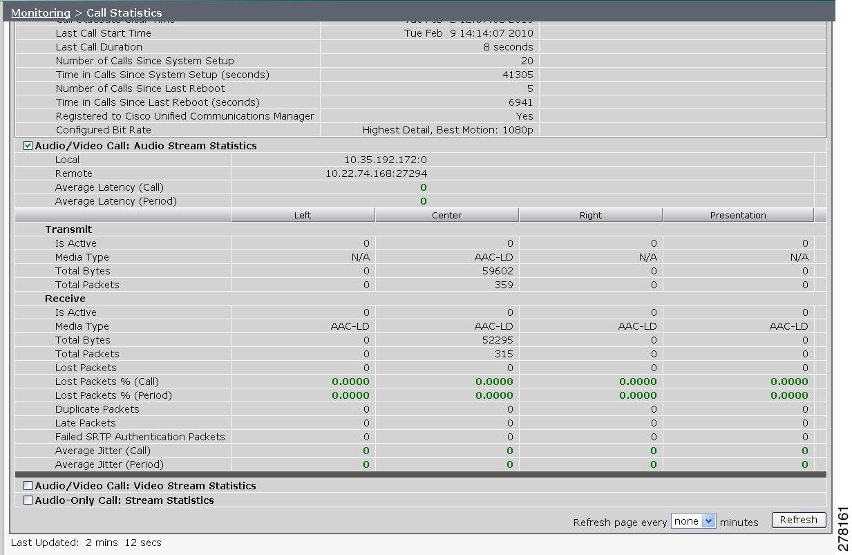
Additional statistics are listed for the following, as shown in Figure 2-6:
Transmit
•![]() Is Active
Is Active
•![]() Media Type
Media Type
•![]() Total Bytes
Total Bytes
•![]() Total Packets
Total Packets
Receive
•![]() Is Active
Is Active
•![]() Media Type
Media Type
•![]() Total Bytes
Total Bytes
•![]() Total Packets
Total Packets
•![]() Lost Packets
Lost Packets
•![]() Lost Packets % (Call)
Lost Packets % (Call)
•![]() Lost Packets % (Period)
Lost Packets % (Period)
•![]() Duplicate Packets
Duplicate Packets
•![]() Late Packets
Late Packets
•![]() Failed SRTP Authentication Packets
Failed SRTP Authentication Packets
•![]() Average Jitter (Call) (see jitter call)
Average Jitter (Call) (see jitter call)
•![]() Average Jitter (Period) (see jitter period)
Average Jitter (Period) (see jitter period)
Note ![]() For more information about jitter and packet loss, see the Understanding Jitter and Packet Loss Reporting section of the Cisco TelePresence System Message Guide on Cisco.com.
For more information about jitter and packet loss, see the Understanding Jitter and Packet Loss Reporting section of the Cisco TelePresence System Message Guide on Cisco.com.
Figure 2-6 Call Statistics - Transmit and Receive

Step 3 ![]() Set an interval for updating these reports by choosing the time from the Refresh drop-down menu. Choices, in minutes, include the following:
Set an interval for updating these reports by choosing the time from the Refresh drop-down menu. Choices, in minutes, include the following:
•![]() None (default)
None (default)
•![]() 1
1
•![]() 2
2
•![]() 5
5
•![]() 10
10
•![]() 13
13
•![]() 60
60
Step 4 ![]() Click Refresh to update the statistics immediately.
Click Refresh to update the statistics immediately.
Network Statistics
Use Network Statistics to view packet transmission statistics collected from the network. Statistics are listed in columns labeled as if you were looking at the back of the system. For example, on a CTS 3000 or CTS 3200, the labels would indicate statistics from the left, center, and right codecs.
To monitor network statistics:
Step 1 ![]() Choose Monitoring > Network Statistics. Statistics for your system appear, as shown in Figure 2-7.
Choose Monitoring > Network Statistics. Statistics for your system appear, as shown in Figure 2-7.
Figure 2-7 Network Statistics Window
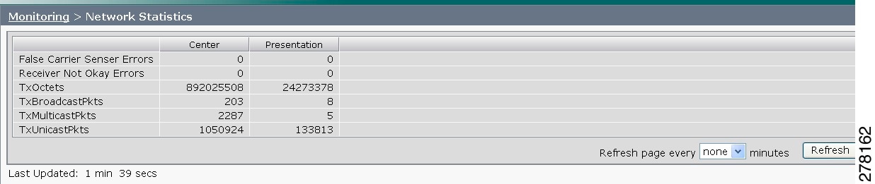
Step 2 ![]() Look for error counters that have been incremented since the last time you viewed these statistics. Statistic types include the following:
Look for error counters that have been incremented since the last time you viewed these statistics. Statistic types include the following:
•![]() False Carrier Sensor Errors
False Carrier Sensor Errors
•![]() Receiver Not Okay Errors
Receiver Not Okay Errors
•![]() Number of TxOctets
Number of TxOctets
•![]() Number of TxBroadcastPkts
Number of TxBroadcastPkts
•![]() Number of TxMulticastPkts
Number of TxMulticastPkts
•![]() Number of TxUnicastPkts
Number of TxUnicastPkts
Step 3 ![]() Set an interval for updating these reports by choosing the time from the Refresh drop-down menu. Choices, in minutes, include the following:
Set an interval for updating these reports by choosing the time from the Refresh drop-down menu. Choices, in minutes, include the following:
•![]() None (default)
None (default)
•![]() 1
1
•![]() 2
2
•![]() 5
5
•![]() 10
10
•![]() 13
13
•![]() 60
60
Step 4 ![]() Click Refresh to update the statistics immediately.
Click Refresh to update the statistics immediately.
Services Statuses
To check and, in some cases, restart network services, navigate to Monitoring > Services Statuses. You can restart the following services; to do so, click the Restart button next to the service to restart it:
•![]() Dynamic Host Control Protocol (DHCP) server
Dynamic Host Control Protocol (DHCP) server
•![]() Simple Network Management Protocol (SNMP) server
Simple Network Management Protocol (SNMP) server
•![]() Calling Services
Calling Services
•![]() The telephone server
The telephone server
Where to Go Next
Proceed to Chapter 3 "Device Information" to access the Cisco TelePresence System Administration interface.
 Feedback