- What's In This Guide
- Using the Cisco TelePresence System Administration Interface
- Understanding the Fields In the Cisco TelePresence System Administration Interface
- Device Information
- Configuring the Cisco TelePresence System
- Monitoring the Cisco TelePresence System
- Satellite Licenses for the Cisco TelePresence System
- Glossary
- Index
Administration Guide for Cisco TelePresence Software Release 1.10
Bias-Free Language
The documentation set for this product strives to use bias-free language. For the purposes of this documentation set, bias-free is defined as language that does not imply discrimination based on age, disability, gender, racial identity, ethnic identity, sexual orientation, socioeconomic status, and intersectionality. Exceptions may be present in the documentation due to language that is hardcoded in the user interfaces of the product software, language used based on RFP documentation, or language that is used by a referenced third-party product. Learn more about how Cisco is using Inclusive Language.
- Updated:
- April 3, 2013
Chapter: Configuring the Cisco TelePresence System
- Contents
- Configuring Cisco Unified Communications Manager for Your Cisco TelePresence System
- First Time Setup
- IP Settings
- Network Settings
- Cisco Unified Communications Manager Settings
- Address Book
- Telephony Settings
- SNMP Settings
- System Settings
- Security Settings
- Troubleshooting Your Configuration
- Upgrading CTS Codec Firmware
- Upgrading Software for Cisco TelePresence Touch 12
- Managing Passwords
- Configuring Your System for 802.1X Authentication
Configuring the Cisco TelePresence System
Contents
This chapter contains the following sections:
•![]() Configuring Cisco Unified Communications Manager for Your Cisco TelePresence System
Configuring Cisco Unified Communications Manager for Your Cisco TelePresence System
•![]() Cisco Unified Communications Manager Settings
Cisco Unified Communications Manager Settings
•![]() Troubleshooting Your Configuration
Troubleshooting Your Configuration
•![]() Upgrading Software for Cisco TelePresence Touch 12
Upgrading Software for Cisco TelePresence Touch 12
•![]() Configuring Your System for 802.1X Authentication
Configuring Your System for 802.1X Authentication
Configuring Cisco Unified Communications Manager for Your Cisco TelePresence System
Before you can use your system, you need to configure your system in Cisco Unified Communications Manager (Unified CM).
You can configure your system and complete all steps in this chapter prior to configuring your device in Unified CM, but you will not be able to complete any of the following actions until you register your device:
•![]() The Touch device cannot download its software from Unified CM and you receive an error in the logs.
The Touch device cannot download its software from Unified CM and you receive an error in the logs.
•![]() The Cisco TelePresence device cannot place or receive calls.
The Cisco TelePresence device cannot place or receive calls.
•![]() The device appears as a Cisco TelePresence System 1000 in the Cisco TelePresence Administration GUI.
The device appears as a Cisco TelePresence System 1000 in the Cisco TelePresence Administration GUI.
To configure your device in Unified CM, complete the following steps:
Step 1 ![]() Load the Cisco TelePresence Administration Software image on the Unified CM server.
Load the Cisco TelePresence Administration Software image on the Unified CM server.
For more information, refer to the following sections in the Cisco Telepresence Touch 12 Installation Guide:
•![]() If you are upgrading from a software version that prior to 1.7.4, follow the steps in the "Upgrading the CTS Software for Systems That Are Running Cisco TelePresence Software Versions Prior to 1.7.4" section.
If you are upgrading from a software version that prior to 1.7.4, follow the steps in the "Upgrading the CTS Software for Systems That Are Running Cisco TelePresence Software Versions Prior to 1.7.4" section.
•![]() If you are upgrading from a software version that is 1.7.4 or later, follow the steps in the "Upgrading the CTS Software for Systems That Are Running Cisco TelePresence Software Versions 1.7.4 and Above" section.
If you are upgrading from a software version that is 1.7.4 or later, follow the steps in the "Upgrading the CTS Software for Systems That Are Running Cisco TelePresence Software Versions 1.7.4 and Above" section.
Step 2 ![]() Register your system as a device in Unified CM. For more information, refer to the "Configuring a Cisco TelePresence Device" section in the Cisco Unified Communications Manager Configuration Guide for the Cisco TelePresence System.
Register your system as a device in Unified CM. For more information, refer to the "Configuring a Cisco TelePresence Device" section in the Cisco Unified Communications Manager Configuration Guide for the Cisco TelePresence System.
Step 3 ![]() Add the TFTP server for your Unified CM server to your system using the Cisco TelePresence Administration Software GUI. For more formation, refer to the "Cisco Unified Communications Manager Settings" of the Cisco TelePresence System Administration Guide for your software release.
Add the TFTP server for your Unified CM server to your system using the Cisco TelePresence Administration Software GUI. For more formation, refer to the "Cisco Unified Communications Manager Settings" of the Cisco TelePresence System Administration Guide for your software release.
For more information about configuring Unified CM with your Cisco TelePresence device, refer to the Cisco Unified Communications Manager Configuration Guide for the Cisco TelePresence System.
First Time Setup
To set up your Cisco TelePresence System (CTS) for the first time, you must first load the CTS Administration software and bootup the system.
This section contains the following information:
•![]() Loading CTS Administration Software
Loading CTS Administration Software
•![]() Configuring a Static IP Address for Networks That Do Not Use DHCP
Configuring a Static IP Address for Networks That Do Not Use DHCP
•![]() Configuring Unified CM For Networks with a Static IP Address
Configuring Unified CM For Networks with a Static IP Address
•![]() Configuring Your System After Initial Bootup
Configuring Your System After Initial Bootup
Loading CTS Administration Software
CTS Administration Software is factory-installed on each codec and loads during initial bootup. To boot up CTS Administration Software:
Step 1 ![]() Power on the PDU that is on the bottom of the CTS cabinet by turning the switch to the On position.
Power on the PDU that is on the bottom of the CTS cabinet by turning the switch to the On position.
Step 2 ![]() Turn on the codecs that are associated with your CTS device. The displays associated with each codec become active. CTS displays green check marks on all displays to show bootup progress. Bootup is complete when the system displays six check marks. Figure 4-1 shows a screen with five of the six check marks checked.
Turn on the codecs that are associated with your CTS device. The displays associated with each codec become active. CTS displays green check marks on all displays to show bootup progress. Bootup is complete when the system displays six check marks. Figure 4-1 shows a screen with five of the six check marks checked.

Tip ![]() Ignore any messages that indicate a communication error with the camera; this message indicates that the system has not yet downloaded the correct software or firmware.
Ignore any messages that indicate a communication error with the camera; this message indicates that the system has not yet downloaded the correct software or firmware.
Figure 4-1 Bootup (Five of Six Check Marks Checked)
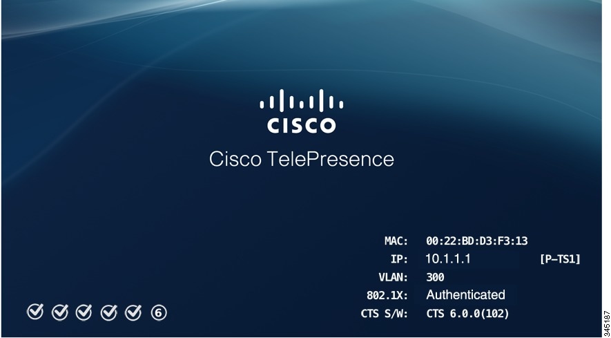

Note ![]() If the last check mark displayed is a red "X," there has been a compact flash error. If you receive this error, contact Cisco Technical Support.
If the last check mark displayed is a red "X," there has been a compact flash error. If you receive this error, contact Cisco Technical Support.
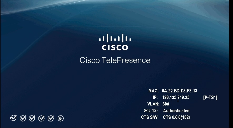
Step 3 ![]() After bootup completes, make a note of the IP and MAC address that displays on the center of the screen, as shown in Figure 4-2. Use this information to log in to the Cisco TelePresence System Administration interface. This IP address displays until you log in to Cisco TelePresence System Administration or use Secure Shell (SSH) to log in to your CTS device.
After bootup completes, make a note of the IP and MAC address that displays on the center of the screen, as shown in Figure 4-2. Use this information to log in to the Cisco TelePresence System Administration interface. This IP address displays until you log in to Cisco TelePresence System Administration or use Secure Shell (SSH) to log in to your CTS device.
Figure 4-2 System IP Address
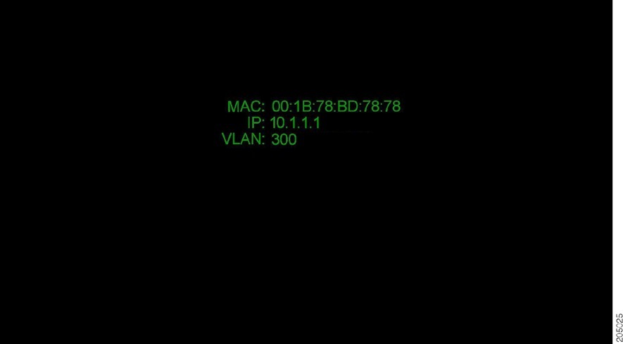
Note ![]() If the IP address that displays is 192.168.100.2, the CTS device could not contact the DHCP server or your system does not use DHCP. Do one of the following:
If the IP address that displays is 192.168.100.2, the CTS device could not contact the DHCP server or your system does not use DHCP. Do one of the following:
1. If your network does not use DHCP, configure a static IP address using the information in the "Configuring a Static IP Address for Networks That Do Not Use DHCP" section.
Configuring a Static IP Address for Networks That Do Not Use DHCP
If your network does not use DHCP, complete one of the following procedures to configure a static IP address for your Cisco TelePresence system.
See the following sections to manage static IP addresses:
•![]() Configuring a Static IP Address Using the Cisco TelePresence System GUI
Configuring a Static IP Address Using the Cisco TelePresence System GUI
•![]() Configuring a Static IP Address Using Command-Line Interface Commands
Configuring a Static IP Address Using Command-Line Interface Commands
Configuring a Static IP Address Using the Cisco TelePresence System GUI
To configure a static IP address using the Cisco TelePresence system GUI:
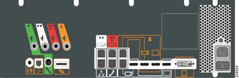
Step 1 ![]() Connect a DHCP-enabled PC to the secondary camera port of the primary codec. This connection is listed as the auxiliary network port in Figure 4-3.
Connect a DHCP-enabled PC to the secondary camera port of the primary codec. This connection is listed as the auxiliary network port in Figure 4-3.
Figure 4-3 Auxiliary Network Port Location
Step 2 ![]() Determine the IP address that the Cisco TelePresence system provided for your session.
Determine the IP address that the Cisco TelePresence system provided for your session.
Tip ![]() For Windows-based systems, you can see the IP address in the Support tab in the Local Area Connection Status window.
For Windows-based systems, you can see the IP address in the Support tab in the Local Area Connection Status window.
Step 3 ![]() Using Secure Shell SSH or another secure client program, start a CLI session with the Cisco TelePresence system using the IP address xxx.xxx.xxx.1,
Using Secure Shell SSH or another secure client program, start a CLI session with the Cisco TelePresence system using the IP address xxx.xxx.xxx.1,
Where:
xxx.xxx.xxx is the IP address that Cisco TelePresence provided for your session.
For example, if your determine that the Cisco Telepresence system provided an IP address of 10.1.0.2, enter the address 10.1.0.1.
By default, the username is admin and the password is cisco.
Step 4 ![]() Network services are started automatically. If needed, enter the following command to start network services:
Network services are started automatically. If needed, enter the following command to start network services:
utils service start Calling_Services
Step 5 ![]() Using a supported Internet browser, log in to the Cisco TelePresence system GUI with the IP address that you used in Step 3.
Using a supported Internet browser, log in to the Cisco TelePresence system GUI with the IP address that you used in Step 3.
Step 6 ![]() Enter the username and password when prompted. By default, the user is admin and the password is cisco.
Enter the username and password when prompted. By default, the user is admin and the password is cisco.
Step 7 ![]() Navigate to Configuration > IP Settings.
Navigate to Configuration > IP Settings.
Step 8 ![]() Change the DHCP Enabled setting to No.
Change the DHCP Enabled setting to No.
Step 9 ![]() Enter a static IP address, subnet mask, and IP gateway for your system into the fields. Optionally, enter DNS server(s) and the network domain name. Your system saves the changes and automatically restarts.
Enter a static IP address, subnet mask, and IP gateway for your system into the fields. Optionally, enter DNS server(s) and the network domain name. Your system saves the changes and automatically restarts.
Step 10 ![]() Continue to the "Configuring Unified CM For Networks with a Static IP Address" section to configure Unified CM for your system.
Continue to the "Configuring Unified CM For Networks with a Static IP Address" section to configure Unified CM for your system.
Configuring a Static IP Address Using Command-Line Interface Commands
To configure a static IP address using command-line commands:
Step 1 ![]() Connect a DHCP-enabled PC to the secondary camera port of the primary codec. This connection is listed as the auxiliary network port in Figure 4-3.
Connect a DHCP-enabled PC to the secondary camera port of the primary codec. This connection is listed as the auxiliary network port in Figure 4-3.
Step 2 ![]() Determine the IP address that the Cisco TelePresence system provided for your session.
Determine the IP address that the Cisco TelePresence system provided for your session.
Tip ![]() For Windows-based systems, you can see the IP address in the Support tab in the Local Area Connection Status window.
For Windows-based systems, you can see the IP address in the Support tab in the Local Area Connection Status window.
Step 3 ![]() Using Secure Shell SSH or another secure client program, start a CLI session with the TelePresence system using the IP address xxx.xxx.xxx.1,
Using Secure Shell SSH or another secure client program, start a CLI session with the TelePresence system using the IP address xxx.xxx.xxx.1,
Where:
xxx.xxx.xxx is the IP address that Cisco TelePresence provided for your session.
For example, if your determine that the Cisco Telepresence system provided an IP address of 10.1.0.2, enter the address 10.1.0.1.
By default, the username is admin and the password is cisco.
Step 4 ![]() Enter the following command to configure a static network IP address:
Enter the following command to configure a static network IP address:
set network IP static ip-address ip-subnet ip-gateway [dns-address1][dns-address2][domain-name]
Where:
ip-address is the IP address of the system
ip-subnet is the IP subnet mask of the system
ip-gateway is the IP gateway of the system
dns-address1 is the IP address of DNS server 1 (Optional)
dns-address2 is the IP address of DNS server 2 (Optional)
domain-name is the domain name for the network (Optional)
Step 5 ![]() Continue to the "Configuring Unified CM For Networks with a Static IP Address" section to configure Unified CM for your system.
Continue to the "Configuring Unified CM For Networks with a Static IP Address" section to configure Unified CM for your system.
Command Example
The following example gives the Cisco TelePresence system with an IP address of 10.0.0.2, a subnet of 255.255.255.0, a gateway of 10.0.0.1, a DNS server of 172.16.1.5, and a domain name of cisco.com:
admin:set network IP static 10.0.0.2 255.255.255.0 10.0.0.1 172.16.1.5 cisco.com
ip address successfully set
system restarting...
Configuring Unified CM For Networks with a Static IP Address
If your system uses a static IP address, manually specify the IP address of your Cisco Unified Communications Server by completing the following steps:
Step 1 ![]() Navigate to Configuration > Unified CM Settings.
Navigate to Configuration > Unified CM Settings.
Step 2 ![]() In the Use Configuration TFTP Server area, click Specify.
In the Use Configuration TFTP Server area, click Specify.
Step 3 ![]() In the TFTP Server 1 area, specify the IP address of the Unified CM server.
In the TFTP Server 1 area, specify the IP address of the Unified CM server.
Step 4 ![]() (Optional) If the system uses any additional Unified CM servers, specify those in the TFTP Server 2 through TFTP Server 4 area.
(Optional) If the system uses any additional Unified CM servers, specify those in the TFTP Server 2 through TFTP Server 4 area.
Step 5 ![]() Click Apply.
Click Apply.
Configuring Your System After Initial Bootup
After successful bootup, the CTS Administration Software loads. When the CTS Administration software completes loading, the Cisco Unified IP phone displays a welcome message that shows the system IP address. The welcome screen only appears the first time the system is booted up after initial installation or after a factory reset.
Note ![]() The telephone displays a directory number of 7000, but the telephone is not yet registered and does not function.
The telephone displays a directory number of 7000, but the telephone is not yet registered and does not function.
Before You Begin
If you have not already done so, configure Cisco Unified Communications Manager. See the Cisco Unified Communications Manager Configuration Guide for the Cisco TelePresence System.
To continue your initial setup:
Step 1 ![]() From the CTS Cisco Unified IP phone welcome page, press Next. The system reboots.
From the CTS Cisco Unified IP phone welcome page, press Next. The system reboots.
Note ![]() The system might reboot several times during the initial startup process.
The system might reboot several times during the initial startup process.
Step 2 ![]() Open a browser on a computer that is connected to the network.
Open a browser on a computer that is connected to the network.
Step 3 ![]() In the URL field, type in your IP address and press Enter. The browser launches the Cisco TelePresence System Administration interface.
In the URL field, type in your IP address and press Enter. The browser launches the Cisco TelePresence System Administration interface.
Note ![]() If you need to obtain the IP address, complete the following steps:
If you need to obtain the IP address, complete the following steps:
a. ![]() On the CTS Cisco Unified IP phone, press the Manual softkey at the bottom of the screen.
On the CTS Cisco Unified IP phone, press the Manual softkey at the bottom of the screen.
b. ![]() Locate "Info" at the bottom of the screen and press the Info soft key.
Locate "Info" at the bottom of the screen and press the Info soft key.
c. ![]() Scroll down to the IP Address listing and copy the address.
Scroll down to the IP Address listing and copy the address.
Step 4 ![]() Log in to the system by entering the following information:
Log in to the system by entering the following information:
•![]() Username: admin (case sensitive)
Username: admin (case sensitive)
•![]() Password: cisco (case sensitive)
Password: cisco (case sensitive)
Note ![]() You can change your password in Unified CM. See the Cisco Unified Communications Manager Configuration Guide for the Cisco TelePresence System.
You can change your password in Unified CM. See the Cisco Unified Communications Manager Configuration Guide for the Cisco TelePresence System.
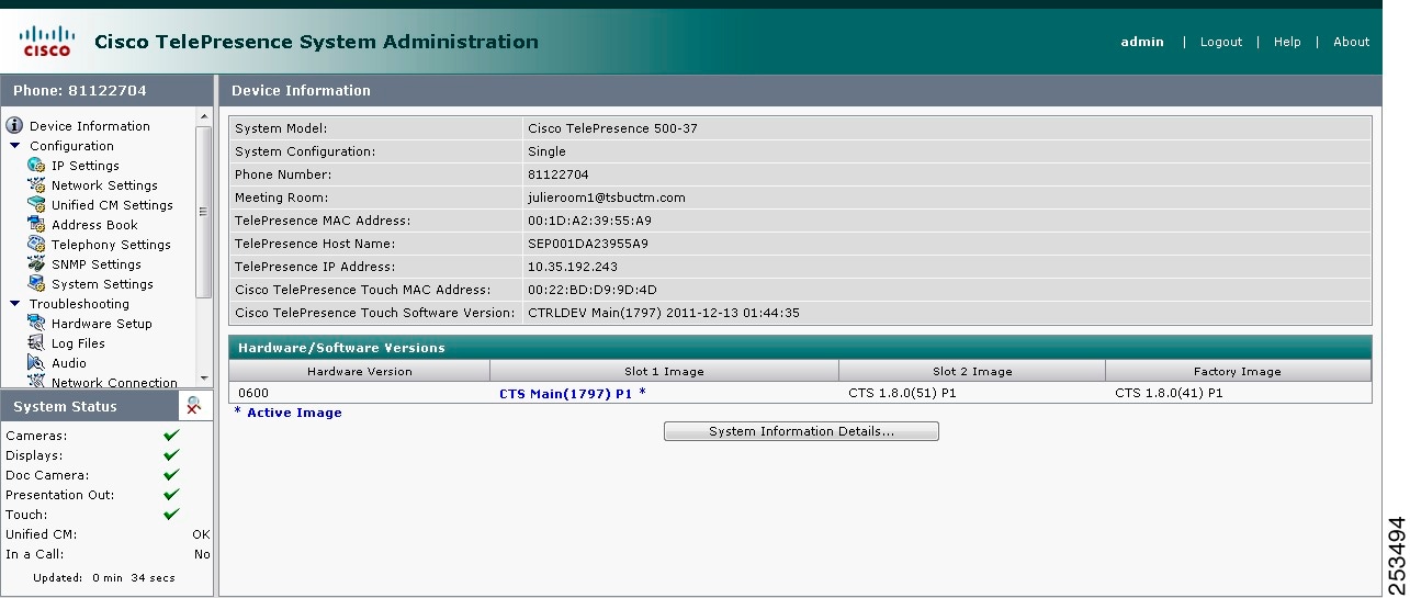
Step 5 ![]() Click Login. The Device Information window appears, as shown in Figure 4-4.
Click Login. The Device Information window appears, as shown in Figure 4-4.
Figure 4-4 Device Information Screen
Note ![]() See the "Upgrading CTS Codec Firmware" section for information about upgrading to new CTS firmware releases.
See the "Upgrading CTS Codec Firmware" section for information about upgrading to new CTS firmware releases.
Step 6 ![]() Continue to the following sections to configure your system:
Continue to the following sections to configure your system:
•![]() Cisco Unified Communications Manager Settings
Cisco Unified Communications Manager Settings
IP Settings
The IP Settings window displays the Cisco TelePresence System (CTS) MAC address and hostname and you can view and manage the following:
•![]() DHCP—Select a static IP address, which allows the Cisco IP phone to be configured so that the system recognizes it as a device in the network, rather than a router.
DHCP—Select a static IP address, which allows the Cisco IP phone to be configured so that the system recognizes it as a device in the network, rather than a router.
•![]() Domain name
Domain name
•![]() IP Address
IP Address
•![]() Default gateway
Default gateway
•![]() DNS servers.
DNS servers.
To view and manage IP settings:
Step 1 ![]() Choose Configuration > IP Settings. The IP Settings window appears, as shown in Figure 4-5 (DHCP Enabled) and Figure 4-5 (DHCP Not Enabled).
Choose Configuration > IP Settings. The IP Settings window appears, as shown in Figure 4-5 (DHCP Enabled) and Figure 4-5 (DHCP Not Enabled).
Figure 4-5 CTS IP Settings - DHCP Enabled
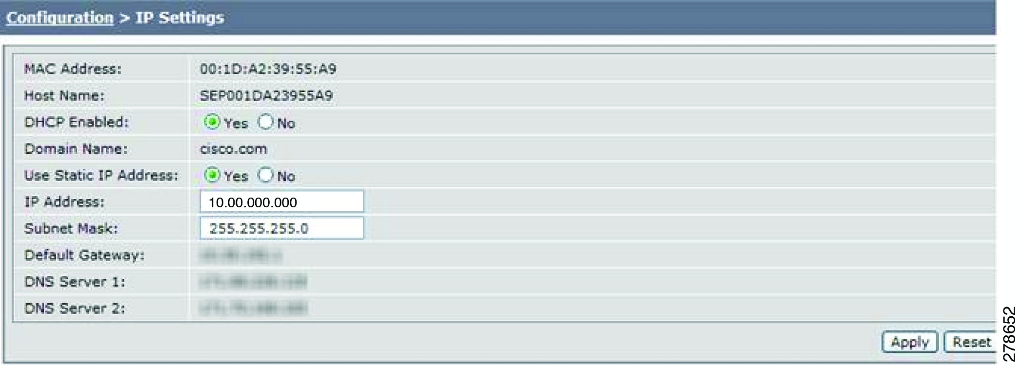
Figure 4-6 CTS IP Settings - DHCP Not Enabled

Step 2 ![]() Configure settings for the Cisco TelePresence System uplink to your network using the information in Table 4-1 as a guide. The Cisco TelePresence System can be configured in the following ways:
Configure settings for the Cisco TelePresence System uplink to your network using the information in Table 4-1 as a guide. The Cisco TelePresence System can be configured in the following ways:
•![]() Pure dynamic—Uses DHCP for everything.
Pure dynamic—Uses DHCP for everything.
•![]() Pure static—Uses static settings for everything.
Pure static—Uses static settings for everything.
•![]() Hybrid—Uses static settings for the IP Address, subnet mask and gateway, but uses DHCP for name servers and other options like Option 150 for the Unified CM TFTP servers.
Hybrid—Uses static settings for the IP Address, subnet mask and gateway, but uses DHCP for name servers and other options like Option 150 for the Unified CM TFTP servers.
Tip ![]() When you make a change in any of the Configuration > IP Settings fields, the Apply and Reset buttons are activated.
When you make a change in any of the Configuration > IP Settings fields, the Apply and Reset buttons are activated.
Step 3 ![]() Click Apply to register new or modified settings.
Click Apply to register new or modified settings.
Step 4 ![]() Click Reset to restore the original settings.
Click Reset to restore the original settings.
Note ![]() All codecs on the system must be connected and enabled for the factory reset to complete. To register a device, see the "Optional Hardware" section of the Cisco Unified Communications Manager Configuration Guide for the Cisco TelePresence System.
All codecs on the system must be connected and enabled for the factory reset to complete. To register a device, see the "Optional Hardware" section of the Cisco Unified Communications Manager Configuration Guide for the Cisco TelePresence System.
Network Settings
You can view or configure the following settings in the Network Settings window:
Operational VLAN ID
This field shows a display-only VLAN ID that is standard for networks with a Cisco Unified IP phone.
Administrative VLAN ID
The CTS must have a VLAN membership ID before it can proceed with a DHCP request for an IP address.
To view or configure the administrative VLAN ID:
Step 1 ![]() Choose Configuration > Network Settings.
Choose Configuration > Network Settings.
Step 2 ![]() Enter an administrative VLAN ID for Cisco TelePresence in this field.
Enter an administrative VLAN ID for Cisco TelePresence in this field.
Note ![]() The Apply and Reset buttons become active when a value is entered in this field.
The Apply and Reset buttons become active when a value is entered in this field.
Step 3 ![]() Click Apply to register a new or modified setting.
Click Apply to register a new or modified setting.
Step 4 ![]() Click Reset to restore the administrative VLAN ID setting displayed when you opened this window.
Click Reset to restore the administrative VLAN ID setting displayed when you opened this window.
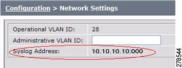
Syslog Address
This field shows the display-only syslog address that is standard for networks with a Cisco Unified IP phone, as shown in Figure 4-7.
Figure 4-7 Network Settings Syslog Address
Note ![]() You must also configure the External Syslog Address in the Product Specific Configuration Layout field for your CTS. See the Cisco Unified Communications Configuration Guide for the Cisco TelePresence System.
You must also configure the External Syslog Address in the Product Specific Configuration Layout field for your CTS. See the Cisco Unified Communications Configuration Guide for the Cisco TelePresence System.
Cisco Unified Communications Manager Settings
To specify TFTP server locations and view a list of available settings for this Cisco TelePresence system:
Step 1 ![]() Choose Configuration > Cisco Unified Communications Manager Settings. The Cisco Unified Communications Manager Settings window appears, as shown in Figure 4-8.
Choose Configuration > Cisco Unified Communications Manager Settings. The Cisco Unified Communications Manager Settings window appears, as shown in Figure 4-8.
Figure 4-8 Cisco Unified Communications Manager Settings
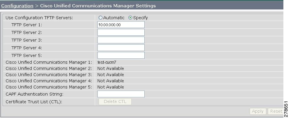
Step 2 ![]() Configure Unified CM settings using the information in Table 4-2.
Configure Unified CM settings using the information in Table 4-2.
Note ![]() The Apply and Reset buttons become active when a value is entered in this field.
The Apply and Reset buttons become active when a value is entered in this field.
Step 3 ![]() Click Apply to register new or modified settings.
Click Apply to register new or modified settings.
Step 4 ![]() Click Reset to restore the original settings.
Click Reset to restore the original settings.
Note ![]() All codecs on the system must be connected and enabled for the factory reset to complete. To register a device, see the "Optional Hardware" and "Troubleshooting the Cisco TelePresence Configuration" sections of the Cisco Unified Communications Manager Configuration Guide for the Cisco TelePresence System.
All codecs on the system must be connected and enabled for the factory reset to complete. To register a device, see the "Optional Hardware" and "Troubleshooting the Cisco TelePresence Configuration" sections of the Cisco Unified Communications Manager Configuration Guide for the Cisco TelePresence System.
Related Information
See the following documentation for more information about Unified CM:
•![]() Cisco Unified Communications Manager Configuration Guide for the Cisco TelePresence System
Cisco Unified Communications Manager Configuration Guide for the Cisco TelePresence System
•![]() Cisco Unified Communications Manager (CallManager) Documentation Roadmaps
Cisco Unified Communications Manager (CallManager) Documentation Roadmaps
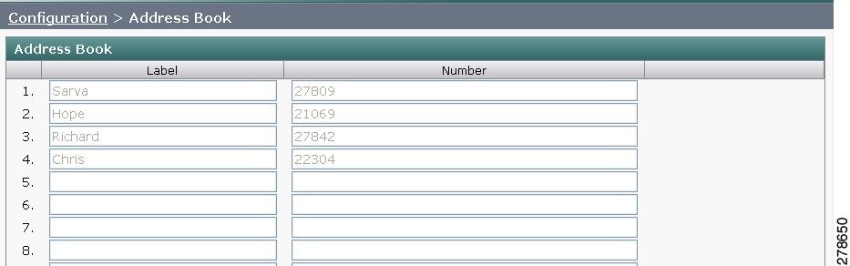
Address Book
The Address Book window displays read-only entries that have been set during Cisco Unified Communications Manager (Unified CM) configuration. You can create listings for up to 40 meeting rooms.
To view the phone list of Cisco TelePresence system-enabled meeting rooms:
Step 1 ![]() Choose Configuration > Address Book. The Address Book window appears, as shown in Figure 4-9.
Choose Configuration > Address Book. The Address Book window appears, as shown in Figure 4-9.
Figure 4-9 CTS Address Book
Step 2 ![]() Use Unified CM to make changes to the Address Book. See the Cisco Unified Communications Manager Configuration Guide for the Cisco TelePresence System.
Use Unified CM to make changes to the Address Book. See the Cisco Unified Communications Manager Configuration Guide for the Cisco TelePresence System.
Telephony Settings
The Telephony Settings window displays read-only information about the telephony settings for the Cisco TelePresence System that were set in the Unified CM.
To view entries in the Telephony Settings window:
Step 1 ![]() Choose Configuration > Telephony Settings. The Telephony Settings window appears, as shown in
Choose Configuration > Telephony Settings. The Telephony Settings window appears, as shown in
Figure 4-10 CTS Telephony Settings
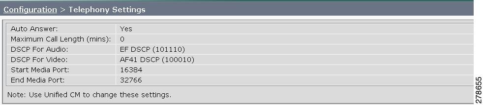
Step 2 ![]() View the telephony settings described in Table 4-3.
View the telephony settings described in Table 4-3.
Step 3 ![]() Use Unified CM to make changes to Telephony Settings. See the Cisco Unified Communications Manager Configuration Guide for the Cisco TelePresence System.
Use Unified CM to make changes to Telephony Settings. See the Cisco Unified Communications Manager Configuration Guide for the Cisco TelePresence System.
SNMP Settings
The Simple Network Management Protocol (SNMP) Settings window displays read-only information about the SNMP settings for the Cisco TelePresence System that were set in Unified CM configuration.
To view SNMP settings:
Step 1 ![]() Choose Configuration > SNMP Settings. The SNMP Settings window appears, as shown in Figure 4-11.
Choose Configuration > SNMP Settings. The SNMP Settings window appears, as shown in Figure 4-11.
Figure 4-11 Verify SNMP Settings

Step 2 ![]() View the SNMP settings fields described in Table 4-4.
View the SNMP settings fields described in Table 4-4.
|
|
|
|---|---|
Engine ID |
Identifies the local or remote SNMP engine. The remote agent SNMP engine ID and user password are used to compute authentication and privacy digests. |
SNMP Configuration |
Parameters that access the SNMP server associated with this Cisco TelePresence System. Unified CM for CTS supports SNMP Version 2c and Version 3. SNMP fields displayed in this window reflect the configured SNMP version. The following fields are included: • • • • • • • • • |
Trap Receiver Configuration |
SNMP settings for the receiver to which this Cisco TelePresence system will send traps. The following information is shown for Traps 1 through 5: • • • • • • • |
Step 3 ![]() Use Unified CM to make changes to the SNMP settings. See the Cisco Unified Communications Manager Configuration Guide for the Cisco TelePresence System.
Use Unified CM to make changes to the SNMP settings. See the Cisco Unified Communications Manager Configuration Guide for the Cisco TelePresence System.
Related Information
For more information about SNMP, see the following information on Cisco.com:
•![]() MIBs, RFCs, and SNMP Trap Messages for the Cisco TelePresence System
MIBs, RFCs, and SNMP Trap Messages for the Cisco TelePresence System
•![]() Simple Network Management Protocol (SNMP) home page.
Simple Network Management Protocol (SNMP) home page.
System Settings
The System Settings window displays read-only information about the system settings for the Cisco TelePresence System that were set in Unified CM configuration.
To view system settings:
Step 1 ![]() Choose Configuration > System Settings. The System Settings window appears, as shown in Figure 4-12.
Choose Configuration > System Settings. The System Settings window appears, as shown in Figure 4-12.
Figure 4-12 CTS System Settings
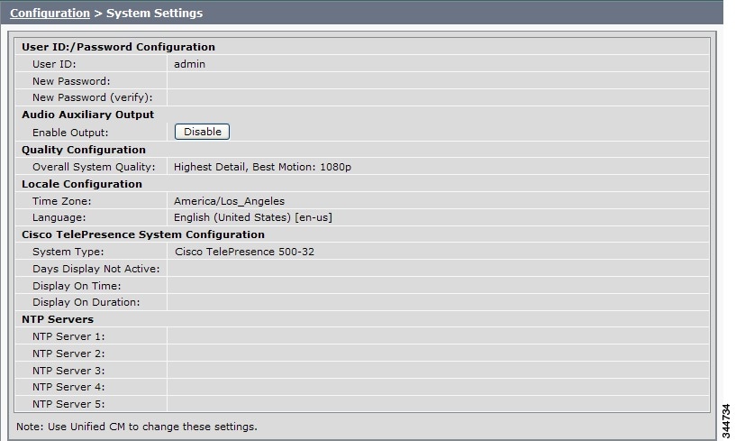
Step 2 ![]() View the system settings information described in Table 4-5.
View the system settings information described in Table 4-5.
|
|
|
|---|---|
|
|
|
User ID New Password New Password (verify) |
Displays username and password. Note |
|
|
|
|
|
|
Overall System Quality |
This field displays the system bandwidth and screen resolution. The bandwidth is the maximum negotiated video bandwidth for a CTS call. A higher bandwidth increases video quality. Choose from the following: • • • • • • • |
|
|
|
Time Zone |
Displays the configured time zone for your area of the world from the drop-down menu. |
Language |
Displays the configured language for CTS. Note |
|
|
|
System Type |
Identifies the CTS model. You must select the CTS device type from the list to upgrade your CTS software. |
Days Display Not Active |
Specifies the days of the week that the Cisco TelePresence system display remains off by default. Choose Monday through Sunday. Default is Sunday and Saturday. |
Display On Time |
Specifies the time of day that the Cisco TelePresence system display(s) will remain on after being turned on, if CCM is configured. Times are displayed in a 24-hour format where 00:00 indicates 12:00 midnight and 23:59 indicates 11:59 pm. Default is 07:30. If you clear the default value so that the field is blank, the display(s) will turn off after the completion of each call. |
Display On Duration |
Specifies the length of time the Cisco TelePresence system display(s) will remain on if a "Display On Time" value is defined. Times are displayed in a 24-hour format, where 1:30 indicates one hour and thirty minutes; the maximum value is 24:00 (24 hours). Default is 10:30. If you clear the default value so that the field is blank, then the display will turn off at 11:59 pm. |
Note |
|
|
|
|
NTP Server 1 through 5 |
Required. Network Time Protocol (NTP) is used to synchronize the clocks on Cisco IP telephony servers with an external network time server that uses NTP. You can have up to five IP addresses for Network Time Protocol servers. Note |
Step 3 ![]() Use Unified CM to make changes to the system settings. See the Cisco Unified Communications Manager Configuration Guide for the Cisco TelePresence System for more information.
Use Unified CM to make changes to the system settings. See the Cisco Unified Communications Manager Configuration Guide for the Cisco TelePresence System for more information.
Security Settings
The Security Settings window enables you to download a Manufacturing Installed Certificate (MIC) key or Locally Significant Certificate (LSC) certificate for 802.1X authentication. For more information about 802.1X authentication, see "Configuring Your System for 802.1X Authentication" section.
To download a MIC key or LSC certificate:
Step 1 ![]() Choose Configuration > Security Settings. The Security Settings window appears, as shown in Figure 4-13.
Choose Configuration > Security Settings. The Security Settings window appears, as shown in Figure 4-13.
Figure 4-13 Security Settings
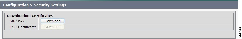
Step 2 ![]() To download a certificate, click the Download button next to it.
To download a certificate, click the Download button next to it.
Note ![]() If a certificate is not present in the system, the Download button next to it is dimmed.
If a certificate is not present in the system, the Download button next to it is dimmed.
Step 3 ![]() Save the certificate to your hard disk.
Save the certificate to your hard disk.
Troubleshooting Your Configuration
Use the information in Table 4-6 to help you troubleshoot your configuration.
Before You Begin
First check that the following conditions have been met:
•![]() Power has been applied.
Power has been applied.
•![]() The Cisco TelePresence System has been installed and configured according to the instructions in Cisco TelePresence System Assembly Guides.
The Cisco TelePresence System has been installed and configured according to the instructions in Cisco TelePresence System Assembly Guides.
•![]() Unified CM has been configured to support the Cisco TelePresence System as described in the Cisco Unified Communications Manager Configuration Guide for Cisco TelePresence System.
Unified CM has been configured to support the Cisco TelePresence System as described in the Cisco Unified Communications Manager Configuration Guide for Cisco TelePresence System.
|
|
|
|
|---|---|---|
Selecting the Test Connection function on the Unified CM web page results in an error. |
Incorrect Cisco TelePresence Manager Application User credentials: • |
1. 2. |
The Cisco TelePresence unit does not register. |
Cisco TelePresence System could be unknown: • • • |
1. 2. |
The Cisco Unified IP Phone 7975 does not register. |
Phone could be unknown: • • • • |
Verify Phone Registration—Log in to the Unified CM administration interface. Click the IP address and verify phone registration. • |
The phone does not display the Cisco TelePresence idle screen. |
• – – – • – – |
1. 2. 3. |
CTS does not auto answer |
• • |
The CTS rings and auto-answers a call based on how these features were configured in Unified CM. If the call is connected as audio only, check your IP phone configuration and make sure the "Disable Speaker/Headset" box is checked. To disable the IP phone speaker/headset: 1. 2. 3. 4. 5. – – 6. 7. See the Cisco Unified Communications Manager Configuration Guide for Cisco TelePresence System for more information. |
Call terminates prematurely |
DSP failure due to incompatible CTS software version. |
CTS devices are backward compatible up to two CTS Software Releases. You may want to upgrade your software. |
• • • • • |
The Cisco TelePresence Recording Server (CTRS) Studio Mode recording feature is not working and the room has been unsubscribed. One or more of the rooms in a conference does not support the feature. |
Check Room View on CTS-Man to verify whether a CTS device is capable of supporting the features in a specific room. Then check your Unified CM configuration settings to configure the device. See the Cisco Unified Communications Manager Configuration Guide for the Cisco TelePresence System for more information. |
Upgrading CTS Codec Firmware
Note ![]() Upgrades should only be performed at night or during minimal Cisco TelePresence usage times. An upgrade takes up to 30 minutes to complete.
Upgrades should only be performed at night or during minimal Cisco TelePresence usage times. An upgrade takes up to 30 minutes to complete.
The procedure to upgrade CTS firmware is the same as the firmware upgrade procedure for the Cisco Unified CM IP phones. See the Uploading Files to the Cisco Unified CM TFTP Directory section of the Cisco Unified Communications Manager Configuration Guide for the Cisco TelePresence System for complete instructions.
To download CTS firmware:
Step 1 ![]() Log into the Download Software Select a Product page on Cisco.com:
Log into the Download Software Select a Product page on Cisco.com:
http://www.cisco.com/cisco/software/navigator.html
The Tools & Resources Download Software appears.
Step 2 ![]() Expand the Cisco TelePresence System folder and open the Cisco TelePresence System sub folder. A list of CTS devices appears.
Expand the Cisco TelePresence System folder and open the Cisco TelePresence System sub folder. A list of CTS devices appears.
Step 3 ![]() Select your CTS device
Select your CTS device
Step 4 ![]() Upload the firmware file to the TFTP directory of your Unified CM TFTP server.
Upload the firmware file to the TFTP directory of your Unified CM TFTP server.
Step 5 ![]() Restart the TFTP server.
Restart the TFTP server.
Step 6 ![]() Change the firmware filename for the system(s) that you want to upgrade (either via the Device Defaults page, or on a per system basis) in the Cisco Unified CM Administration interface.
Change the firmware filename for the system(s) that you want to upgrade (either via the Device Defaults page, or on a per system basis) in the Cisco Unified CM Administration interface.
Step 7 ![]() Click the Restart button in Unified CM for the device(s) that you want to upgrade.
Click the Restart button in Unified CM for the device(s) that you want to upgrade.
Upgrading Software for Cisco TelePresence Touch 12
See the following important software upgrade information in the Upgrading From a Cisco Unified IP Phone to a Cisco TelePresence Touch 12 document at the following URL:
http://www.cisco.com/en/US/docs/telepresence/peripherals/cisco_touch/installation/cisco_touch_installation_upgrade.html
Managing Passwords
This section contains the following information about managing and troubleshooting password issues on the Cisco TelePresence System (CTS):
•![]() Resetting Your CTS Codec Password
Resetting Your CTS Codec Password
•![]() Configuring Your System for 802.1X Authentication
Configuring Your System for 802.1X Authentication
Resetting Your CTS Codec Password
Note ![]() You must be in the Cisco TelePresence room to read the newly requested passcode that shows on the main display.
You must be in the Cisco TelePresence room to read the newly requested passcode that shows on the main display.
At each point where the pwrecovery account requires input, the program will wait up to 60 seconds. If nothing is entered, the system will inform you that the entry took too long and will exit.
If you encounter any difficulty, open a case with Technical Assistance Center (TAC) via the Internet at http://tools.cisco.com/ServiceRequestTool/create/, or contact your Cisco technical support representative and provide the representative with the information you have gathered about the problem.
Before You Begin
Make sure that the CTS is not in a call, and that there is only one instance of someone trying to reset the password, otherwise the session will abort.
Procedure
To reset your CTS codec password:
Step 1 ![]() SSH into the codec from your laptop.
SSH into the codec from your laptop.
Step 2 ![]() Login with the following:
Login with the following:
•![]() Username: pwrecovery
Username: pwrecovery
•![]() Password: pwreset
Password: pwreset
The following message appears in the SSH client window:
Example 4-1 Welcome to Password Reset
dhcp-249:~ $ ssh pwrecovery@10.00.00.100
pwrecovery@10.00.00.100's password:
***********************************************
***********************************************
** **
** Welcome to password reset **
** **
***********************************************
***********************************************

Do you want to continue ? (y/n):y
Preparing the system...
Please enter the passcode:
Step 3 ![]() The system will ask whether you want to continue. Type Y then return to continue
The system will ask whether you want to continue. Type Y then return to continue
Note ![]() If desired, type any other key then return to exit.
If desired, type any other key then return to exit.
This system will now prepare for password reset and prompt you for a passcode. The new passcode is displayed on the CTS main display, as shown in the following example:
Password reset is now being run
Passcode: 919175
Note ![]() The passcode is a randomly generated number and will be different for each login attempt. If you enter the wrong passcode, the system will inform you that the passcode was incorrect and will exit, as shown in the following example. If this happens, repeat Step 1 and Step 2.
The passcode is a randomly generated number and will be different for each login attempt. If you enter the wrong passcode, the system will inform you that the passcode was incorrect and will exit, as shown in the following example. If this happens, repeat Step 1 and Step 2.
Example 4-2 Invalid Password Reset Request
Do you want to continue ? (y/n):y
Preparing the system...
Please enter the passcode:12345
Sorry that was an invalid passcode...
Logging off
Connection to 10.00.00.100 closed.
dhcp-249:~ $
When you enter the correct passcode, the CTS will then reset the administration account name and password to the system defaults. The following example shows successful password reset information:
Example 4-3 Successful Password Reset Request
Please enter the passcode:507530
resetting admin name and password
stopping any existing admin session
admin account and password reset to default
success in applying security rules
Logging off
Connection to 10.00.00.100 closed.
dhcp-249:~ $
Note ![]() If you are using the CTS with a Cisco Unified Communications Manager, the next time you perform a "Refresh" or "Reset" from the Unified CM, the administration account name and password will be reconfigured to the values specified in the Unified CM device page.
If you are using the CTS with a Cisco Unified Communications Manager, the next time you perform a "Refresh" or "Reset" from the Unified CM, the administration account name and password will be reconfigured to the values specified in the Unified CM device page.
Configuring Your System for 802.1X Authentication
This chapter describes how to set up, monitor, and troubleshoot 802.1X authentication in the Cisco TelePresence System:
•![]() IEEE 802.1X Authentication Overview
IEEE 802.1X Authentication Overview
•![]() Setting up 802.1X Authentication
Setting up 802.1X Authentication
•![]() Checking the CTS 802.1x Authentication Status
Checking the CTS 802.1x Authentication Status
•![]() Troubleshooting 802.1x Authentication Issues
Troubleshooting 802.1x Authentication Issues
IEEE 802.1X Authentication Overview
802.1X is an IEEE standard for port-based network access control. It offers the capability to permit or deny network connectivity, control Virtual LAN (VLAN) access, and apply traffic policy, based on user or machine identity.
802.1X permits or denies device access to the network by using authentication. Ethernet switch ports can be enabled dynamically based on the identity of the device that connects to it. Devices which are not authenticated cannot gain access to the network.
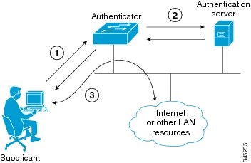
802.1X Authentication Components
802.1X authentication involves the following three network devices:
•![]() A supplicant: a client device (such as a laptop or endpoint) that attempts to access a LAN/Wireless LAN (WLAN), or the software that runs on this device and that provides credentials to the authenticator.
A supplicant: a client device (such as a laptop or endpoint) that attempts to access a LAN/Wireless LAN (WLAN), or the software that runs on this device and that provides credentials to the authenticator.
•![]() An authenticator: a network device (such as an Ethernet switch or wireless access point) that acts as an access point to a protected network. For 802.1X authentication, the supplicant provides network credentials, such as user name, password, digital security certificate, or a combination of these, to the authenticator. The authenticator then forwards the credentials to the authentication server for verification.
An authenticator: a network device (such as an Ethernet switch or wireless access point) that acts as an access point to a protected network. For 802.1X authentication, the supplicant provides network credentials, such as user name, password, digital security certificate, or a combination of these, to the authenticator. The authenticator then forwards the credentials to the authentication server for verification.
•![]() An authentication server: a server (such as Cisco Secure Access Control Server) that guards the protected network. For 802.1X authentication, the authentication server receives the supplicant's network credentials from the authenticator and verifies the supplicant's identity. Then the supplicant is able to access the resources located on the network.
An authentication server: a server (such as Cisco Secure Access Control Server) that guards the protected network. For 802.1X authentication, the authentication server receives the supplicant's network credentials from the authenticator and verifies the supplicant's identity. Then the supplicant is able to access the resources located on the network.
Figure 4-14 Diagram of 802.1X Authentication Process
Authenticating Your System
Your Cisco TelePresence System is equipped to function as an 802.1X-compliant supplicant. 802.1X authentication is enabled by default.
Note ![]() Cisco recommends that you configure your switch port (or authenticator) for multi-domain mode.
Cisco recommends that you configure your switch port (or authenticator) for multi-domain mode.
Setting up 802.1X Authentication
This section describes the steps you perform to set up 802.1x authentication, and includes the following topics:
•![]() Authenticating the Cisco TelePresence System Using a Security Certificate (MIC or LSC)
Authenticating the Cisco TelePresence System Using a Security Certificate (MIC or LSC)
•![]() Examining the Security Certificate in the Cisco TelePresence System
Examining the Security Certificate in the Cisco TelePresence System
Note ![]() In order to complete 802.1X authentication, you must use a port that is not already enabled for 802.1X.
In order to complete 802.1X authentication, you must use a port that is not already enabled for 802.1X.
Authenticating the Cisco TelePresence System Using a Security Certificate (MIC or LSC)
When the Cisco TelePresence System receives an authentication challenge from an Authenticator, the system responds with either the Manufacturing Installed Certificate (MIC) or the Locally Significant Certificate (LSC). When both the MIC and LSC are installed, the system uses the LSC to authenticate. If the LSC is not installed, Cisco TelePresence System uses the MIC, as the MIC is built into the system by the manufacturer.
The LSC provides greater security because it creates a public key infrastructure (PKI) that is unique to each system. To authenticate the codec using the LSC, you must install it on your system manually by using the Certificate Authority Proxy Function (CAPF) in Cisco Unified Communication Manager (CUCM). For more information, see the "Installing the LSC" section.
Installing the LSC
To install the LSC, refer to the "Deploying Locally Significant Certificates" section found in the IP Telephony for 802.1X Design Guide.
Examining the Security Certificate in the Cisco TelePresence System
You may want to examine the security certificate (MIC or LSC) on an 802.1X-authenticated system in order to verify that the certificates are valid, not expired, and issued by the CAPF.
To examine the security certificate in your Cisco TelePresence System, you may download a copy of the certificate to your own system by using either of two methods:
•![]() Downloading the Security Certificate Using the CLI
Downloading the Security Certificate Using the CLI
•![]() Downloading the Security Certificate Using the GUI
Downloading the Security Certificate Using the GUI
Downloading the Security Certificate Using the CLI
To download the MIC or LSC using the CLI, complete the following steps:
Step 1 ![]() Log in to the CLI.
Log in to the CLI.
Step 2 ![]() Enter the following command: file get cert {cert-type} {SCP-user} {SCP-password} {IP-address-or-hostname} {file-save-location}
Enter the following command: file get cert {cert-type} {SCP-user} {SCP-password} {IP-address-or-hostname} {file-save-location}
See Table 4-7 for syntax descriptions.
After entering the command, the security certificate will save on the target system in the designated file-save location:
file get cert MIC username password 10.1.1.1 /home/user
Uploading MIC to 10.1.1.1...DONE
If you select the LSC as the type of certificate to retrieve, but the LSC is not installed on the Cisco TelePresence System, the command line will read as follows:
admin:file get cert LSC username password 10.1.1.1 /home/user
Uploading LSC to 10.1.1.1...LSC does not exist
Executed command unsuccessfully
If the LSC command is unsuccessful, you need to install the LSC on the codec. See the "Installing the LSC" section. If the command is successful, continue to the next step.
Step 3 ![]() Go to the designated file-save location, and click the file to view the certificate.
Go to the designated file-save location, and click the file to view the certificate.
Downloading the Security Certificate Using the GUI
To download the MIC/LSC from the GUI, complete the following steps:
Step 1 ![]() Log into the GUI and navigate to Configuration > Security Settings.
Log into the GUI and navigate to Configuration > Security Settings.
Step 2 ![]() Click Download to download and view a certificate. A dimmed Download button indicates the lack of a given certificate.
Click Download to download and view a certificate. A dimmed Download button indicates the lack of a given certificate.
Checking the CTS 802.1x Authentication Status
To check 802.1X authentication status in the Cisco TelePresence System, use either of the following options:
•![]() View the CTS primary display screen during system bootup (see the "Checking the 802.1X Authentication Status on the Primary Display Screen" section)
View the CTS primary display screen during system bootup (see the "Checking the 802.1X Authentication Status on the Primary Display Screen" section)
•![]() Enter the CLI command show dot1x status (see the "Checking the 802.1X Authentication Status with a CLI Command" section)
Enter the CLI command show dot1x status (see the "Checking the 802.1X Authentication Status with a CLI Command" section)
Checking the 802.1X Authentication Status on the Primary Display Screen
To check the 802.1X authentication status on the Cisco TelePresence System primary display screen, complete the following steps:
Step 1 ![]() Power off the Cisco TelePresence System.
Power off the Cisco TelePresence System.
Step 2 ![]() Power on the Cisco TelePresence System.
Power on the Cisco TelePresence System.
Step 3 ![]() View the bottom right of the primary display screen. In a three-screen system, view the bottom-right of the center screen. Text will display to indicate whether 802.1X is authenticated, not authenticated, or not required on your system.
View the bottom right of the primary display screen. In a three-screen system, view the bottom-right of the center screen. Text will display to indicate whether 802.1X is authenticated, not authenticated, or not required on your system.
Example:
802.1X: Connecting...
802.1X: Not Authenticated
This text, as viewed on the Cisco TelePresence System primary display screen, indicates the success or failure of 802.1X authentication on that system. If the status line reads "Not Required," 802.1X authentication is not required for that system.
Figure 4-15 Screenshot of Cisco TelePresence System Boot-Up Screen
See Table 4-8 for a summary of 802.1X authentication status displays for enabled and non-enabled networks.
Note ![]() The 802.1X authentication status can only be viewed on your Cisco TelePresence System primary screen, not on a secondary screen (e.g., a presentation screen, or in a three-screen system, the left or right screen). If the 802.1X authentication status does not show on the primary screen, follow the steps below listed under the "Checking the 802.1X Authentication Status with a CLI Command" section
The 802.1X authentication status can only be viewed on your Cisco TelePresence System primary screen, not on a secondary screen (e.g., a presentation screen, or in a three-screen system, the left or right screen). If the 802.1X authentication status does not show on the primary screen, follow the steps below listed under the "Checking the 802.1X Authentication Status with a CLI Command" section
Checking the 802.1X Authentication Status with a CLI Command
To check the 802.1X authentication status with a CLI command, complete the following steps:
Step 1 ![]() Log into the CLI.
Log into the CLI.
Step 2 ![]() Input the following command: show dot1x status
Input the following command: show dot1x status
Step 3 ![]() View resulting text. Text will display indicating whether 802.1X is authenticated, not authenticated, or not required on your system.
View resulting text. Text will display indicating whether 802.1X is authenticated, not authenticated, or not required on your system.
Example:
admin:show dot1x status
Authenticated
Troubleshooting 802.1x Authentication Issues
When 802.1X does not authenticate properly, review the following sections:
•![]() Troubleshooting Issues in 802.1X Authentication
Troubleshooting Issues in 802.1X Authentication
•![]() Viewing the Security Certificate
Viewing the Security Certificate
Troubleshooting Issues in 802.1X Authentication
Table 4-9 summarizes some issues that may appear during 802.1X authentication, as well as potential resolutions.
|
|
|
|
|---|---|---|
Cisco Secure ACS authentication server rejects security certificate from the Cisco TelePresence System supplicant. |
The security certificate is invalid, expired, or not issued by CAPF. |
Install a valid, non-expired security certificate using the CAPF. See Viewing the Security Certificate. |
Cisco TelePresence System fails 802.1X authentication. |
Errors may be present in the system's most recent log files. |
Use the file list log dot1x command in the CLI to check logs for error or failure messages. |
Cisco TelePresence System displays "802.1X: Not Required" on its boot-up screen. |
The ethernet switch is not configured to support 802.1X. |
Check the 802.1X authentication status on the ethernet switch by logging into the switch and using the CLI command show authentication sessions interface {FastEthernet | GigabitEthernet} {Interface Number}. If the ethernet switch is not 802.1X-enabled, enable it. Please refer to Identity-Based Networking Services: IP Telephony in IEEE 802.1X-Enabled Networks Deployment and Configuration Guide for instructions. |
Cisco Secure ACS authentication server rejects security certificate from the Cisco TelePresence System supplicant. |
Cisco Secure ACS is not configured to support 802.1X. |
Configure Cisco Secure ACS (and all backend network configurations) to support 802.1X. Please refer to Identity-Based Networking Services: IP Telephony in IEEE 802.1X-Enabled Networks Deployment and Configuration Guide for instructions. |
Cisco TelePresence System attempts authentication with the MIC instead of the LSC. |
The LSC has not been exported from CAPF and imported into Cisco Secure ACS. |
Check that the LSC is exported from CAPF and imported into Cisco Secure ACS. See Installing the LSC. |
After moving to a different CAPF and Unified CM, Cisco TelePresence System fails 802.1X authentication. |
The LSC no longer supports 802.1X authentication, since it was installed from the previous CAPF and Unified CM. Moving the Cisco TelePresence System to a different CAPF and Unified CM requires reinstalling the LSC and upgrading the system. |
Reinstall the LSC from Cisco Unified CM and upgrade the Cisco TelePresence System. See Installing the LSC. |
Viewing the Security Certificate
You may need to examine the security certificate (MIC or LSC) in order to verify that the certificates are valid, not expired, and issued by the CAPF.
You can use the CLI or a third-party tool to view the MIC or LSC.
•![]() Viewing the Security Certificate from the CLI
Viewing the Security Certificate from the CLI
•![]() Viewing the Security Certificate from a Third-Party Tool
Viewing the Security Certificate from a Third-Party Tool
Viewing the Security Certificate from the CLI
To show the MIC or LSC from the CLI, complete the following steps:
Step 1 ![]() Log in to the CLI.
Log in to the CLI.
Step 2 ![]() Enter the following command: show cert {mic | lsc}. You must enter either mic or lsc, not both.
Enter the following command: show cert {mic | lsc}. You must enter either mic or lsc, not both.
Step 3 ![]() View the certificate that displays within the CLI. Verify that the certificate is valid, not expired, and issued by the CAPF.
View the certificate that displays within the CLI. Verify that the certificate is valid, not expired, and issued by the CAPF.
Example:
> admin:show cert lsc
> Certificate:
Data:
Version: 3 (0x2)
Serial Number: 5 (0x5)
Signature Algorithm( sha1WithRSAEncryption
Issuer: C=US, O=organization, OU=department, CN=CAPF-1a234bcd, ST=CA, L=CH
Validity
Not Before: Mar 23 16:10:31 2012 GMT
Not After: Mar 22 16:10:30 2017 GMT
Subject: C=US, O=organization, OU=department, CN=SEPXXXXXXXXXXXX
If you enter show cert lsc on a system where the LSC is not installed, the command line will read as follows:
show cert lsc
There is no certificate to display
If the security certificate is expired, invalid, or issued by a different source, install a new certificate using the CAPF.
Viewing the Security Certificate from a Third-Party Tool
You can also view the MIC or LSC using a third-party tool. Consult the documentation provided with the tool for instructions.
 Feedback