The documentation set for this product strives to use bias-free language. For the purposes of this documentation set, bias-free is defined as language that does not imply discrimination based on age, disability, gender, racial identity, ethnic identity, sexual orientation, socioeconomic status, and intersectionality. Exceptions may be present in the documentation due to language that is hardcoded in the user interfaces of the product software, language used based on RFP documentation, or language that is used by a referenced third-party product. Learn more about how Cisco is using Inclusive Language.
This section provides information about EVPN VXLAN anycast gateway.
EVPN VXLAN Distributed Anycast Gateway
Distributed anycast gateway feature for EVPN VXLAN is a default gateway addressing mechanism that enables the use of the same
gateway IP addresses across all the leaf switches that are part of a VXLAN network. This ensures that every leaf switch can
function as the default gateway for the workloads directly connected to it. The feature facilitates flexible workload placement,
host mobility and optimal traffic forwarding across the VXLAN fabric.
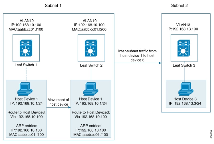
The following scenario shown in the figure below depicts a distributed gateway. Subnet 1 contains two leaf switches, leaf
switch 1 and leaf switch 2, acting together as a distributed default gateway for VLAN 10. Host device 1 is connected to leaf
switch 1, and needs to send traffic to host device 3, which is in a different subnet. When host device 1 tries to send traffic
outside of the subnet 1 through the configured gateway on leaf switch 1, it registers the Address Resolution Protocol (ARP)
entries of MAC and IP addresses of the gateway VLAN interface on leaf switch 1.
Figure 1. Distributed Gateway Topology
When multiple leaf switches act together as one single distributed default gateway for the same VLAN, the VLAN IP address
remains the same across all the leaf switches, and acts as the gateway IP address for a host that tries to reach an IP address
outside its subnet. But, each leaf switch retains its own MAC address.
In the above figure, if host device 1 moves from leaf switch 1 to leaf switch 2, while remaining within the same VXLAN network,
it still maintains the same ARP entries for gateway MAC and IP addresses. But, the MAC address of the VLAN interface on leaf
switch 2 is different from the MAC address of the VLAN interface on leaf switch 1. This results in a mismatch between the
MAC address in the ARP entry and the MAC address of the VLAN in leaf switch 2. As a result, the traffic from host device 1
that needs to be sent outside of Subnet 1 is either lost or gets continuously flooded as unknown unicast. EVPN VXLAN Distributed
anycast gateway feature prevents this from happening by ensuring that all the leaf switches have the same gateway MAC and
IP addresses.
There are two ways in which distributed anycast gateway can be configured in a VXLAN network to ensure that the MAC address
in the ARP entry of the host device matches with the MAC address across all leaf switches:
Manual MAC configuration
MAC aliasing
Manual MAC configuration
This is the conventional method of enabling distributed anycast gateway. With this method, you manually configure the same
MAC address on the same Layer 2 VNI VLAN's SVI on all the leaf switches in a VXLAN network.
Note
The VLAN SVIs on all the leaf switches must already share the same gateway IP address.
In Figure 1, to enable distibuted anycast gateway in subnet 1, the same MAC address must be configured on leaf switch 1 and leaf switch
2. This ensures that the ARP entries of gateway MAC and IP addresses on host device 1 match with the MAC and IP addresses
of both leaf switch 1 and leaf switch 2.
MAC Aliasing
MAC aliasing removes the need to explicitly configure the same MAC address on the VLAN interfaces of every leaf switch. MAC
aliasing allows the leaf switches in a VXLAN network to advertise the MAC addresses of their VLAN interface as the gateway
MAC addresses to all the other leaf switches in the network. The MAC address that is being advertised will be stored on each
leaf switch as a gateway MAC address, provided that the gateway IP address matches with the VLAN IP address.
In Figure 1, when MAC aliasing is enabled in subnet 1, leaf switch 1 and leaf switch 2 advertise their MAC addresses to each other as
gateway MAC addresses. As leaf switch 2 now recognizes the MAC address in the ARP entry of host device 1 as a gateway MAC
address, it sends the traffic from host device 1 outside of subnet 1, even though its MAC address does not match with the
ARP entry on host device 1.
MAC aliasing in a VXLAN network is configured by enabling the default gateway advertisement on all leaf switches.
Integrated Routing and Bridging
EVPN VXLAN supports Integrated Routing and Bridging (IRB) functionality which allows the VTEPs in a VXLAN network to forward
both Layer 2 (bridged) and Layer 3 (routed) traffic. When a VTEP forwards Layer 2 traffic, it is said to be performing bridging.
Similarly, when a VTEP forwards Layer 3 traffic, it is said to be performing routing. The traffic between different subnets
is forwarded through the VXLAN gateways. IRB is implemented in two ways:
Asymmetric IRB
Symmetric IRB
Asymmetric IRB
In asymmetric IRB, the ingress VTEP performs both bridging and routing while the egress VTEP performs only bridging. A packet
is forwarded through a MAC VRF followed by an IP VRF on the NVE of the ingress VTEP, and then forwarded only through MAC VRF
on the NVE of the egress VTEP. All the packet processing associated with inter-subnet forwarding semantics is confined to
the NVE of the ingress VTEP.
The return traffic during asymmetric IRB goes through a different VNI compared to the source traffic. This requires the source
and destination VNIs to be associated with both the ingress and egress VTEPs.
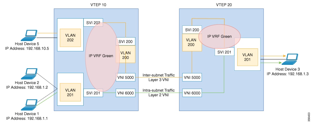
Symmetric IRB
In symmetric IRB, both the ingress and egress VTEPs perform both bridging and routing. A packet is forwarded through a MAC
VRF followed by an IP-VRF on the NVE of the ingress VTEP, and then forwarded through an IP VRF followed by a MAC VRF on the
NVE of the egress VTEP. All the packet processing associated with inter-subnet forwarding semantics is equally shared between
the NVEs of ingress and egress VTEPs.
Only the VNIs of locally attached endpoints need to be defined on the ingress and egress VTEPs when symmetric IRB is used.
This offers better scalability in terms of the number of VNIs that can be supported in a VXLAN fabric.
The following figure shows the implementation of symmetric IRB and the movement of traffic in an EVPN VXLAN network:
How to Configure EVPN VXLAN Integrated Routing and Bridging
To configure EVPN VXLAN IRB, you need to configure EVPN VXLAN Layer 2 and Layer 3 overlay networks, and enable the gateways
in the VXLAN network.
Configuring Core-facing and Access-facing VLANs on a VTEP
Perform this procedure to configure the core-facing and access-facing VLANs in order to enable IRB in the EVPN VXLAN network:
Procedure
Command or Action
Purpose
Step 1
enable
Example:
Device> enable
Enables privileged EXEC mode.
Enter your password, if prompted.
Step 2
configure terminal
Example:
Device# configure terminal
Enters global configuration mode.
Step 3
vlan configuration vlan-id
Example:
Device(config)# vlan configuration 201
Enters VLAN feature configuration mode for the specified VLAN interface.
Step 4
member evpn-instance evpn-instance-id vni l2-vni-number
Example:
Device(config-vlan)# member evpn-instance 1 vni 6000
Adds EVPN instance as a member of the VLAN configuration.
The VNI here is used as a Layer 2 VNI.
Step 5
exit
Example:
Device(config-vlan)# exit
Returns to global configuration mode.
Step 6
vlan configuration vlan-id
Example:
Device(config)# vlan configuration 202
Enters VLAN feature configuration mode for the specified VLAN interface.
Step 7
member evpn-instance evpn-instance-id vni l2-vni-number
Example:
Device(config-vlan)# member evpn-instance 2 vni 7000
Adds EVPN instance as a member of the VLAN configuration.
The VNI here is used as a Layer 2 VNI.
Step 8
exit
Example:
Device(config-vlan)# exit
Returns to global configuration mode.
Step 9
vlan configuration vlan-id
Example:
Device(config)# vlan configuration 200
Enters VLAN feature configuration mode for the specified VLAN interface.
Step 10
member vni l3-vni-number
Example:
Device(config-vlan)# member vni 5000
Adds EVPN instance as a member of the VLAN configuration.
The VNI here is used as a Layer 3 VNI.
Step 11
exit
Example:
Device(config-vlan)# exit
Returns to global configuration mode.
Step 12
end
Example:
Device(config-vlan)# end
Returns to privileged EXEC mode.
Configuring Switch Virtual Interface for the Core-facing VLAN
Perform this procedure to configure an SVI for the core-facing VLAN on the VTEP:
Procedure
Command or Action
Purpose
Step 1
enable
Example:
Device> enable
Enables privileged EXEC mode.
Enter your password, if prompted.
Step 2
configure terminal
Example:
Device# configure terminal
Enters global configuration mode.
Step 3
interface vlan vlan-id
Example:
Device(config)# interface vlan 200
Enters interface configuration mode for the specified VLAN.
Step 4
vrf forwarding vrf-name
Example:
Device(config-if)# vrf forwarding Green
Configures the SVI for the VLAN.
Step 5
ip unnumberedLoopback-interface
Example:
Device(config-if)# ip unnumbered Loopback0
Enables IP processing on the Loopback interface without assigning an explicit IP address to the interface.
Step 6
no autostate
Example:
Device(config-if)# no autostate
Disables autostate on the interface.
In EVPN deployments, once a VLAN is used for a core-facing SVI, it should not be allowed in any trunk. For a core-facing SVI
to function properly, the no autostate command must be configured under the SVI.
Step 7
end
Example:
Device(config-if)# end
Returns to privileged EXEC mode.
Configuring Switch Virtual Interface for the Access-facing VLANs
Perform this procedure to configure SVIs for the access-facing VLANs on the VTEP:
Procedure
Command or Action
Purpose
Step 1
enable
Example:
Device> enable
Enables privileged EXEC mode.
Enter your password, if prompted.
Step 2
configure terminal
Example:
Device# configure terminal
Enters global configuration mode.
Step 3
interface vlan vlan-id
Example:
Device(config)# interface vlan 202
Enters interface configuration mode for the specified VLAN.
Step 4
vrf forwarding vrf-name
Example:
Device(config-if)# vrf forwarding Green
Configures the SVI for the VLAN.
Step 5
ip address gateway-ip-address
Example:
Device(config-if)# ip address 192.168.10.1 255.255.255.0
Configures the gateway IP address for the access SVI.
Configure the same gateway IP address for this SVI on all the other VTEPs.
Step 6
mac-address mac-address-value
Example:
Device(config-if)# mac-address aabb.cc01.f100
(Optional) Manually sets the MAC address for the VLAN interface.
To configure distributed anycast gateway in a VXLAN network using manual MAC configuration, configure the same MAC address
on the corresponding Layer 2 VNI SVIs on all the VTEPs in a VXLAN network.
Perform this procedure to add Layer 2 and Layer 3 VNI members to the NVE interface of a VTEP:
Procedure
Command or Action
Purpose
Step 1
enable
Example:
Device> enable
Enables privileged EXEC mode.
Enter your password, if prompted.
Step 2
configure terminal
Example:
Device# configure terminal
Enters global configuration mode.
Step 3
interface nve-interface-id
Example:
Device(config)# interface nve1
Defines the interface to be configured as a trunk, and enters interface configuration mode.
Step 4
no ip address
Example:
Device(config-if)# no ip address
Disables IP processing on the interface by removing its IP address.
Step 5
source-interface loopback-interface-id
Example:
Device(config-if)# source-interface loopback0
Sets the IP address of the specified loopback interface as the source IP address.
Step 6
host-reachability protocol bgp
Example:
Device(config-if)# host-reachability protocol bgp
Configures BGP as the host-reachability protocol on the interface.
Step 7
member vni layer2-vni-id { ingress-replication | mcast-group multicast-group-address
Example:
Device(config-if)# member vni 6000 mcast-group 227.0.0.1
Device(config-if)# member vni 7000 mcast-group 227.0.0.1
Associates the Layer 2 VNI member with the NVE.
The specified replication type must match the replication type that is configured globally or for the specific EVPN instance.
Use mcast-group keyword for static replication and ingress-replication keyword for ingress replication.
Step 8
member vni layer3-vni-id vrf vrf-name
Example:
Device(config-if)# member vni 5000 vrf Green
Associates the Layer 3 VNI member with the NVE.
Step 9
end
Example:
Device(config-if)# end
Returns to privileged EXEC mode.
Configuring BGP with EVPN and VRF Address Families on a VTEP
To configure BGP on a VTEP with EVPN and VRF address families, and a spine switch as the neighbor, perform these steps:
Procedure
Command or Action
Purpose
Step 1
enable
Example:
Device> enable
Enables privileged EXEC mode.
Enter your password, if prompted.
Step 2
configure terminal
Example:
Device# configure terminal
Enters global configuration mode.
Step 3
router bgp autonomous-system-number
Example:
Device(config)# router bgp 1
Enables a BGP routing process, assigns it an autonomous system number, and enters router configuration mode.
Step 4
bgp log-neighbor-changes
Example:
Device(config-router)# bgp log-neighbor-changes
(Optional) Enables the generation of logging messages when the status of a BGP neighbor changes.
For more information, see Configuring BGP section of the IP Routing Configuration Guide.
Step 5
bgp update-delay time-period
Example:
Device(config-router)# bgp update-delay 1
(Optional) Sets the maximum initial delay period before sending the first update.
For more information, see Configuring BGP section of the IP Routing Configuration Guide.
Step 6
bgp graceful-restart
Example:
Device(config-router)# bgp graceful-restart
(Optional) Enables the BGP graceful restart capability for all BGP neighbors.
For more information, see Configuring BGP section of the IP Routing Configuration Guide.
Step 7
no bgp default ipv4-unicast
Example:
Device(config-router)# no bgp default ipv4-unicast
(Optional) Disables default IPv4 unicast address family for BGP peering session establishment.
For more information, see Configuring BGP section of the IP Routing Configuration Guide.
Enables the exchange information from a BGP neighbor.
Use the IP address of the spine switch as the neighbor IP address.
Step 12
neighbor ip-address send-community [ both | extended | standard]
Example:
Device(config-router-af)# neighbor 10.11.11.11 send-community both
Specifies the communities attribute sent to a BGP neighbor.
Use the IP address of the spine switch as the neighbor IP address.
Step 13
exit-address-family
Example:
Device(config-router-af)# exit-address-family
Exits address family configuration mode and returns to router configuration mode.
Step 14
address-family ipv4 vrf vrf-name
Example:
Device(config-router)# address-family ipv4 vrf green
Specifies the IPv4 address family and enters address family configuration mode.
Step 15
advertise l2vpn evpn
Example:
Device(config-router-af)# advertise l2vpn evpn
Advertises Layer 2 VPN EVPN routes within a tenant VRF in an EVPN VXLAN fabric.
Step 16
redistribute connected
Example:
Device(config-router-af)# redistribute connected
Redistributes connected routes to BGP.
Step 17
redistribute static
Example:
Device(config-router-af)# redistribute static
Redistributes static routes to BGP.
Step 18
exit-address-family
Example:
Device(config-router-af)# exit-address-family
Exits address family configuration mode and returns to router configuration mode.
Step 19
address-family ipv6 vrf vrf-name
Example:
Device(config-router)# address-family ipv6 vrf green
Specifies the IPv6 address family and enters address family configuration mode.
Step 20
advertise l2vpn evpn
Example:
Device(config-router-af)# advertise l2vpn evpn
Advertises Layer 2 VPN EVPN routes within a tenant VRF in an EVPN VXLAN fabric.
Step 21
redistribute connected
Example:
Device(config-router-af)# redistribute connected
Redistributes connected routes to BGP.
Step 22
redistribute static
Example:
Device(config-router-af)# redistribute static
Redistributes static routes to BGP.
Step 23
exit-address-family
Example:
Device(config-router-af)# exit-address-family
Exits address family configuration mode and returns to router configuration mode.
Step 24
end
Example:
Device(config-router)# end
Returns to privileged EXEC mode.
Configuration Examples for EVPN VXLAN Anycast Gateway
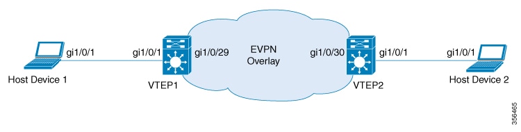
This section provides an example for enabled EVPN VXLAN IRB using distributed anycast gateway. The following example shows
a sample configuration for a VXLAN network with 2 VTEPs, VTEP 1 and VTEP 2, connected to perform integrated routing and bridging.
Table 1. Configuration Example for a VXLAN Network with Two VTEPs Connected to Perform Integrated Routing and Bridging Using Distributed
Anycast Gateway
VTEP 1
VTEP 2
VTEP1# show running-config
!
hostname VTEP1
!
vrf definition green
 rd 103:2
 !
 address-family ipv4
  route-target export 103:2
  route-target import 104:2
  route-target export 103:2 stitching
  route-target import 104:2 stitching
 exit-address-family
 !
 address-family ipv6
  route-target export 103:2
  route-target import 104:2
  route-target export 103:2 stitching
  route-target import 104:2 stitching
 exit-address-family
!
ip routing
ip multicast-routing
ipv6 unicast-routing
!
!
l2vpn evpn
 replication-type static
 router-id Loopback0
 default-gateway advertise
!
l2vpn evpn instance 1 vlan-based
 encapsulation vxlan
!
l2vpn evpn instance 2 vlan-based
 encapsulation vxlan
!
!
system mtu 9150
!
vlan configuration 200
 member vni 5000
vlan configuration 201
 member evpn-instance 1 vni 6000
vlan configuration 202
 member evpn-instance 2 vni 7000
!
!
interface Loopback0
 ip address 10.1.1.10 255.255.255.255
 ip pim sparse-mode
!
interface Loopback13
description demo only (for rt5 distribution)
 vrf forwarding green
 ip address 10.1.13.13 255.255.255.0
!
interface GigabitEthernet1/0/1
description access-facing-interface
 switchport trunk allowed vlan 201,202
 switchport mode trunk
!
!
interface GigabitEthernet1/0/29
 description core-underlay-interface
 no switchport
 ip address 172.16.1.29 255.255.255.0
 ip pim sparse-mode
!
!
interface Vlan200
 description core svi for l3vni
 vrf forwarding green
 ip unnumbered Loopback0
 ipv6 enable
 no autostate
!
interface Vlan201
 description vni 6000 default-gateway
 vrf forwarding green
 ip address 192.168.1.201 255.255.255.0
 ipv6 address 2001:DB8:201::201/64
 ipv6 enable
!
interface Vlan202
 description vni 7000 default-gateway
 vrf forwarding green
 ip address 192.168.2.202 255.255.255.0
 ipv6 address 2001:DB8:202::202/64
 ipv6 enable
!
!
interface nve10
 no ip address
 source-interface Loopback0
 host-reachability protocol bgp
 member vni 6000 mcast-group 232.1.1.1
 member vni 5000 vrf green
 member vni 7000 mcast-group 232.1.1.1
!
router ospf 1
 router-id 10.1.1.10
 network 10.1.1.0 0.0.0.255 area 0
 network 172.16.1.0 0.0.0.255 area 0
!
router bgp 10
 bgp router-id interface Loopback0
 bgp log-neighbor-changes
 bgp update-delay 1
 no bgp default ipv4-unicast
 neighbor 10.2.2.20 remote-as 10
 neighbor 10.2.2.20 update-source Loopback0
 !
 address-family ipv4
 exit-address-family
 !
 address-family l2vpn evpn
  neighbor 10.2.2.20 activate
  neighbor 10.2.2.20 send-community both
 exit-address-family
 !
 address-family ipv4 vrf green
  advertise l2vpn evpn
  redistribute connected
  redistribute static
 exit-address-family
 !
 address-family ipv6 vrf green
  redistribute connected
  redistribute static
  advertise l2vpn evpn
 exit-address-family
!
ip pim rp-address 10.1.1.10
!
end
VTEP2# show running-config
!
hostname VTEP2
!
vrf definition green
 rd 104:2
 !
 address-family ipv4
  route-target export 104:2
  route-target import 103:2
  route-target export 104:2 stitching
  route-target import 103:2 stitching
 exit-address-family
 !
 address-family ipv6
  route-target export 104:2
  route-target import 103:2
  route-target export 104:2 stitching
  route-target import 103:2 stitching
 exit-address-family
!
ip routing
ip multicast-routing
ipv6 unicast-routing
!
!
l2vpn evpn
 replication-type static
 router-id Loopback0
 default-gateway advertise
!
l2vpn evpn instance 1 vlan-based
 encapsulation vxlan
!
l2vpn evpn instance 2 vlan-based
 encapsulation vxlan
!
!
system mtu 9150
!
vlan configuration 200
 member vni 5000
vlan configuration 201
 member evpn-instance 1 vni 6000
vlan configuration 202
 member evpn-instance 2 vni 7000
!
!
interface Loopback0
 ip address 10.2.2.20 255.255.255.255
 ip pim sparse-mode
!
interface Loopback14
 description demo only (for rt5 distribution)
 vrf forwarding green
 ip address 10.1.14.14 255.255.255.0
!
interface GigabitEthernet1/0/1
description access-facing-interface
 switchport trunk allowed vlan 201,202
 switchport mode trunk
!
!
interface GigabitEthernet1/0/30
 description core-underlay-interface
 no switchport
 ip address 172.16.1.30 255.255.255.0
 ip pim sparse-mode
!
!
interface Vlan200
 description core svi for l3vni
 vrf forwarding green
 ip unnumbered Loopback0
 ipv6 enable
 no autostate
!
interface Vlan201
 description vni 6000 default-gateway
 vrf forwarding green
 ip address 192.168.1.201 255.255.255.0
 ipv6 address 2001:DB8:201::201/64
 ipv6 enable
!
interface Vlan202
 description vni 7000 default-gateway
 vrf forwarding green
 ip address 192.168.2.202 255.255.255.0
 ipv6 address 2001:DB8:202::202/64
 ipv6 enable
!
!
interface nve10
 no ip address
 source-interface Loopback0
 host-reachability protocol bgp
 member vni 6000 mcast-group 232.1.1.1
 member vni 7000 mcast-group 232.1.1.1
 member vni 5000 vrf green
!
router ospf 1
 router-id 10.2.2.20
 network 10.2.2.0 0.0.0.255 area 0
 network 172.16.1.0 0.0.0.255 area 0
!
router bgp 10
 bgp router-id interface Loopback0
 bgp log-neighbor-changes
 bgp update-delay 1
 no bgp default ipv4-unicast
 neighbor 10.1.1.10 remote-as 10
 neighbor 10.1.1.10 update-source Loopback0
 !
 address-family ipv4
 exit-address-family
 !
 address-family l2vpn evpn
  neighbor 10.1.1.10 activate
  neighbor 10.1.1.10 send-community both
 exit-address-family
 !
 address-family ipv4 vrf green
  advertise l2vpn evpn
  redistribute connected
  redistribute static
 exit-address-family
 !
 address-family ipv6 vrf green
  redistribute connected
  redistribute static
  advertise l2vpn evpn
 exit-address-family
!
ip pim rp-address 10.1.1.10
!
end
The following examples provide outputs for show commands on VTEP 1 and VTEP 2 in the topology configured above.
The following example shows the output for the show ip route vrf vrf-name command on VTEP 1:
VTEP1# show ip route vrf green
Routing Table: green
Codes: L - local, C - connected, S - static, R - RIP, M - mobile, B - BGP
       D - EIGRP, EX - EIGRP external, O - OSPF, IA - OSPF inter area
       N1 - OSPF NSSA external type 1, N2 - OSPF NSSA external type 2
       E1 - OSPF external type 1, E2 - OSPF external type 2, m - OMP
       n - NAT, Ni - NAT inside, No - NAT outside, Nd - NAT DIA
       i - IS-IS, su - IS-IS summary, L1 - IS-IS level-1, L2 - IS-IS level-2
       ia - IS-IS inter area, * - candidate default, U - per-user static route
       H - NHRP, G - NHRP registered, g - NHRP registration summary
       o - ODR, P - periodic downloaded static route, l - LISP
       a - application route
       + - replicated route, % - next hop override, p - overrides from PfR

Gateway of last resort is not set

      10.0.0.0/8 is variably subnetted, 3 subnets, 2 masks
C        10.1.13.0/24 is directly connected, Loopback13
L        10.1.13.13/32 is directly connected, Loopback13
B        10.1.14.0/24 [200/0] via 10.2.2.20, 01:30:02, Vlan200
      192.168.1.0/24 is variably subnetted, 3 subnets, 2 masks
C        192.168.1.0/24 is directly connected, Vlan201
B        192.168.1.89/32 [200/0] via 10.2.2.20, 00:04:05, Vlan200
L        192.168.1.201/32 is directly connected, Vlan201
      192.168.2.0/24 is variably subnetted, 3 subnets, 2 masks
C        192.168.2.0/24 is directly connected, Vlan202
B        192.168.2.89/32 [200/0] via 10.2.2.20, 00:04:10, Vlan200
L        192.168.2.202/32 is directly connected, Vlan202
VTEP 2
The following example shows the output for the show ip route vrf vrf-name command on VTEP 2:
VTEP2# show ip route vrf green
Routing Table: green
Codes: L - local, C - connected, S - static, R - RIP, M - mobile, B - BGP
       D - EIGRP, EX - EIGRP external, O - OSPF, IA - OSPF inter area
       N1 - OSPF NSSA external type 1, N2 - OSPF NSSA external type 2
       E1 - OSPF external type 1, E2 - OSPF external type 2, m - OMP
       n - NAT, Ni - NAT inside, No - NAT outside, Nd - NAT DIA
       i - IS-IS, su - IS-IS summary, L1 - IS-IS level-1, L2 - IS-IS level-2
       ia - IS-IS inter area, * - candidate default, U - per-user static route
       H - NHRP, G - NHRP registered, g - NHRP registration summary
       o - ODR, P - periodic downloaded static route, l - LISP
       a - application route
       + - replicated route, % - next hop override, p - overrides from PfR

Gateway of last resort is not set

      10.0.0.0/8 is variably subnetted, 3 subnets, 2 masks
B        10.1.13.0/24 [200/0] via 10.1.1.10, 01:31:17, Vlan200
C        10.1.14.0/24 is directly connected, Loopback14
L        10.1.14.14/32 is directly connected, Loopback14
      192.168.1.0/24 is variably subnetted, 3 subnets, 2 masks
C        192.168.1.0/24 is directly connected, Vlan201
B        192.168.1.81/32 [200/0] via 10.1.1.10, 01:39:53, Vlan200
L        192.168.1.201/32 is directly connected, Vlan201
      192.168.2.0/24 is variably subnetted, 3 subnets, 2 masks
C        192.168.2.0/24 is directly connected, Vlan202
B        192.168.2.81/32 [200/0] via 10.1.1.10, 01:39:30, Vlan200
L        192.168.2.202/32 is directly connected, Vlan202
show platform software fed switch active matm mactable vlan
VTEP 1
The following examples show the output for the show platform software fed switch active matm mactable vlan vlan-id command on VTEP 1:
Note
The MAC address of the peer's core SVI interface must be present in the core VLAN.

 Feedback