Configuring Optional Spanning-Tree Features
Information About Optional Spanning-Tree Features
The following sections provide information about Optional Spanning-Tree features:
PortFast
PortFast immediately brings an interface configured as an access or trunk port to the forwarding state from a blocking state, bypassing the listening and learning states.
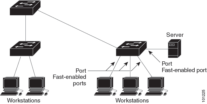
Interfaces connected to a single workstation or server should not receive bridge protocol data units (BPDUs). An interface with PortFast enabled goes through the normal cycle of spanning-tree status changes when the switch is restarted.
You can enable this feature by enabling it on either the interface or on all nontrunking ports.
 Note |
PortFast edge feature is supported only on C9500-32C, C9500-32QC, C9500-48Y4C, and C9500-24Y4C models of the Cisco Catalyst 9500 Series Switches |
Spanning Tree Protocol PortFast Port Types
You can configure a spanning tree port (STP) as an edge port, a network port, or a normal port. A port can be in only one of these states at a given time. The default spanning tree port type is normal. You can configure the port type either globally or per interface.
Note |
Configuring an STP PortFast port type is supported only on the Cisco Catalyst High Performance Series switches (C9500-32C, C9500-32QC, C9500-48Y4C, and C9500-24Y4C models). |
Depending on the type of device to which the interface is connected, you can configure a spanning tree port as one of these port types:
-
A PortFast edge port: It is connected to a Layer 2 host. This can be either an access port or an edge trunk port (portfast edge trunk). This type of port interface immediately transitions to the forwarding state, bypassing the listening and learning states. Use PortFast edge on Layer 2 access ports connected to a single workstation or server to allow those devices to connect to the network immediately, rather than waiting for spanning tree to converge.
Even if the interface receives a bridge protocol data unit (BPDU), spanning tree does not place the port into the blocking state. Spanning tree sets the operating state of the port to nonport fast even if the configured state remains port fast edge and starts participating in the topology change.
Note
If you configure a port connected to a Layer 2 switch or bridge as an edge port, you might create a bridging loop.
-
A PortFast network port: It is connected only to a Layer 2 switch or bridge.
Bridge Assurance is enabled only on PortFast network ports. For more information, see Bridge Assurance.
Note
If you configure a port that is connected to a Layer 2 host as a spanning tree network port, the port automatically moves into the blocking state.
-
A PortFast normal port: It is the default type of spanning tree port.
Note
If you enter the spanning-tree portfast trunk command in the global or interface configuration mode, the system automatically saves it as spanning-tree portfast edge trunk .
Bridge Protocol Data Unit Guard
The Bridge Protocol Data Unit (BPDU) guard feature can be globally enabled on the switch or can be enabled per port, but the feature operates with some differences.
When you enable BPDU guard at the global level on PortFast edge-enabled ports or PortFast enabled ports, spanning tree shuts down ports that are in a PortFast edge-operational or PortFast operational state if any BPDU is received on them. In a valid configuration, PortFast edge-enabled ports or PortFast enabled ports do not receive BPDUs. Receiving a BPDU on a PortFast edge-enabled port or PortFast enabled port means an invalid configuration, such as the connection of an unauthorized device, and the BPDU guard feature puts the port in the error-disabled state. When this happens, the switch shuts down the entire port on which the violation occurred.
When you enable BPDU guard at the interface level on any port without also enabling the PortFast edge feature or PortFast feature, and the port receives a BPDU, it is put in the error-disabled state.
The BPDU guard feature provides a secure response to invalid configurations because you must manually put the interface back in service. Use the BPDU guard feature in a service-provider network to prevent an access port from participating in the spanning tree.
Bridge Protocol Data Unit Filtering
The BPDU filtering feature can be globally enabled on the switch or can be enabled per interface, but the feature operates with some differences.
Enabling BPDU filtering on PortFast edge-enabled interfaces or PortFast enabled interfaces at the global level keeps those interfaces that are in a PortFast edge-operational or PortFast operational state from sending or receiving BPDUs. The interfaces still send a few BPDUs at link-up before the switch begins to filter outbound BPDUs. You should globally enable BPDU filtering on a switch so that hosts that are connected to these interfaces do not receive BPDUs. If a BPDU is received on a PortFast edge-enabled interface or PortFast enabled interface, the interface loses its PortFast edge-operational status or PortFast operational status, and BPDU filtering is disabled.
Enabling BPDU filtering on an interface without also enabling the PortFast edge feature or PortFast feature keeps the interface from sending or receiving BPDUs.
 Caution |
Enabling BPDU filtering on an interface is the same as disabling spanning tree on it and can result in spanning-tree loops. |
You can enable the BPDU filtering feature for the entire switch or for an interface.
Bridge Assurance
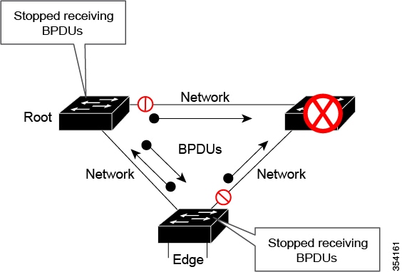
You can use Bridge Assurance to help prevent looping conditions that are caused by unidirectional links (one-way traffic on a link or port), or a malfunction in a neighboring switch. Here, a malfunction refers to a switch that is not able to run STP any more, while still forwarding traffic (a brain dead switch).
BPDUs are sent out on all operational network ports, including alternate and backup ports, for each hello time period. Bridge Assurance monitors the receipt of BPDUs on point-to-point links on all network ports. When a port does not receive BPDUs within the alloted hello time period, the port is put into a blocked state (the same as a port inconsistent state, which stops forwarding of frames). When the port resumes receipt of BPDUs, the port resumes normal spanning tree operations.
Note |
Only Rapid PVST+ and MST spanning tree protocols support Bridge Assurance. PVST+ does not support Bridge Assurance. Bridge Assurance is supported only on the Cisco Catalyst High Performanace Series switches (C9500-32C, C9500-32QC, C9500-48Y4C, and C9500-24Y4C models). |
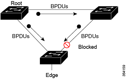
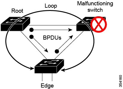
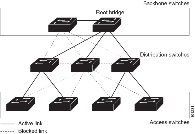
The following example shows how Bridge Assurance protects your network from bridging loops. Here, Network with Normal STP Topology shows a normal STP topology, and Network Loop Due to a Malfunctioning Switch demonstrates a potential network problem when the device fails (brain dead) and Bridge Assurance is not enabled on the network.
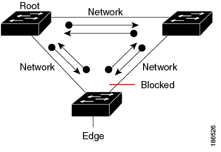
Network with STP Topology Running Bridge Assurance shows the network with Bridge Assurance enabled, and the STP topology progressing normally with bidirectional BDPUs issuing from every STP network port. Network Problem Averted with Bridge Assurance Enabled shows how the potential network problem shown in Network Loop Due to a Malfunctioning Switch does not occur when you have Bridge Assurance enabled on your network.
The system generates syslog messages when a port is blocked or unblocked. The following sample outputs show the log that is generated for each of these states:
Blocked port:
Sep 17 09:48:16.249 PDT: %SPANTREE-2-BRIDGE_ASSURANCE_BLOCK: Bridge
Assurance blocking port GigabitEthernet5/8 on VLAN0200. (stack-dut-R4-4)
Unblocked Port:
Sep 17 09:48:58.426 PDT: %SPANTREE-2-BRIDGE_ASSURANCE_UNBLOCK:
Bridge Assurance unblocking port GigabitEthernet5/8 on VLAN0200. (stack-dut-R4-4)
Guidelines for Configuring Bridge Assurance
Observe these guidelines when configuring Bridge Assurance:
-
Bridge Assurance can be enabled or disabled globally.
-
Bridge Assurance applies to all operational network ports, including alternate and backup ports.
-
Only Rapid PVST+ and MST spanning tree protocols support Bridge Assurance. PVST+ does not support Bridge Assurance.
-
For Bridge Assurance to work properly, it must be supported and configured on both ends of a point-to-point link. If the device on one side of the link has Bridge Assurance enabled and the device on the other side does not, then the connecting port is blocked (a Bridge Assurance inconsistent state). We recommend that you enable Bridge Assurance throughout your network.
-
To enable Bridge Assurance on a port, BPDU filtering and BPDU Guard must be disabled.
-
You can enable Bridge Assurance along with Loop Guard.
-
You can enable Bridge Assurance along with Root Guard. The latter is designed to provide a way to enforce the root bridge placement in the network.
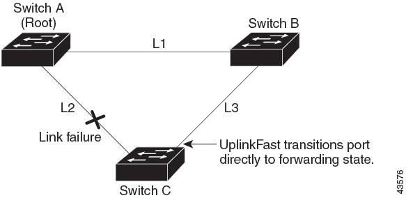
UplinkFast
If a switch loses connectivity, it begins using the alternate paths when the spanning tree selects a new root port. You can accelerate the choice of a new root port when a link or switch fails or when the spanning tree reconfigures itself by enabling UplinkFast. The root port transitions to the forwarding state immediately without going through the listening and learning states, as it would with the normal spanning-tree procedures.
When the spanning tree reconfigures the new root port, other interfaces flood the network with multicast packets, one for each address that was learned on the interface. You can limit these bursts of multicast traffic by reducing the max-update-rate parameter (the default for this parameter is 150 packets per second). However, if you enter zero, station-learning frames are not generated, so the spanning-tree topology converges more slowly after a loss of connectivity.
Note |
UplinkFast is most useful in wiring-closet switches at the access or edge of the network. It is not appropriate for backbone devices. This feature might not be useful for other types of applications. |
UplinkFast provides fast convergence after a direct link failure and achieves load-balancing between redundant Layer 2 links using uplink groups. An uplink group is a set of Layer 2 interfaces (per VLAN), only one of which is forwarding at any given time. Specifically, an uplink group consists of the root port (which is forwarding) and a set of blocked ports, except for self-looping ports. The uplink group provides an alternate path in case the currently forwarding link fails.
Cross-Stack UplinkFast
Cross-Stack UplinkFast (CSUF) provides a fast spanning-tree transition (fast convergence in less than 1 second under normal network conditions) across a switch stack. During the fast transition, an alternate redundant link on the switch stack is placed in the forwarding state without causing temporary spanning-tree loops or loss of connectivity to the backbone. With this feature, you can have a redundant and resilient network in some configurations. CSUF is automatically enabled when you enable the UplinkFast feature.
CSUF might not provide a fast transition all the time; in these cases, the normal spanning-tree transition occurs, completing in 30 to 40 seconds. For more information, see Related Topics.
How Cross-Stack UplinkFast Works
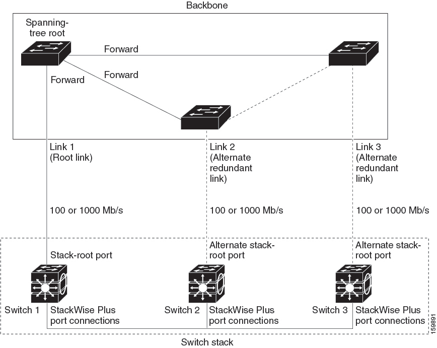
Cross-Stack UplinkFast (CSUF) ensures that one link in the stack is elected as the path to the root.
The stack-root port on Switch 1 provides the path to the root of the spanning tree. The alternate stack-root ports on Switches 2 and 3 can provide an alternate path to the spanning-tree root if the current stack-root switch fails or if its link to the spanning-tree root fails.
Link 1, the root link, is in the spanning-tree forwarding state. Links 2 and 3 are alternate redundant links that are in the spanning-tree blocking state. If Switch 1 fails, if its stack-root port fails, or if Link 1 fails, CSUF selects either the alternate stack-root port on Switch 2 or Switch 3 and puts it into the forwarding state in less than 1 second.
When certain link loss or spanning-tree events occur (described in the following topic), the Fast Uplink Transition Protocol uses the neighbor list to send fast-transition requests to stack members.
The switch sending the fast-transition request needs to do a fast transition to the forwarding state of a port that it has chosen as the root port, and it must obtain an acknowledgment from each stack switch before performing the fast transition.
Each switch in the stack decides if the sending switch is a better choice than itself to be the stack root of this spanning-tree instance by comparing the root, cost, and bridge ID. If the sending switch is the best choice as the stack root, each switch in the stack returns an acknowledgment; otherwise, it sends a fast-transition request. The sending switch then has not received acknowledgments from all stack switches.
When acknowledgments are received from all stack switches, the Fast Uplink Transition Protocol on the sending switch immediately transitions its alternate stack-root port to the forwarding state. If acknowledgments from all stack switches are not obtained by the sending switch, the normal spanning-tree transitions (blocking, listening, learning, and forwarding) take place, and the spanning-tree topology converges at its normal rate (2 * forward-delay time + max-age time).
The Fast Uplink Transition Protocol is implemented on a per-VLAN basis and affects only one spanning-tree instance at a time.
Events That Cause Fast Convergence
Depending on the network event or failure, the CSUF fast convergence might or might not occur.
Fast convergence (less than 1 second under normal network conditions) occurs under these circumstances:
-
The stack-root port link fails.
If two switches in the stack have alternate paths to the root, only one of the switches performs the fast transition.
-
The failed link, which connects the stack root to the spanning-tree root, recovers.
-
A network reconfiguration causes a new stack-root switch to be selected.
-
A network reconfiguration causes a new port on the current stack-root switch to be chosen as the stack-root port.
Note
The fast transition might not occur if multiple events occur simultaneously. For example, if a stack member is powered off, and at the same time, the link connecting the stack root to the spanning-tree root comes back up, the normal spanning-tree convergence occurs.
Normal spanning-tree convergence (30 to 40 seconds) occurs under these conditions:
-
The stack-root switch is powered off, or the software failed.
-
The stack-root switch, which was powered off or failed, is powered on.
-
A new switch, which might become the stack root, is added to the stack.
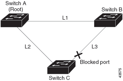
BackboneFast
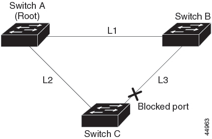
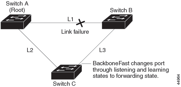
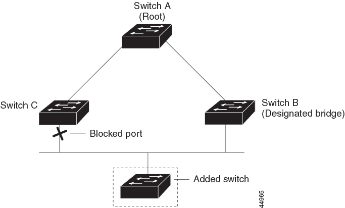
BackboneFast detects indirect failures in the core of the backbone. BackboneFast is a complementary technology to the UplinkFast feature, which responds to failures on links that are directly connected to access switches. BackboneFast optimizes the maximum-age timer, which controls the amount of time the switch stores protocol information that is received on an interface. When a switch receives an inferior BPDU from the designated port of another switch, the BPDU is a signal that the other switch might have lost its path to the root, and BackboneFast tries to find an alternate path to the root.
BackboneFast starts when a root port or blocked interface on a switch receives inferior BPDUs from its designated switch. An inferior BPDU identifies a switch that declares itself as both the root bridge and the designated switch. When a switch receives an inferior BPDU, it means that a link to which the switch is not directly connected (an indirect link) has failed (that is, the designated switch has lost its connection to the root switch). Under spanning-tree rules, the switch ignores inferior BPDUs for the maximum aging time (default is 20 seconds).
The switch tries to find if it has an alternate path to the root switch. If the inferior BPDU arrives on a blocked interface, the root port and other blocked interfaces on the switch become alternate paths to the root switch. (Self-looped ports are not considered alternate paths to the root switch.) If the inferior BPDU arrives on the root port, all blocked interfaces become alternate paths to the root switch. If the inferior BPDU arrives on the root port and there are no blocked interfaces, the switch assumes that it has lost connectivity to the root switch, causes the maximum aging time on the root port to expire, and becomes the root switch according to normal spanning-tree rules.
If the switch has alternate paths to the root switch, it uses these alternate paths to send a root link query (RLQ) request. The switch sends the RLQ request on all alternate paths to learn if any stack member has an alternate root to the root switch and waits for an RLQ reply from other switches in the network and in the stack. The switch sends the RLQ request on all alternate paths and waits for an RLQ reply from other switches in the network.
When a stack member receives an RLQ reply from a nonstack member on a blocked interface and the reply is destined for another nonstacked switch, it forwards the reply packet, regardless of the spanning-tree interface state.
When a stack member receives an RLQ reply from a nonstack member and the response is destined for the stack, the stack member forwards the reply so that all the other stack members receive it.
If the switch discovers that it still has an alternate path to the root, it expires the maximum aging time on the interface that received the inferior BPDU. If all the alternate paths to the root switch indicate that the switch has lost connectivity to the root switch, the switch expires the maximum aging time on the interface that received the RLQ reply. If one or more alternate paths can still connect to the root switch, the switch makes all interfaces on which it received an inferior BPDU its designated ports and moves them from the blocking state (if they were in the blocking state), through the listening and learning states, and into the forwarding state.
EtherChannel Guard
You can use EtherChannel guard to detect an EtherChannel misconfiguration between the switch and a connected device. A misconfiguration can occur if the switch interfaces are configured in an EtherChannel, but the interfaces on the other device are not. A misconfiguration can also occur if the channel parameters are not the same at both ends of the EtherChannel.
If the switch detects a misconfiguration on the other device, EtherChannel guard places the switch interfaces in the error-disabled state, and displays an error message.
Root Guard
The Layer 2 network of a service provider (SP) can include many connections to switches that are not owned by the SP. In such a topology, the spanning tree can reconfigure itself and select a customer switch as the root switch. You can avoid this situation by enabling root guard on SP switch interfaces that connect to switches in your customer’s network. If spanning-tree calculations cause an interface in the customer network to be selected as the root port, root guard then places the interface in the root-inconsistent (blocked) state to prevent the customer’s switch from becoming the root switch or being in the path to the root.
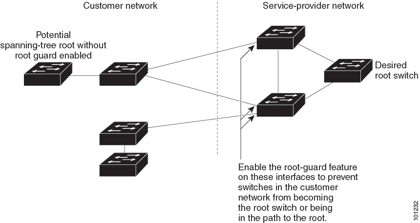
If a switch outside the SP network becomes the root switch, the interface is blocked (root-inconsistent state), and spanning tree selects a new root switch. The customer’s switch does not become the root switch and is not in the path to the root.
If the switch is operating in MST mode, root guard forces the interface to be a designated port. If a boundary port is blocked in an internal spanning-tree (IST) instance because of root guard, the interface also is blocked in all MST instances. A boundary port is an interface that connects to a LAN, the designated switch of which is either an IEEE 802.1D switch or a switch with a different MST region configuration.
Root guard that is enabled on an interface applies to all the VLANs to which the interface belongs. VLANs can be grouped and mapped to an MST instance.
Caution |
Misuse of the root guard feature can cause a loss of connectivity. |
Loop Guard
You can use loop guard to prevent alternate or root ports from becoming designated ports because of a failure that leads to a unidirectional link. This feature is most effective when it is enabled on the entire switched network. Loop guard prevents alternate and root ports from becoming designated ports, and spanning tree does not send BPDUs on root or alternate ports.
When the switch is operating in PVST+ or rapid-PVST+ mode, loop guard prevents alternate and root ports from becoming designated ports, and spanning tree does not send BPDUs on root or alternate ports.
When the switch is operating in MST mode, BPDUs are not sent on nonboundary ports only if the interface is blocked by loop guard in all MST instances. On a boundary port, loop guard blocks the interface in all MST instances.
How to Configure Optional Spanning-Tree Features
The following sections provide information about configuring Optional Spanning-Tree features:
(Optional) Enabling PortFast
An interface with the PortFast feature enabled is moved directly to the spanning-tree forwarding state without waiting for the standard forward-time delay.
If you enable the voice VLAN feature, the PortFast feature is automatically enabled. When you disable voice VLAN, the PortFast feature is not automatically disabled.
You can enable this feature if your switch is running PVST+, Rapid PVST+, or MSTP.
Caution |
Use PortFast only when connecting a single end station to an access or trunk port. Enabling this feature on an interface that is connected to a switch or hub could prevent spanning tree from detecting and disabling loops in your network, which could cause broadcast storms and address-learning problems. |
To enable PortFast, perform this procedure:
Procedure
| Command or Action | Purpose | |||
|---|---|---|---|---|
|
Step 1 |
enable Example: |
Enables privileged EXEC mode. Enter your password if prompted. |
||
|
Step 2 |
configure terminal Example: |
Enters global configuration mode. |
||
|
Step 3 |
interface interface-id Example: |
Specifies an interface to configure, and enters interface configuration mode. |
||
|
Step 4 |
spanning-tree portfast [trunk] Example: |
Enables PortFast on an access port that is connected to a single workstation or server. By specifying the trunk keyword, you can enable PortFast on a trunk port.
By default, PortFast is disabled on all interfaces. |
||
|
Step 5 |
end Example: |
Returns to privileged EXEC mode. |
What to do next
You can use the spanning-tree portfast default global configuration command to globally enable the PortFast feature on all nontrunking ports.
Enabling PortFast Port Types
The following sections provide configurational information about enabling PortFast port types:
Configuring the PortFast Default State Globally
To configure the default PortFast state, perform this task:
Procedure
| Command or Action | Purpose | |
|---|---|---|
|
Step 1 |
configure terminal Example: |
Enters global configuration mode. |
|
Step 2 |
spanning-tree portfast [ edge | network | normal] default Example: |
Configures the default state for all interfaces on the switch. You have these options:
|
|
Step 3 |
end Example: |
Exits configuration mode. |
Configuring a PortFast Edge Port on a Specified Interface
Interfaces configured as edge ports immediately transition to the forwarding state, without passing through the blocking or learning states, on linkup. To configure an edge port on a specified interface, perform this task:
Note |
Because the purpose of this type of port is to minimize the time that access ports must wait for spanning tree to converge, it is most effective when used on access ports. If you enable PortFast edge on a port connecting to another switch, you risk creating a spanning tree loop. |
To configure a PortFast edge port on a specified interface, perform this procedure:
Procedure
| Command or Action | Purpose | |
|---|---|---|
|
Step 1 |
configure terminal Example: |
Enters global configuration mode. |
|
Step 2 |
interface {{ fastethernet | gigabitethernet | tengigabitethernet } slot / port } | { port-channel port_channel_number} Example: |
Enables edge behavior on a Layer 2 access port connected to an end workstation or server. (Optional) trunk: Enables edge behavior on a trunk port. Use this keyword if the link is a trunk. Use this command only on ports that are connected to end host devices that terminate VLANs and from which the port should never receive STP BPDUs. Such end host devices include workstations, servers, and ports on routers that are not configured to support bridging. Use the no version of the command to disable PortFast edge. |
|
Step 3 |
end Example: |
Exits configuration mode. |
|
Step 4 |
show spanning-tree interface {{ fastethernet | gigabitethernet | tengigabitethernet } slot / port } | { port-channel port_channel_number} portfast edge Example: |
Displays spanning-tree PortFast information for the specified interface. |
Example
This example shows how to enable edge behavior on GigabitEthernet interface 5/7 and verify the configuration:
Device# configure terminal
Device(config)# interface fastethernet 5/7
Device(config-if)# spanning-tree portfast edge
Device(config-if)# end
Device#

Device# show running-config interface fastethernet 5/7
Building configuration...
Current configuration:
!
interface GigabitEthernet5/7
no ip address
switchport
switchport access vlan 200
switchport mode access
spanning-tree portfast edge
end
This example shows how you can display that port GigabitEthernet 5/8 is currently in the edge state:
Device# show spanning-tree vlan 200
VLAN0200
Spanning tree enabled protocol rstp
Root ID Priority 2
Address 001b.2a68.5fc0
Cost 3
Port 125 (GigabitEthernet5/9)
Hello Time 2 sec Max Age 20 sec Forward Delay 15 sec

Bridge ID Priority 2 (priority 0 sys-id-ext 2)
Address 7010.5c9c.5200
Hello Time 2 sec Max Age 20 sec Forward Delay 15 sec
Aging Time 0 sec

Interface Role Sts Cost Prio.Nbr Type
------------------- ---- --- --------- -------- --------------------------------
Gi5/7 Desg FWD 4 128.1 P2p EdgeConfiguring a PortFast Network Port on a Specified Interface
Ports that are connected to Layer 2 switches and bridges can be configured as network ports.
Note |
Bridge Assurance is enabled only on PortFast network ports. For more information, see Bridge Assurance. |
To configure a port as a network port, perform this task:
Procedure
| Command or Action | Purpose | |
|---|---|---|
|
Step 1 |
configure terminal Example: |
Enters global configuration mode. |
|
Step 2 |
interface {{ fastethernet | gigabitethernet | tengigabitethernet } slot / port } | { port-channel port_channel_number} Example: |
Configures the port as a network port. If you have enabled Bridge Assurance globally, it automatically runs on a spanning tree network port. Use the no keyword to disable PortFast. |
|
Step 3 |
end Example: |
Exits configuration mode. |
|
Step 4 |
show running interface {{ fastethernet | gigabitethernet | tengigabitethernet } slot / port } | { port-channel port_channel_number} Example: |
Verifies the configuration. |
Example
This example shows how to configure GigabitEthernet interface 5/8 as a network port and verify configuration:
Device# configure terminal
Device(config)# interface gigabitethernet 5/8
Device(config-if)# spanning-tree portfast network
Device(config-if)# end
Device#

Device# show running-config interface gigabitethernet 5/8
Building configuration...
Current configuration:
!
interface GigabitEthernet5/8
no ip address
switchport
switchport access vlan 200
switchport mode access
spanning-tree portfast network
endEnabling BPDU Guard
You can enable the BPDU guard feature if your switch is running PVST+, Rapid PVST+, or MSTP.
Caution |
Configure PortFast edge or PortFast only on ports that connect to end stations; otherwise, an accidental topology loop could cause a data packet loop and disrupt switch and network operation. |
This procedure is optional.
Procedure
| Command or Action | Purpose | |
|---|---|---|
|
Step 1 |
enable Example: |
Enables privileged EXEC mode. Enter your password if prompted. |
|
Step 2 |
configure terminal Example: |
Enters global configuration mode. |
|
Step 3 |
interface interface-id Example: |
Specifies the interface connected to an end station, and enters interface configuration mode. |
|
Step 4 |
Example: |
Enables BPDU guard. |
|
Step 5 |
Example: |
Enables the PortFast edge feature or PortFast feature. |
|
Step 6 |
end Example: |
Returns to privileged EXEC mode. |
What to do next
To prevent the port from shutting down, you can use the errdisable detect cause bpduguard shutdown vlan global configuration command to shut down just the offending VLAN on the port where the violation occurred.
You also can use the spanning-tree bpduguard enable interface configuration command to enable BPDU guard on any port without also enabling the PortFast edge or PortFast feature. When the port receives a BPDU, it is put it in the error-disabled state.
Enabling BPDU Filtering
You can also use the spanning-tree bpdufilter enable interface configuration command to enable BPDU filtering on any interface without also enabling the PortFast edge feature or PortFast feature. This command prevents the interface from sending or receiving BPDUs.
Caution |
Enabling BPDU filtering on an interface is the same as disabling spanning tree on it and can result in spanning-tree loops. |
You can enable the BPDU filtering feature if your switch is running PVST+, Rapid PVST+, or MSTP.
Caution |
Configure PortFast edge or PortFast only on interfaces that connect to end stations; otherwise, an accidental topology loop could cause a data packet loop and disrupt switch and network operation. |
This procedure is optional.
Procedure
| Command or Action | Purpose | |
|---|---|---|
|
Step 1 |
enable Example: |
Enables privileged EXEC mode. Enter your password if prompted. |
|
Step 2 |
configure terminal Example: |
Enters global configuration mode. |
|
Step 3 |
spanning-tree portfast edge bpdufilter default
Example: |
Globally enables BPDU filtering. By default, BPDU filtering is disabled. |
|
Step 4 |
interface interface-id Example: |
Specifies the interface connected to an end station, and enters interface configuration mode. |
|
Step 5 |
Example: |
Enables the PortFast edge feature or PortFast feature. |
|
Step 6 |
end Example: |
Returns to privileged EXEC mode. |
Configuring Bridge Assurance
Procedure
| Command or Action | Purpose | |
|---|---|---|
|
Step 1 |
configure terminal Example: |
Enters the global configuration mode. |
|
Step 2 |
spanning-tree bridge assurance Example: |
Enables Bridge Assurance on all network ports on the switch. Bridge Assurance is enabled by default. Use the no version of the command to disable the feature. Disabling Bridge Assurance causes all configured network ports to behave as normal spanning tree ports. |
|
Step 3 |
end Example: |
Exits configuration mode. |
|
Step 4 |
show spanning-tree summary Example: |
Displays spanning tree information and shows if Bridge Assurance is enabled. |
Example
This example shows how to display spanning tree information and verify if Bridge Assurance is enabled. Look for these details in the output:
-
Portfast Default—Network
-
Bridge Assurance—Enabled
Device# show spanning-tree summary
Switch is in rapid-pvst mode
Root bridge for: VLAN0199-VLAN0200, VLAN0128
EtherChannel misconfig guard is enabled
Extended system ID is enabled
Portfast Default is network
Portfast Edge BPDU Guard Default is disabled
Portfast Edge BPDU Filter Default is disabled
Loopguard Default is enabled
PVST Simulation Default is enabled but inactive in rapid-pvst mode
Bridge Assurance is enabled
UplinkFast is disabled
BackboneFast is disabled
Configured Pathcost method used is short

Name Blocking Listening Learning Forwarding STP Active
---------------------- -------- --------- -------- ---------- ----------
VLAN0199 0 0 0 5 5
VLAN0200 0 0 0 4 4
VLAN0128 0 0 0 4 4
---------------------- -------- --------- -------- ---------- ----------
3 vlans 0 0 0 13 13
This example shows how to verify if GigabitEthernet 5/8 (configured as a network port), is in a normal state.
(From the show spanning-tree summary output above, we know that Bridge Assurance is enabled on GigabitEthernet 5/8).
Device# show spanning-tree vlan
Sep 17 09:51:36.370 PDT: %SYS-5-CONFIG_I: Configured from console by console2
VLAN0200
Spanning tree enabled protocol rstp
Root ID Priority 2
Address 7010.5c9c.5200
This bridge is the root
Hello Time 2 sec Max Age 20 sec Forward Delay 15 sec

Bridge ID Priority 2 (priority 0 sys-id-ext 2)
Address 7010.5c9c.5200
Hello Time 2 sec Max Age 20 sec Forward Delay 15 sec
Aging Time 0 sec

Interface Role Sts Cost Prio.Nbr Type
------------------- ---- --- --------- -------- --------------------------------
Gi5/7 Desg FWD 4 128.1 P2p Edge
Gi5/8 Desg FWD 3 128.480 P2p Network
Gi5/9 Desg FWD 4 128.169 P2p Edge
Gi5/10 Desg FWD 4 128.215 P2p Network
This example shows how port GigabitEthernet 5/8 (configured as a network port), is currently in the Bridge Assurance inconsistent state:
Note |
The output shows the port type as network and *BA_Inc, indicating that the port is in an inconsistent state. |
Device# show spanning-tree vlan

VLAN200
Spanning tree enabled protocol rstp
Root ID Priority 32778
Address 0002.172c.f400
This bridge is the root
Hello Time 2 sec Max Age 20 sec Forward Delay 15 sec
Bridge ID Priority 32778 (priority 32768 sys-id-ext 10)
Address 0002.172c.f400
Hello Time 2 sec Max Age 20 sec Forward Delay 15 sec
Aging Time 300
Interface Role Sts Cost Prio.Nbr Type
---------------- ---- --- --------- -------- --------------------------------
Gia5/8 Desg BKN*4 128.270 Network, P2p *BA_Inc
(Optional) Enabling UplinkFast for Use with Redundant Links
Note |
When you enable UplinkFast, it affects all VLANs on the switch or switch stack. You cannot configure UplinkFast on an individual VLAN. |
You can configure the UplinkFast or the Cross-Stack UplinkFast (CSUF) feature for Rapid PVST+ or for the MSTP, but the feature remains disabled (inactive) until you change the spanning-tree mode to PVST+.
Follow these steps to enable UplinkFast and CSUF.
Before you begin
UplinkFast cannot be enabled on VLANs that have been configured with a switch priority. To enable UplinkFast on a VLAN with switch priority configured, first restore the switch priority on the VLAN to the default value using the no spanning-tree vlan vlan-id priority global configuration command.
Procedure
| Command or Action | Purpose | |
|---|---|---|
|
Step 1 |
enable Example: |
Enables privileged EXEC mode. Enter your password if prompted. |
|
Step 2 |
configure terminal Example: |
Enters global configuration mode. |
|
Step 3 |
spanning-tree uplinkfast [max-update-rate pkts-per-second] Example: |
Enables UplinkFast. (Optional) For pkts-per-second , the range is 0 to 32000 packets per second; the default is 150. If you set the rate to 0, station-learning frames are not generated, and the spanning-tree topology converges more slowly after a loss of connectivity. When you enter this command, CSUF also is enabled on all nonstack port interfaces. |
|
Step 4 |
end Example: |
Returns to privileged EXEC mode. |
When UplinkFast is enabled, the switch priority of all VLANs is set to 49152. If you change the path cost to a value less than 3000 and you enable UplinkFast or UplinkFast is already enabled, the path cost of all interfaces and VLAN trunks is increased by 3000 (if you change the path cost to 3000 or above, the path cost is not altered). The changes to the switch priority and the path cost reduce the chance that a switch will become the root switch.
When UplinkFast is disabled, the switch priorities of all VLANs and path costs of all interfaces are set to default values if you did not modify them from their defaults.
When you enable the UplinkFast feature using these instructions, CSUF is automatically globally enabled on nonstack port interfaces.
(Optional) Disabling UplinkFast
Follow these steps to disable UplinkFast and Cross-Stack UplinkFast (CSUF).
Before you begin
UplinkFast must be enabled.
Procedure
| Command or Action | Purpose | |
|---|---|---|
|
Step 1 |
enable Example: |
Enables privileged EXEC mode. Enter your password if prompted. |
|
Step 2 |
configure terminal Example: |
Enters global configuration mode. |
|
Step 3 |
no spanning-tree uplinkfast Example: |
Disables UplinkFast and CSUF on the switch and all of its VLANs. |
|
Step 4 |
end Example: |
Returns to privileged EXEC mode. |
When UplinkFast is disabled, the switch priorities of all VLANs and path costs of all interfaces are set to default values if you did not modify them from their defaults.
When you disable the UplinkFast feature using these instructions, CSUF is automatically globally disabled on nonstack port interfaces.
(Optional) Enabling BackboneFast
You can enable BackboneFast to detect indirect link failures and to start the spanning-tree reconfiguration sooner.
You can configure the BackboneFast feature for Rapid PVST+ or for the MSTP, but the feature remains disabled (inactive) until you change the spanning-tree mode to PVST+.
Follow these steps to enable BackboneFast on the switch.
Before you begin
If you use BackboneFast, you must enable it on all switches in the network. BackboneFast is not supported on Token Ring VLANs. This feature is supported for use with third-party switches.
Procedure
| Command or Action | Purpose | |
|---|---|---|
|
Step 1 |
enable Example: |
Enables privileged EXEC mode. Enter your password if prompted. |
|
Step 2 |
configure terminal Example: |
Enters global configuration mode. |
|
Step 3 |
spanning-tree backbonefast Example: |
Enables BackboneFast. |
|
Step 4 |
end Example: |
Returns to privileged EXEC mode. |
(Optional) Enabling EtherChannel Guard
You can enable EtherChannel guard to detect an EtherChannel misconfiguration if your device is running PVST+, Rapid PVST+, or MSTP.
Follow these steps to enable EtherChannel Guard on the device.
Procedure
| Command or Action | Purpose | |
|---|---|---|
|
Step 1 |
enable Example: |
Enables privileged EXEC mode. Enter your password if prompted. |
|
Step 2 |
configure terminal Example: |
Enters global configuration mode. |
|
Step 3 |
spanning-tree etherchannel guard misconfig Example: |
Enables EtherChannel guard. |
|
Step 4 |
end Example: |
Returns to privileged EXEC mode. |
What to do next
You can use the show interfaces status err-disabled privileged EXEC command to show which device ports are disabled because of an EtherChannel misconfiguration. On the remote device, you can enter the show etherchannel summary command in privileged EXEC mode to verify the EtherChannel configuration.
After the configuration is corrected, enter the shutdown and no shutdown interface configuration commands on the port-channel interfaces that were misconfigured.
(Optional) Enabling Root Guard
Root guard that is enabled on an interface applies to all the VLANs to which the interface belongs. Do not enable the root guard on interfaces to be used by the UplinkFast feature. With UplinkFast, the backup interfaces (in the blocked state) replace the root port in the case of a failure. However, if root guard is also enabled, all the backup interfaces used by the UplinkFast feature are placed in the root-inconsistent state (blocked) and are prevented from reaching the forwarding state.
Note |
You cannot enable both root guard and loop guard at the same time. |
You can enable this feature if your switch is running PVST+, Rapid PVST+, or MSTP.
Follow these steps to enable root guard on the switch.
Procedure
| Command or Action | Purpose | |
|---|---|---|
|
Step 1 |
enable Example: |
Enables privileged EXEC mode. Enter your password if prompted. |
|
Step 2 |
configure terminal Example: |
Enters global configuration mode. |
|
Step 3 |
interface interface-id Example: |
Specifies an interface to configure, and enters interface configuration mode. |
|
Step 4 |
spanning-tree guard root Example: |
Enables root guard on the interface. By default, root guard is disabled on all interfaces. |
|
Step 5 |
end Example: |
Returns to privileged EXEC mode. |
(Optional) Enabling Loop Guard
You can use loop guard to prevent alternate or root ports from becoming designated ports because of a failure that leads to a unidirectional link. This feature is most effective when it is configured on the entire switched network. Loop guard operates only on interfaces that are considered point-to-point by the spanning tree.
Note |
You cannot enable both loop guard and root guard at the same time. |
You can enable this feature if your device is running PVST+, Rapid PVST+, or MSTP.
Follow these steps to enable loop guard on the device.
Procedure
| Command or Action | Purpose | |
|---|---|---|
|
Step 1 |
Enter one of the following commands:
Example:or |
Verifies which interfaces are alternate or root ports. |
|
Step 2 |
configure terminal Example: |
Enters global configuration mode. |
|
Step 3 |
spanning-tree loopguard default Example: |
Enables loop guard. By default, loop guard is disabled. |
|
Step 4 |
end Example: |
Returns to privileged EXEC mode. |
Monitoring the Spanning-Tree Status
| Command | Purpose |
|---|---|
|
show spanning-tree active |
Displays spanning-tree information on active interfaces only. |
|
show spanning-tree detail |
Displays a detailed summary of interface information. |
|
show spanning-tree interface interface-id |
Displays spanning-tree information for the specified interface. |
|
show spanning-tree mst interface interface-id |
Displays MST information for the specified interface. |
|
show spanning-tree summary [totals] |
Displays a summary of interface states or displays the total lines of the spanning-tree state section. |
|
For C9500-12Q, C9500-16X, C9500-24Q, C9500-40X models of the Cisco Catalyst 9500 Series Switches use the following command: show spanning-tree mst interface interface-id portfast For C9500-32C, C9500-32QC, C9500-48Y4C, and C9500-24Y4C models of the Cisco Catalyst 9500 Series Switches use the following command show spanning-tree mst interface interface-id portfast edge |
Displays spanning-tree portfast information for the specified interface. |
Additional References for Optional Spanning Tree Features
Related Documents
|
Related Topic |
Document Title |
|
For complete syntax and usage information for the commands used in this chapter. |
Command Reference (Catalyst 9500 Series Switches) |
Feature History for Optional Spanning Tree Features
This table provides release and related information for features explained in this module.
These features are available on all releases subsequent to the one they were introduced in, unless noted otherwise.
|
Release |
Feature |
Feature Information |
|---|---|---|
|
Cisco IOS XE Everest 16.5.1a |
Optional Spanning Tree Protocol |
The optional features of the STP enhance loop prevention, protect against some possible user misconfigurations, and provide better control over the protocol parameters. Support for this feature was introduced only on the C9500-12Q, C9500-16X, C9500-24Q, C9500-40X models of the Cisco Catalyst 9500 Series Switches. |
|
Cisco IOS XE Fuji 16.8.1a |
Optional Spanning Tree Protocol |
Support for this feature was introduced only on the C9500-32C, C9500-32QC, C9500-48Y4C, and C9500-24Y4C models of the Cisco Catalyst 9500 Series Switches. |
Use Cisco Feature Navigator to find information about platform and software image support. To access Cisco Feature Navigator, go to http://www.cisco.com/go/cfn.