Power Supply Overview
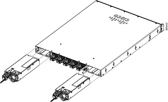
The switch chassis has two slots in which you can install power supplies using any of the following combinations:
-
Two AC, two DC or AC-DC power supplies
-
One AC-input power supply or one DC-input power supply (leaving the blank cover on the other slot)
 Note |
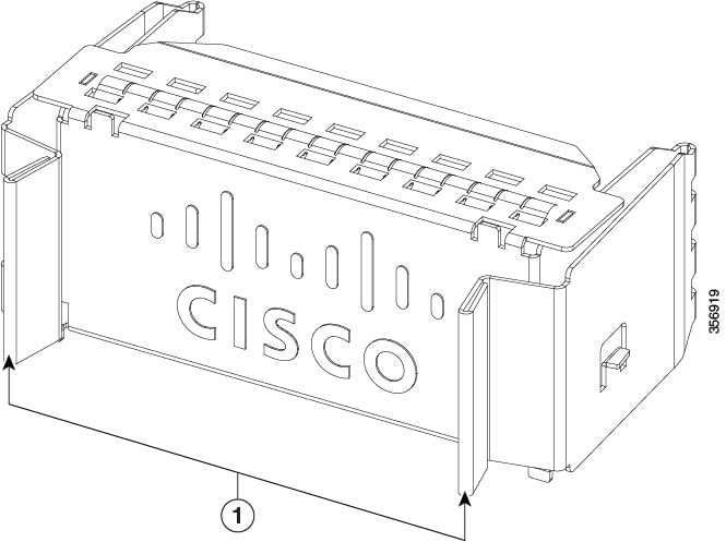
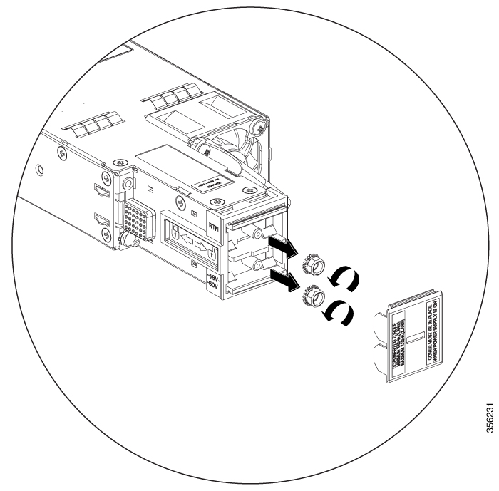
If you leave any power supply slots empty, you must ensure that the blank cover (Part Numbers PWR-C4-BLANK, C9K-PWR-C4-BLANK, C9K-PWR-C5-BLANK and PWR-C6-BLANK) is installed in that slot to maintain the designed airflow. |
This table lists the power supply models. To understand about the power supply modules supported on different switch models, see Power Supply Slots.
| Part Number | Description |
|---|---|
|
C9K-PWR-650WAC-R |
650W AC Power Supply |
|
C9K-PWR-650WACL-R |
650W AC Power Supply |
|
PWR-C4-950WAC-R |
950W AC Power Supply |
|
C9K-PWR-1600WAC-R |
1600W AC Power Supply |
|
C9K-PWR-930WDC-R |
930W DC Power Supply |
|
C9-PWR-950WDC-R |
950W DC Power Supply |
|
C9K-PWR-1600WDC-R |
1600W DC Power Supply |
|
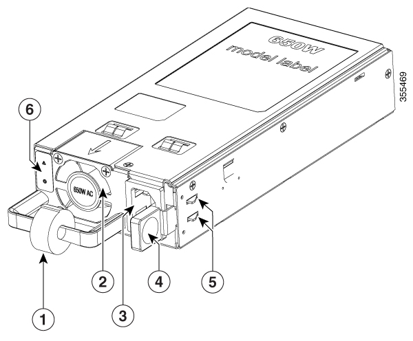
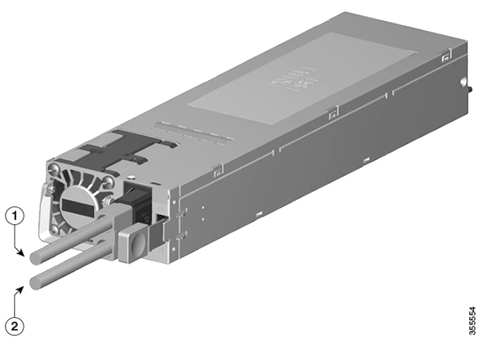
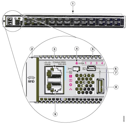
1 |
Velcro strap |
4 |
Release latch |
|
2 |
PSU fan |
5 |
Retainer clips |
|
3 |
AC power cord connector |
6 |
Power status and power supply failure LEDs |
|
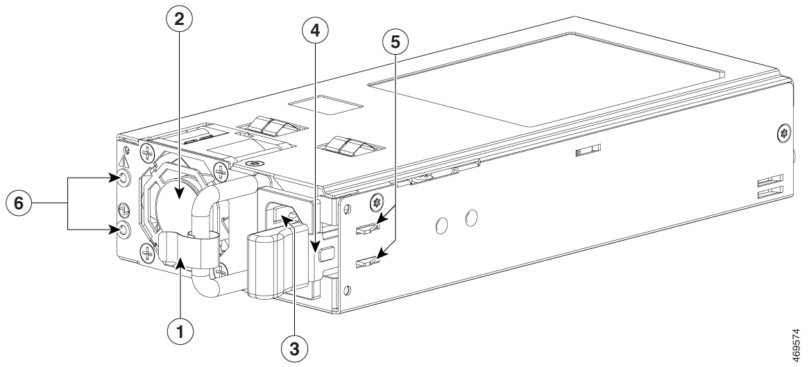
1 |
Velcro strap |
4 |
Release latch |
|
2 |
PSU fan |
5 |
Retainer clips |
|
3 |
AC power cord connector |
6 |
Power status and power supply failure LEDs |
|
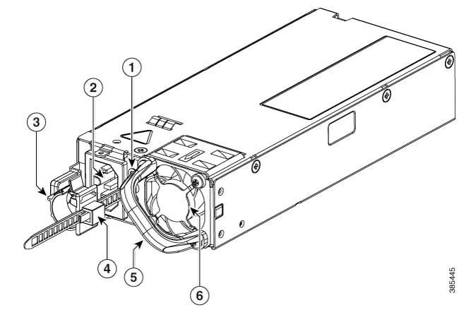
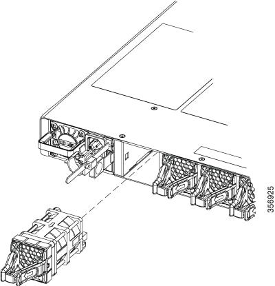
1 |
PSU LED |
4 |
Power cord retainer |
|
2 |
AC input connector |
5 |
Release handle |
|
3 |
Release latch |
6 |
PSU fan |
|
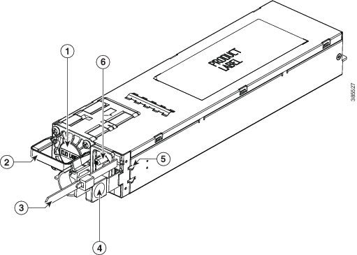
1 |
PSU fan |
4 |
Release latch |
|
2 |
Release handle |
5 |
Retainer clips |
|
3 |
Cable tie |
6 |
AC input connector |
|
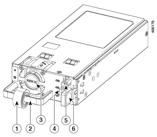
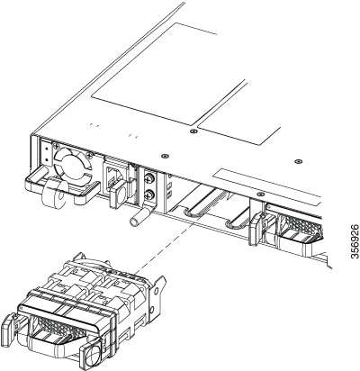
1 |
Power cord retainer |
4 |
DC+ connector |
|
2 |
Release handle |
5 |
DC- connector |
|
3 |
PSU fan |
6 |
Release latch |
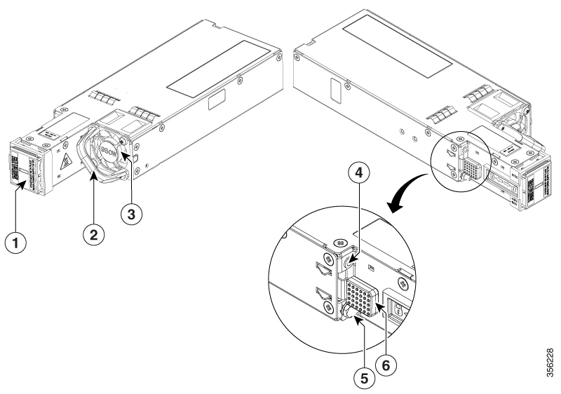
|
1 |
DC input connector |
4 |
PSU LED |
|
2 |
Release handle |
5 |
Grounding terminal |
|
3 |
PSU fan |
6 |
Release latch |
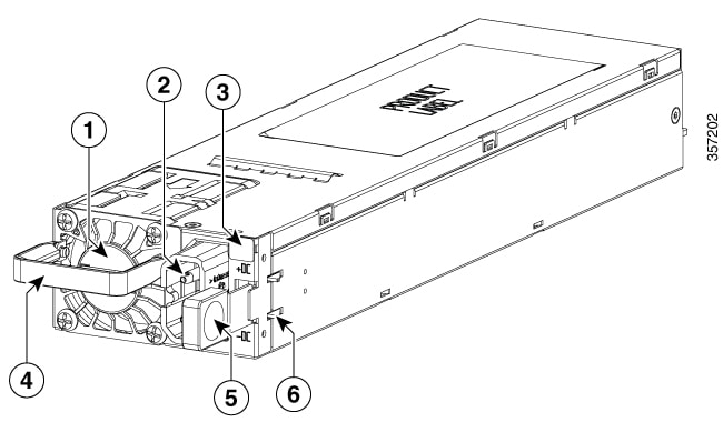
|
1 |
PSU fan |
4 |
Release handle |
|
2 |
DC input connector |
5 |
Release latch |
|
3 |
PSU LED |
6 |
Retainer clips |
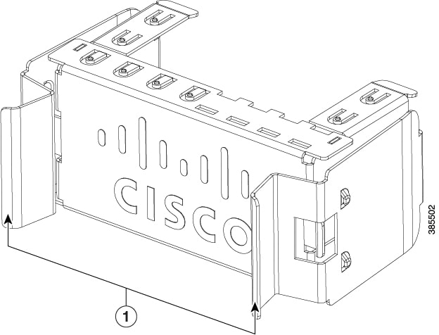
|
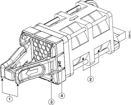
1 |
Release handles |

The power supplies can work together in Redundant Mode, in which each power supply operates at approximately 50 percent of its capacity, no greater than 60 percent and no less than 40 percent. If one power supply fails, the other power supply can provide power for the entire system on its own. This is the default and recommended mode.
Power supply modules LED
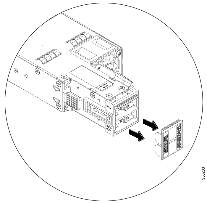
The AC and DC power supply modules except the 1600W AC and DC power supply modules, have the following LEDs:
-
Green indicating the power status
-
Amber indicating the power supply failure
|
LED |
Status |
Description |
|---|---|---|
|
Unlit |
Off |
No input power. |
|
Green |
Blinking |
12V aux output is on; 12V main output is off. |
|
Solid |
Both 12V aux output and 12V main output are on; Power supply is functioning normally. |
|
|
Amber |
Blinking |
Warning detected. OR AC power cord is not inserted properly. |
|
Solid |
Critical error detected. |
The 1600W AC and DC power supply modules have a bi-color (green/amber) LED to indicate the status of the power supplies.
|
LED Status |
Description |
|---|---|
|
Off |
No input power. |
|
Solid amber |
Critical error detected; PSU 12V main output is off. |
|
Solid green |
Both 12V aux output and 12V main output are on; Power supply is functioning normally. |
|
1Hz blinking amber |
Warning detected; PSU 12V main output is on. |
|
2Hz blinking green |
PSU 12V main output is off and 12V aux output is on. |


 Feedback