The documentation set for this product strives to use bias-free language. For the purposes of this documentation set, bias-free is defined as language that does not imply discrimination based on age, disability, gender, racial identity, ethnic identity, sexual orientation, socioeconomic status, and intersectionality. Exceptions may be present in the documentation due to language that is hardcoded in the user interfaces of the product software, language used based on RFP documentation, or language that is used by a referenced third-party product. Learn more about how Cisco is using Inclusive Language.
Your software release
may not support all the features documented in this module. For the latest
caveats and feature information, see Bug Search Tool and the release notes for
your platform and software release. To find information about the features
documented in this module, and to see a list of the releases in which each
feature is supported, see the feature information table at the end of this
module.
Use Cisco Feature
Navigator to find information about platform support and Cisco software image
support. To access Cisco Feature Navigator, go to
http://www.cisco.com/go/cfn.
An account on Cisco.com is not required.
Restrictions for
Configuring UDLD
The following are
restrictions for configuring UniDirectional Link Detection (UDLD):
A UDLD-capable
port cannot detect a unidirectional link if it is connected to a UDLD-incapable
port of another
switch.
When configuring
the mode (normal or aggressive), make sure that the same mode is configured on
both sides of the link.
UDLD is not supported on ATM ports.
Caution
Loop guard works only on
point-to-point links. We recommend that each end of the link has a directly
connected device that is running STP.
Information About UDLD
UniDirectional Link Detection (UDLD) is a Layer 2 protocol that enables devices connected through fiber-optic or twisted-pair
Ethernet cables to monitor the physical configuration of the cables and detect when a unidirectional link exists. All connected
devices must support UDLD for the protocol to successfully identify and disable unidirectional links. When UDLD detects a
unidirectional link, it disables the affected port and alerts you. Unidirectional links can cause a variety of problems, including
spanning-tree topology loops.
Modes of Operation
UDLD supports two modes of operation: normal (the default) and aggressive. In normal mode, UDLD can detect unidirectional
links due to misconnected ports on fiber-optic connections. In aggressive mode, UDLD can also detect unidirectional links
due to one-way traffic on fiber-optic and twisted-pair links and to misconnected ports on fiber-optic links.
In normal and aggressive modes, UDLD works with the Layer 1 mechanisms to learn the physical status of a link. At Layer 1,
autonegotiation takes care of physical signaling and fault detection. UDLD performs tasks that autonegotiation cannot perform,
such as detecting the identities of neighbors and shutting down misconnected ports. When you enable both autonegotiation and
UDLD, the Layer 1 and Layer 2 detections work together to prevent physical and logical unidirectional connections and the
malfunctioning of other protocols.
A unidirectional link occurs whenever traffic sent by a local device is received by its neighbor but traffic from the neighbor
is not received by the local device.
Normal Mode
In normal mode, UDLD detects
a unidirectional link when fiber strands in a fiber-optic port are misconnected
and the Layer 1 mechanisms do not detect this misconnection. If the ports are
connected correctly but the traffic is one way, UDLD does not detect the
unidirectional link because the Layer 1 mechanism, which is supposed to detect
this condition, does not do so. In this case, the logical link is considered
undetermined, and UDLD does not disable the port.
When UDLD is in normal mode,
if one of the fiber strands in a pair is disconnected, as long as
autonegotiation is active, the link does not stay up because the Layer 1
mechanisms detects a physical problem with the link. In this case, UDLD does
not take any action and the logical link is considered undetermined.
In
normal mode, when UDLD is in the advertisement or in the detection phase and
all the neighbor cache entries are aged out, UDLD restarts the link-up sequence
to resynchronize with any potentially out-of-sync neighbors.
Aggressive
Mode
In aggressive mode, UDLD
detects a unidirectional link by using the previous detection methods. UDLD in
aggressive mode can also detect a unidirectional link on a point-to-point link
on which no failure between the two devices is allowed. It can also detect a
unidirectional link when one of these problems exists:
On fiber-optic or
twisted-pair links, one of the ports cannot send or receive traffic.
On fiber-optic or
twisted-pair links, one of the ports is down while the other is up.
One of the fiber strands in
the cable is disconnected.
In these cases, UDLD disables
the affected port.
In a point-to-point link,
UDLD hello packets can be considered as a heart beat whose presence guarantees
the health of the link. Conversely, the loss of the heart beat means that the
link must be shut down if it is not possible to reestablish a bidirectional
link.
If both fiber strands in a
cable are working normally from a Layer 1 perspective, UDLD in aggressive mode
detects whether those fiber strands are connected correctly and whether traffic
is flowing bidirectionally between the correct neighbors. This check cannot be
performed by autonegotiation because autonegotiation operates at Layer 1.
If you enable aggressive mode
when all the neighbors of a port have aged out either in the advertisement or
in the detection phase, UDLD restarts the link-up sequence to resynchronize
with any potentially out-of-sync neighbor. UDLD shuts down the port if, after
the fast train of messages, the link state is still undetermined.
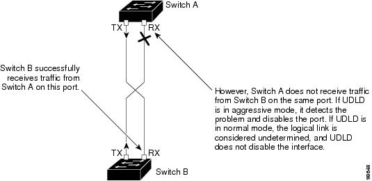
The
following figure shows an example of a unidirectional link condition.
Figure 1. UDLD Detection of a Unidirectional Link
Methods to Detect Unidirectional Links
UDLD operates by using two methods:
Neighbor database maintenance
Event-driven detection and echoing
Neighbor Database Maintenance
UDLD learns about other UDLD-capable neighbors by periodically sending a hello packet (also called an advertisement or probe)
on every active port to keep each device informed about its neighbors.
When the switch receives a hello message, it caches the information until the age time (hold time or time-to-live) expires. If the switch receives a new hello message before an older cache entry ages, the switch replaces the older entry with the new one.
Whenever a port is disabled and UDLD is running, whenever UDLD is disabled on a port, or whenever the switch is reset, UDLD clears all existing cache entries for the ports affected by the configuration change. UDLD sends at least
one message to inform the neighbors to flush the part of their caches affected by the status change. The message is intended
to keep the caches synchronized.
Event-Driven Detection and Echoing
UDLD relies on echoing as its detection operation. Whenever a UDLD device learns about a new neighbor or receives a resynchronization
request from an out-of-sync neighbor, it restarts the detection window on its side of the connection and sends echo messages
in reply. Because this behavior is the same on all UDLD neighbors, the sender of the echoes expects to receive an echo in
reply.
If the detection window ends and no valid reply message is received, the link might shut down, depending on the UDLD mode.
When UDLD is in normal mode, the link might be considered undetermined and might not be shut down. When UDLD is in aggressive
mode, the link is considered unidirectional, and the port is disabled.
UDLD Reset Options
If an interface becomes disabled by UDLD, you can use one of the following options to reset UDLD:
The udld reset interface configuration command.
The shutdown interface configuration command followed by the no shutdown interface configuration command restarts the disabled port.
The no udld {aggressive | enable } global configuration command followed by the udld {aggressive | enable } global configuration command reenables the disabled ports.
The no udld port interface configuration command followed by the udld port [aggressive ] interface configuration command reenables the disabled fiber-optic port.
The errdisable recovery cause udld global configuration command enables the timer to automatically recover from the UDLD error-disabled state, and the errdisable recovery interval interval global configuration command specifies the time to recover from the UDLD error-disabled state.
Default UDLD Configuration
Table 1. Default UDLD Configuration
Feature
Default Setting
UDLD global enable state
Globally disabled
UDLD per-port enable state for fiber-optic media
Disabled on all Ethernet fiber-optic ports
UDLD per-port enable state for twisted-pair (copper) media
Disabled on all Ethernet 10/100 and 1000BASE-TX ports
UDLD aggressive mode
Disabled
How to Configure UDLD
Enabling UDLD Globally
Follow these steps
to enable UDLD in the aggressive or normal mode and to set the configurable
message timer on all fiber-optic ports on the
switch.
Procedure
Command or Action
Purpose
Step 1
configure
terminal
Example:
Switch# configure terminal
Enters global
configuration mode.
Step 2
udld
{aggressive |
enable |
message time message-timer-interval}
Example:
Switch(config)# udld enable
message time 10
Specifies the UDLD
mode of operation:
aggressive —Enables UDLD in aggressive mode on all
fiber-optic ports.
enable —Enables UDLD in normal mode on all
fiber-optic ports on the
switch. UDLD is disabled by default.
An individual
interface configuration overrides the setting of the
udld enable global configuration command.
message time message-timer-interval—Configures the period of
time between UDLD probe messages on ports that are in the advertisement phase
and are detected to be bidirectional. The range is from 1 to 90 seconds; the
default value is 15.
Note
The global UDLD setting is
automatically applied to
switches that join the
switch stack.
Note
This command affects
fiber-optic ports only. Use the
udld interface configuration command to enable
UDLD on other port types.
Use the
no form of this
command, to disable UDLD.
Step 3
end
Example:
Switch(config)# end
Returns to
privileged EXEC mode.
Enabling UDLD on an Interface
Follow these steps either to enable UDLD in the aggressive or normal mode or to disable UDLD on a port.
Procedure
Command or Action
Purpose
Step 1
configure terminal
Example:
Switch# configure terminal
Enters global configuration mode.
Step 2
interface interface-id
Example:
Switch(config)# interface
gigabitethernet 1/0/1
Specifies the port to be enabled for UDLD, and enters interface configuration mode.
Step 3
udld port [aggressive ]
Example:
Switch(config-if)# udld port aggressive
UDLD is disabled by default.
udld port —Enables UDLD in normal mode on the specified port.
udld port aggressive —(Optional) Enables UDLD in aggressive mode on the specified port.
Note
Use the no udld port interface configuration command to disable UDLD on a specified fiber-optic port.
Step 4
end
Example:
Switch(config-if)# end
Returns to privileged EXEC mode.
Monitoring and Maintaining UDLD
Command
Purpose
show udld [interface-id | neighbors ]
Displays the UDLD status for the specified port or for all ports.
The Cisco
Support website provides extensive online resources, including documentation
and tools for troubleshooting and resolving technical issues with Cisco
products and technologies.
To receive
security and technical information about your products, you can subscribe to
various services, such as the Product Alert Tool (accessed from Field Notices),
the Cisco Technical Services Newsletter, and Really Simple Syndication (RSS)
Feeds.
Access to
most tools on the Cisco Support website requires a Cisco.com user ID and
password.

 Feedback