Restrictions for Administering the Switch
Do not use switches running the Cisco IOS XE release images as VPN termination points. Use a router or Cisco Adaptive Security Appliance (ASA) as a VPN termination point .
The documentation set for this product strives to use bias-free language. For the purposes of this documentation set, bias-free is defined as language that does not imply discrimination based on age, disability, gender, racial identity, ethnic identity, sexual orientation, socioeconomic status, and intersectionality. Exceptions may be present in the documentation due to language that is hardcoded in the user interfaces of the product software, language used based on RFP documentation, or language that is used by a referenced third-party product. Learn more about how Cisco is using Inclusive Language.
Do not use switches running the Cisco IOS XE release images as VPN termination points. Use a router or Cisco Adaptive Security Appliance (ASA) as a VPN termination point .
You can manage the system time and date on your device using automatic configuration methods (RTC and NTP), or manual configuration methods.
 Note |
For complete syntax and usage information for the commands used in this section, see the Cisco IOS Configuration Fundamentals Command Referenceon Cisco.com. |
The basis of the time service is the system clock. This clock runs from the moment the system starts up and keeps track of the date and time.
The system clock can then be set from these sources:
NTP
Manual configuration
The system clock can provide time to these services:
User show commands
Logging and debugging messages
The system clock keeps track of time internally based on Coordinated Universal Time (UTC), also known as Greenwich Mean Time (GMT). You can configure information about the local time zone and summer time (daylight saving time) so that the time appears correctly for the local time zone.
The system clock keeps track of whether the time is authoritative or not (that is, whether it has been set by a time source considered to be authoritative). If it is not authoritative, the time is available only for display purposes and is not redistributed.
The NTP is designed to time-synchronize a network of devices. NTP runs over User Datagram Protocol (UDP), which runs over IP. NTP is documented in RFC 1305.
An NTP network usually gets its time from an authoritative time source, such as a radio clock or an atomic clock attached to a time server. NTP then distributes this time across the network. NTP is extremely efficient; no more than one packet per minute is necessary to synchronize two devices to within a millisecond of one another.
NTP uses the concept of a stratum to describe how many NTP hops away a device is from an authoritative time source. A stratum 1 time server has a radio or atomic clock directly attached, a stratum 2 time server receives its time through NTP from a stratum 1 time server, and so on. A device running NTP automatically chooses as its time source the device with the lowest stratum number with which it communicates through NTP. This strategy effectively builds a self-organizing tree of NTP speakers.
NTP avoids synchronizing to a device whose time might not be accurate by never synchronizing to a device that is not synchronized. NTP also compares the time reported by several devices and does not synchronize to a device whose time is significantly different than the others, even if its stratum is lower.
The communications between devices running NTP (known as associations) are usually statically configured; each device is given the IP address of all devices with which it should form associations. Accurate timekeeping is possible by exchanging NTP messages between each pair of devices with an association. However, in a LAN environment, NTP can be configured to use IP broadcast messages instead. This alternative reduces configuration complexity because each device can simply be configured to send or receive broadcast messages. However, in that case, information flow is one-way only.
The time kept on a device is a critical resource; you should use the security features of NTP to avoid the accidental or malicious setting of an incorrect time. Two mechanisms are available: an access list-based restriction scheme and an encrypted authentication mechanism.
Cisco’s implementation of NTP does not support stratum 1 service; it is not possible to connect to a radio or atomic clock. We recommend that the time service for your network be derived from the public NTP servers available on the IP Internet.
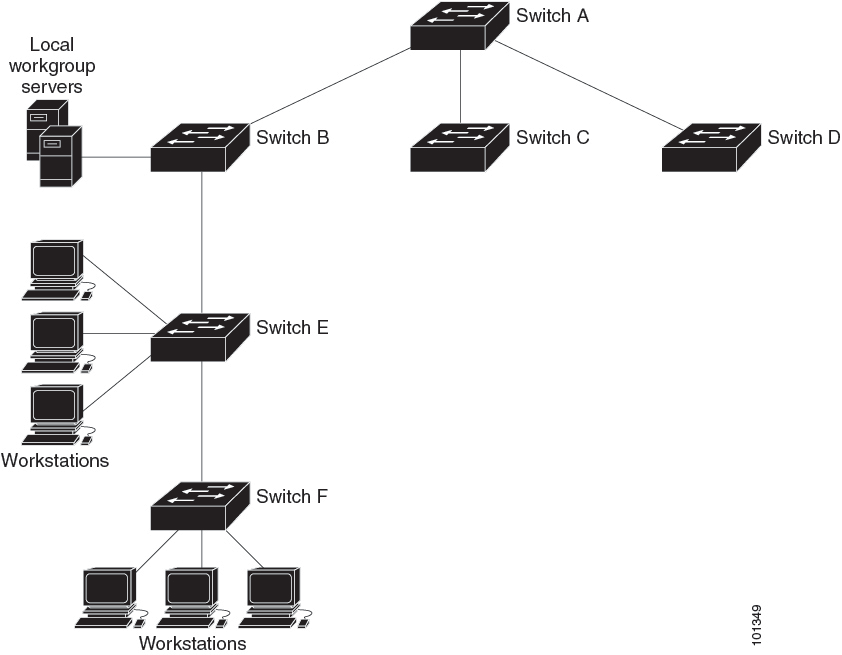
The figure below shows a typical network example using NTP. Device A is the NTP primary (formerly known as NTP primary), with the Device B, C, and D configured in NTP server mode, in server association with Device A. Device E is configured as an NTP peer to the upstream and downstream Device, Device B and Device F, respectively.
If the network is isolated from the Internet, Cisco’s implementation of NTP allows a device to act as if it is synchronized through NTP, when in fact it has learned the time by using other means. Other devices then synchronize to that device through NTP.
When multiple sources of time are available, NTP is always considered to be more authoritative. NTP time overrides the time set by any other method.
Several manufacturers include NTP software for their host systems, and a publicly available version for systems running UNIX and its various derivatives is also available. This software allows host systems to be time-synchronized as well.
NTP uses the concept of a stratum to describe how many NTP hops away a device is from an authoritative time source. A stratum 1 time server has a radio or atomic clock directly attached, a stratum 2 time server receives its time through NTP from a stratum 1 time server, and so on. A device running NTP automatically chooses as its time source the device with the lowest stratum number with which it communicates through NTP. This strategy effectively builds a self-organizing tree of NTP speakers.
NTP avoids synchronizing to a device whose time might not be accurate by never synchronizing to a device that is not synchronized. NTP also compares the time reported by several devices and does not synchronize to a device whose time is significantly different than the others, even if its stratum is lower.
The communications between devices running NTP (known as associations) are usually statically configured; each device is given the IP address of all devices with which it should form associations. Accurate timekeeping is possible by exchanging NTP messages between each pair of devices with an association. However, in a LAN environment, NTP can be configured to use IP broadcast messages instead. This alternative reduces configuration complexity because each device can simply be configured to send or receive broadcast messages. However, in that case, information flow is one-way only.
Networking devices running NTP can be configured to operate in variety of association modes when synchronizing time with reference time sources. A networking device can obtain time information on a network in two ways—by polling host servers and by listening to NTP broadcasts. This section focuses on the poll-based association modes. Broadcast-based NTP associations are discussed in the Broadcast-Based NTP Associations section.
The following are the two most commonly used poll-based association modes:
Client mode
Symmetric active mode
The client and the symmetric active modes should be used when NTP is required to provide a high level of time accuracy and reliability.
When a networking device is operating in the client mode, it polls its assigned time-serving hosts for the current time. The networking device will then pick a host from among all the polled time servers to synchronize with. Because the relationship that is established in this case is a client-host relationship, the host will not capture or use any time information sent by the local client device. This mode is most suited for file-server and workstation clients that are not required to provide any form of time synchronization to other local clients. Use the ntp server command to individually specify the time server that you want your networking device to consider synchronizing with and to set your networking device to operate in the client mode.
When a networking device is operating in the symmetric active mode, it polls its assigned time-serving hosts for the current time and it responds to polls by its hosts. Because this is a peer-to-peer relationship, the host will also retain time-related information of the local networking device that it is communicating with. This mode should be used when a number of mutually redundant servers are interconnected via diverse network paths. Most stratum 1 and stratum 2 servers on the Internet adopt this form of network setup. Use the ntp peer command to individually specify the time serving hosts that you want your networking device to consider synchronizing with and to set your networking device to operate in the symmetric active mode.
The specific mode that you should set for each of your networking devices depends primarily on the role that you want them to assume as a timekeeping device (server or client) and the device’s proximity to a stratum 1 timekeeping server.
A networking device engages in polling when it is operating as a client or a host in the client mode or when it is acting as a peer in the symmetric active mode. Although polling does not usually place a burden on memory and CPU resources such as bandwidth, an exceedingly large number of ongoing and simultaneous polls on a system can seriously impact the performance of a system or slow the performance of a given network. To avoid having an excessive number of ongoing polls on a network, you should limit the number of direct, peer-to-peer or client-to-server associations. Instead, you should consider using NTP broadcasts to propagate time information within a localized network.
Broadcast-based NTP associations should be used when time accuracy and reliability requirements are modest and if your network is localized and has more than 20 clients. Broadcast-based NTP associations are also recommended for use on networks that have limited bandwidth, system memory, or CPU resources.
A networking device operating in the broadcast client mode does not engage in any polling. Instead, it listens for NTP broadcast packets that are transmitted by broadcast time servers. Consequently, time accuracy can be marginally reduced because time information flows only one way.
Use the ntp broadcast client command to set your networking device to listen for NTP broadcast packets propagated through a network. For broadcast client mode to work, the broadcast server and its clients must be located on the same subnet. You must enable the time server that transmits NTP broadcast packets on the interface of the given device by using the ntp broadcast command.
The time kept on a device is a critical resource; you should use the security features of NTP to avoid the accidental or malicious setting of an incorrect time. Two mechanisms are available: an access list-based restriction scheme and an encrypted authentication mechanism.
The access list-based restriction scheme allows you to grant or deny certain access privileges to an entire network, a subnet within a network, or a host within a subnet. To define an NTP access group, use the ntp access-group command in global configuration mode.
The access group options are scanned in the following order, from least restrictive to the most restrictive:
ipv4 —Configures IPv4 access lists.
ipv6 —Configures IPv6 access lists.
peer —Allows time requests and NTP control queries, and allows the system to synchronize itself to a system whose address passes the access list criteria.
serve —Allows time requests and NTP control queries, but does not allow the system to synchronize itself to a system whose address passes the access list criteria.
serve-only —Allows only time requests from a system whose address passes the access list criteria.
query-only —Allows only NTP control queries from a system whose address passes the access list criteria.
If the source IP address matches the access lists for more than one access type, the first type is granted access. If no access groups are specified, all access types are granted access to all systems. If any access groups are specified, only the specified access types will be granted access.
For details on NTP control queries, see RFC 1305 (NTP Version 3).
The encrypted NTP authentication scheme should be used when a reliable form of access control is required. Unlike the access list-based restriction scheme that is based on IP addresses, the encrypted authentication scheme uses authentication keys and an authentication process to determine if NTP synchronization packets sent by designated peers or servers on a local network are deemed as trusted before the time information that they carry along with them is accepted.
The authentication process begins from the moment an NTP packet is created. Cryptographic checksum keys are generated using the message digest algorithm 5 (MD5) and are embedded into the NTP synchronization packet that is sent to a receiving client. Once a packet is received by a client, its cryptographic checksum key is decrypted and checked against a list of trusted keys. If the packet contains a matching authentication key, the time-stamp information that is contained within the packet is accepted by the receiving client. NTP synchronization packets that do not contain a matching authenticator key are ignored.
Note |
In large networks, where many trusted keys must be configured, the Range of Trusted Key Configuration feature enables configuring multiple keys simultaneously. |
It is important to note that the encryption and decryption processes used in NTP authentication can be very CPU-intensive and can seriously degrade the accuracy of the time that is propagated within a network. If your network setup permits a more comprehensive model of access control, you should consider the use of the access list-based form of control.
After NTP authentication is properly configured, your networking device will synchronize with and provide synchronization only to trusted time sources.
Network Time Protocol (NTP) services are disabled on all interfaces by default. NTP is enabled globally when any NTP commands are entered. You can selectively prevent NTP packets from being received through a specific interface by using the ntp disable command in interface configuration mode.
When the system sends an NTP packet, the source IP address is normally set to the address of the interface through which the NTP packet is sent. Use the ntp source interface command in global configuration mode to configure a specific interface from which the IP source address will be taken.
This interface will be used for the source address for all packets sent to all destinations. If a source address is to be used for a specific association, use the source keyword in the ntp peer or ntp server command.
Implementation of NTP does not support stratum 1 service; it is not possible to connect to a radio or atomic clock. We recommend that the time service for your network be derived from the public NTP servers available on the IP Internet.
If the network is isolated from the Internet, NTP allows a device to act as if it is synchronized through NTP, when in fact it has learned the time by using other means. Other devices then synchronize to that device through NTP.
When multiple sources of time are available, NTP is always considered to be more authoritative. NTP time overrides the time set by any other method.
Several manufacturers include NTP software for their host systems, and a publicly available version for systems running UNIX and its various derivatives is also available. This software allows host systems to be time-synchronized as well.
NTP version 4 is implemented on the device. NTPv4 is an extension of NTP version 3. NTPv4 supports both IPv4 and IPv6 and is backward-compatible with NTPv3.
NTPv4 provides these capabilities:
Support for IPv6.
Improved security compared to NTPv3. The NTPv4 protocol provides a security framework based on public key cryptography and standard X509 certificates.
Automatic calculation of the time-distribution hierarchy for a network. Using specific multicast groups, NTPv4 automatically configures the hierarchy of the servers to achieve the best time accuracy for the lowest bandwidth cost. This feature leverages site-local IPv6 multicast addresses.
For details about configuring NTPv4, see the Implementing NTPv4 in IPv6 chapter of the Cisco IOS IPv6 Configuration Guide, Release 12.4T.
You configure the system name on the Device to identify it. By default, the system name and prompt are Switch.
If you have not configured a system prompt, the first 20 characters of the system name are used as the system prompt. A greater-than symbol [>] is appended. The prompt is updated whenever the system name changes.
For complete syntax and usage information for the commands used in this section, see the Cisco IOS Configuration Fundamentals Command Reference, Release 12.4 and the Cisco IOS IP Command Reference, Volume 2 of 3: Routing Protocols, Release 12.4.
The default switch system name and prompt is Switch.
The DNS protocol controls the Domain Name System (DNS), a distributed database with which you can map hostnames to IP addresses. When you configure DNS on your device, you can substitute the hostname for the IP address with all IP commands, such as ping , telnet , connect , and related Telnet support operations.
IP defines a hierarchical naming scheme that allows a device to be identified by its location or domain. Domain names are pieced together with periods (.) as the delimiting characters. For example, Cisco Systems is a commercial organization that IP identifies by a com domain name, so its domain name is cisco.com. A specific device in this domain, for example, the File Transfer Protocol (FTP) system is identified as ftp.cisco.com.
To keep track of domain names, IP has defined the concept of a domain name server, which holds a cache (or database) of names mapped to IP addresses. To map domain names to IP addresses, you must first identify the hostnames, specify the name server that is present on your network, and enable the DNS.
|
Feature |
Default Setting |
|---|---|
|
DNS enable state |
Enabled. |
|
DNS default domain name |
None configured. |
|
DNS servers |
No name server addresses are configured. |
You can configure a message-of-the-day (MOTD) and a login banner. The MOTD banner is displayed on all connected terminals at login and is useful for sending messages that affect all network users (such as impending system shutdowns).
The login banner is also displayed on all connected terminals. It appears after the MOTD banner and before the login prompts.
Note |
For complete syntax and usage information for the commands used in this section, see the Cisco IOS Configuration Fundamentals Command Reference, Release 12.4. |
The MOTD and login banners are not configured.
The MAC address table contains address information that the device uses to forward traffic between ports. All MAC addresses in the address table are associated with one or more ports. The address table includes these types of addresses:
Dynamic address—A source MAC address that the device learns and then ages when it is not in use.
Static address—A manually entered unicast address that does not age and that is not lost when the device resets.
The address table lists the destination MAC address, the associated VLAN ID, and port number associated with the address and the type (static or dynamic).
Note |
For complete syntax and usage information for the commands used in this section, see the command reference for this release. |
With multiple MAC addresses supported on all ports, you can connect any port on the device to other network devices. The device provides dynamic addressing by learning the source address of packets it receives on each port and adding the address and its associated port number to the address table. As devices are added or removed from the network, the device updates the address table, adding new dynamic addresses and aging out those that are not in use.
The aging interval is globally configured. However, the device maintains an address table for each VLAN, and STP can accelerate the aging interval on a per-VLAN basis.
The device sends packets between any combination of ports, based on the destination address of the received packet. Using the MAC address table, the device forwards the packet only to the port associated with the destination address. If the destination address is on the port that sent the packet, the packet is filtered and not forwarded. The device always uses the store-and-forward method: complete packets are stored and checked for errors before transmission.
All addresses are associated with a VLAN. An address can exist in more than one VLAN and have different destinations in each. Unicast addresses, for example, could be forwarded to port 1 in VLAN 1 and ports 9, 10, and 1 in VLAN 5.
Each VLAN maintains its own logical address table. A known address in one VLAN is unknown in another until it is learned or statically associated with a port in the other VLAN.
The following table shows the default settings for the MAC address table.
|
Feature |
Default Setting |
|---|---|
|
Aging time |
300 seconds |
|
Dynamic addresses |
Automatically learned |
|
Static addresses |
None configured |
To communicate with a device (over Ethernet, for example), the software first must learn the 48-bit MAC address or the local data link address of that device. The process of learning the local data link address from an IP address is called address resolution .
The Address Resolution Protocol (ARP) associates a host IP address with the corresponding media or MAC addresses and the VLAN ID. Using an IP address, ARP finds the associated MAC address. When a MAC address is found, the IP-MAC address association is stored in an ARP cache for rapid retrieval. Then the IP datagram is encapsulated in a link-layer frame and sent over the network. Encapsulation of IP datagrams and ARP requests and replies on IEEE 802 networks other than Ethernet is specified by the Subnetwork Access Protocol (SNAP). By default, standard Ethernet-style ARP encapsulation (represented by the arpa keyword) is enabled on the IP interface.
ARP entries added manually to the table do not age and must be manually removed.
For CLI procedures, see the Cisco IOS Release 12.4 documentation on Cisco.com.
System time remains accurate through restarts and reboot, however, you can manually configure the time and date after the system is restarted.
We recommend that you use manual configuration only when necessary. If you have an outside source to which the device can synchronize, you do not need to manually set the system clock.
Note |
You must reconfigure this setting if you have manually configured the system clock before the active switch fails and a different stack member assumes the role of active switch. |
If you have an outside source on the network that provides time services, such as an NTP server, you do not need to manually set the system clock.
Follow these steps to set the system clock:
| Command or Action | Purpose | |
|---|---|---|
|
Step 1 |
enable Example: |
Enables privileged EXEC mode.
|
|
Step 2 |
Use one of the following:
Example: |
Manually set the system clock using one of these formats:
|
| Command or Action | Purpose | |
|---|---|---|
|
Step 1 |
enable Example: |
Enables privileged EXEC mode.
|
|
Step 2 |
configure terminal Example: |
Enters global configuration mode. |
|
Step 3 |
clock timezone zone hours-offset [minutes-offset] Example: |
Sets the time zone. Internal time is kept in Coordinated Universal Time (UTC), so this command is used only for display purposes and when the time is manually set.
|
|
Step 4 |
end Example: |
Returns to privileged EXEC mode. |
|
Step 5 |
show running-config Example: |
Verifies your entries. |
|
Step 6 |
copy running-config startup-config Example: |
(Optional) Saves your entries in the configuration file. |
To configure summer time (daylight saving time) in areas where it starts and ends on a particular day of the week each year, perform this task:
| Command or Action | Purpose | |
|---|---|---|
|
Step 1 |
enable Example: |
Enables privileged EXEC mode.
|
|
Step 2 |
configure terminal Example: |
Enters global configuration mode. |
|
Step 3 |
clock summer-time zone date date month year hh:mm date month year hh:mm [offset]] Example: |
Configures summer time to start and end on specified days every year. |
|
Step 4 |
clock summer-time zone recurring [week day month hh:mm week day month hh:mm [offset]] Example: |
Configures summer time to start and end on the specified days every year. All times are relative to the local time zone. The start time is relative to standard time. The end time is relative to summer time. Summer time is disabled by default. If you specify clock summer-time zone recurring without parameters, the summer time rules default to the United States rules. If the starting month is after the ending month, the system assumes that you are in the southern hemisphere.
|
|
Step 5 |
end Example: |
Returns to privileged EXEC mode. |
|
Step 6 |
show running-config Example: |
Verifies your entries. |
|
Step 7 |
copy running-config startup-config Example: |
(Optional) Saves your entries in the configuration file. |
Follow these steps if summer time in your area does not follow a recurring pattern (configure the exact date and time of the next summer time events):
| Command or Action | Purpose | |
|---|---|---|
|
Step 1 |
enable Example: |
Enables privileged EXEC mode.
|
|
Step 2 |
configure terminal Example: |
Enters global configuration mode. |
|
Step 3 |
clock summer-time zone date[ month date year hh:mm month date year hh:mm [offset]] orclock summer-time zone date [date month year hh:mm date month year hh:mm [offset]] |
Configures summer time to start on the first date and end on the second date.
|
|
Step 4 |
end Example: |
Returns to privileged EXEC mode. |
|
Step 5 |
show running-config Example: |
Verifies your entries. |
|
Step 6 |
copy running-config startup-config Example: |
(Optional) Saves your entries in the configuration file. |
The device does not have a hardware-supported clock and cannot function as an NTP primary clock to which peers synchronize themselves when an external NTP source is not available. The device also has no hardware support for a calendar. As a result, the ntp update-calendar and the ntp master commands in global configuration mode are not available.
These following sections provide configuration information on NTP:
shows the default NTP configuration.
|
Feature |
Default Setting |
|---|---|
|
NTP authentication |
Disabled. No authentication key is specified. |
|
NTP peer or server associations |
None configured. |
|
NTP broadcast service |
Disabled; no interface sends or receives NTP broadcast packets. |
|
NTP access restrictions |
No access control is specified. |
|
NTP packet source IP address |
The source address is set by the outgoing interface. |
NTP is enabled on all interfaces by default. All interfaces receive NTP packets.
To configure NTP authentication, perform this procedure:
| Command or Action | Purpose | |
|---|---|---|
|
Step 1 |
enable Example: |
Enables privileged EXEC mode. Enter your password if prompted. |
|
Step 2 |
configure terminal Example: |
Enters global configuration mode. |
|
Step 3 |
ntp authenticate Example: |
Enables NTP authentication. Use the no form of this command to disable NTP authentication |
|
Step 4 |
ntp authentication-key number md5 value Example: |
Defines the authentication keys.
Use the no form of this command to remove authentication key. |
|
Step 5 |
ntp trusted-key key-number Example: |
Defines trusted authentication keys that a peer NTP device must provide in its NTP packets for this device to synchronize to it. Use the no form of this command to disable trusted authentication. |
|
Step 6 |
ntp server ip-address key key-id [prefer] Example: |
Allows the software clock to be synchronized by an NTP time server.
Use the no form of this command to remove a server association. |
|
Step 7 |
end Example: |
Returns to privileged EXEC mode. |
To configure poll-based NTP associations, perform this procedure:
| Command or Action | Purpose | |
|---|---|---|
|
Step 1 |
enable Example: |
Enables privileged EXEC mode. Enter your password if prompted. |
|
Step 2 |
configure terminal Example: |
Enters global configuration mode. |
|
Step 3 |
[no] ntp peer ip-address [version number] [key key-id] [source interface] [prefer] Example: |
Configures the device system clock to synchronize a peer or to be synchronized by a peer (peer association).
Use the no form of this command to remove a peer association. |
|
Step 4 |
[no] ntp server ip-address [version number] [key key-id] [source interface] [prefer] Example: |
Configures the device's system clock to be synchronized by a time server (server association).
Use the no form of this command to remove a server association. |
|
Step 5 |
end Example: |
Returns to privileged EXEC mode. |
To configure broadcast-based NTP associations, perform this procedure:
| Command or Action | Purpose | |
|---|---|---|
|
Step 1 |
enable Example: |
Enables privileged EXEC mode. Enter your password if prompted. |
|
Step 2 |
configure terminal Example: |
Enters global configuration mode. |
|
Step 3 |
interface interface-id Example: |
Configures an interface and enters interface configuration mode. |
|
Step 4 |
[no] ntp broadcast [version number] [key key-id] [destination-address] Example: |
Enables the interface to send NTP broadcast packets to a peer.
Use the no form of this command to disable the interface from sending NTP broadcast packets. |
|
Step 5 |
[no] ntp broadcast client Example: |
Enables the interface to receive NTP broadcast packets. Use the no form of this command to disable the interface from receiving NTP broadcast packets. |
|
Step 6 |
exit Example: |
Returns to privileged EXEC mode. |
|
Step 7 |
[no] ntp broadcastdelay microseconds Example: |
(Optional) Change the estimated round-trip delay between the device and the NTP broadcast server The default is 3000 microseconds. The range is from 1 to 999999. Use the no form of this command to disable the interface from receiving NTP broadcast packets. |
|
Step 8 |
end Example: |
Returns to privileged EXEC mode. |
You can control NTP access on two levels as described in these sections:
To create an access group and assign a basic IP access list, perform this procedure:
| Command or Action | Purpose | |||
|---|---|---|---|---|
|
Step 1 |
enable Example: |
Enables privileged EXEC mode. Enter your password if prompted. |
||
|
Step 2 |
configure terminal Example: |
Enters global configuration mode. |
||
|
Step 3 |
[no] ntp access-group {query-only | serve-only | serve | peer} access-list-number Example: |
Create an access group, and apply a basic IP access list..
Use the no form of this command to remove access control to the switch NTP services. |
||
|
Step 4 |
access-list access-list-number permit source [source-wildcard] Example: |
Create the access list.
Use the no form of this command to remove authentication key. |
||
|
Step 5 |
end Example: |
Returns to privileged EXEC mode. |
To disable NTP packets from being received on an interface, perform this procedure:
| Command or Action | Purpose | |
|---|---|---|
|
Step 1 |
enable Example: |
Enables privileged EXEC mode. Enter your password if prompted. |
|
Step 2 |
configure terminal Example: |
Enters global configuration mode. |
|
Step 3 |
interface interface-id Example: |
Enters global configuration mode. |
|
Step 4 |
[no] ntp disable Example: |
Disables NTP packets from being received on the interface. Use the no form of this command to re-enable receipt of NTP packets on an interface. |
|
Step 5 |
end Example: |
Returns to privileged EXEC mode. |
| Command or Action | Purpose | |
|---|---|---|
|
Step 1 |
enable Example: |
Enables privileged EXEC mode.
|
|
Step 2 |
configure terminal Example: |
Enters global configuration mode. |
|
Step 3 |
hostname name Example: |
Configures a system name. When you set the system name, it is also used as the system prompt. The default setting is Switch. The name must follow the rules for ARPANET hostnames. They must start with a letter, end with a letter or digit, and have as interior characters only letters, digits, and hyphens. Names can be up to 63 characters. |
|
Step 4 |
end Example: |
Returns to priviliged EXEC mode. |
|
Step 5 |
show running-config Example: |
Verifies your entries. |
|
Step 6 |
copy running-config startup-config Example: |
(Optional) Saves your entries in the configuration file. |
If you use the device IP address as its hostname, the IP address is used and no DNS query occurs. If you configure a hostname that contains no periods (.), a period followed by the default domain name is appended to the hostname before the DNS query is made to map the name to an IP address. The default domain name is the value set by the ip domain name command in global configuration mode. If there is a period (.) in the hostname, the Cisco IOS software looks up the IP address without appending any default domain name to the hostname.
Follow these steps to set up your switch to use the DNS:
| Command or Action | Purpose | |
|---|---|---|
|
Step 1 |
enable Example: |
Enables privileged EXEC mode.
|
|
Step 2 |
configure terminal Example: |
Enters global configuration mode. |
|
Step 3 |
ip domain name name Example: |
Defines a default domain name that the software uses to complete unqualified hostnames (names without a dotted-decimal domain name). Do not include the initial period that separates an unqualified name from the domain name. At boot time, no domain name is configured; however, if the device configuration comes from a BOOTP or Dynamic Host Configuration Protocol (DHCP) server, then the default domain name might be set by the BOOTP or DHCP server (if the servers were configured with this information). |
|
Step 4 |
ip name-server server-address1 [server-address2 ... server-address6] Example: |
Specifies the address of one or more name servers to use for name and address resolution. You can specify up to six name servers. Separate each server address with a space. The first server specified is the primary server. The device sends DNS queries to the primary server first. If that query fails, the backup servers are queried. |
|
Step 5 |
ip domain lookup [nsap | source-interface interface] Example: |
(Optional) Enables DNS-based hostname-to-address translation on your device. This feature is enabled by default. If your network devices require connectivity with devices in networks for which you do not control name assignment, you can dynamically assign device names that uniquely identify your devices by using the global Internet naming scheme (DNS). |
|
Step 6 |
end Example: |
Returns to privileged EXEC mode. |
|
Step 7 |
show running-config Example: |
Verifies your entries. |
|
Step 8 |
copy running-config startup-config Example: |
(Optional) Saves your entries in the configuration file. |
You can create a single or multiline message banner that appears on the screen when someone logs in to the device
Follow these steps to configure a MOTD login banner:
| Command or Action | Purpose | |
|---|---|---|
|
Step 1 |
enable Example: |
Enables privileged EXEC mode.
|
|
Step 2 |
configure terminal Example: |
Enters global configuration mode. |
|
Step 3 |
banner motd c message c Example: |
Specifies the message of the day. c— Enters the delimiting character of your choice, for example, a pound sign (#), and press the Return key. The delimiting character signifies the beginning and end of the banner text. Characters after the ending delimiter are discarded. message— Enters a banner message up to 255 characters. You cannot use the delimiting character in the message. |
|
Step 4 |
end Example: |
Returns to privileged EXEC mode. |
|
Step 5 |
show running-config Example: |
Verifies your entries. |
|
Step 6 |
copy running-config startup-config Example: |
(Optional) Saves your entries in the configuration file. |
You can configure a login banner to be displayed on all connected terminals. This banner appears after the MOTD banner and before the login prompt.
Follow these steps to configure a login banner:
| Command or Action | Purpose | |
|---|---|---|
|
Step 1 |
enable Example: |
Enables privileged EXEC mode.
|
|
Step 2 |
configure terminal Example: |
Enters global configuration mode. |
|
Step 3 |
banner login c message c Example: |
Specifies the login message. c— Enters the delimiting character of your choice, for example, a pound sign (#), and press the Return key. The delimiting character signifies the beginning and end of the banner text. Characters after the ending delimiter are discarded. message— Enters a login message up to 255 characters. You cannot use the delimiting character in the message. |
|
Step 4 |
end Example: |
Returns to privileged EXEC mode. |
|
Step 5 |
show running-config Example: |
Verifies your entries. |
|
Step 6 |
copy running-config startup-config Example: |
(Optional) Saves your entries in the configuration file. |
Follow these steps to configure the dynamic address table aging time:
| Command or Action | Purpose | |
|---|---|---|
|
Step 1 |
enable Example: |
Enables privileged EXEC mode.
|
|
Step 2 |
configure terminal Example: |
Enters global configuration mode. |
|
Step 3 |
mac address-table aging-time [0 | 10-1000000] [routed-mac | vlan vlan-id] Example: |
Sets the length of time that a dynamic entry remains in the MAC address table after the entry is used or updated. The range is 10 to 1000000 seconds. The default is 300. You can also enter 0, which disables aging. Static address entries are never aged or removed from the table. vlan-id— Valid IDs are 1 to 4094. |
|
Step 4 |
end Example: |
Returns to privileged EXEC mode. |
|
Step 5 |
show running-config Example: |
Verifies your entries. |
|
Step 6 |
copy running-config startup-config Example: |
(Optional) Saves your entries in the configuration file. |
Follow these steps to configure the switch to send MAC address change notification traps to an NMS host:
| Command or Action | Purpose | |
|---|---|---|
|
Step 1 |
enable Example: |
Enables privileged EXEC mode.
|
|
Step 2 |
configure terminal Example: |
Enters global configuration mode. |
|
Step 3 |
snmp-server host host-addr community-string notification-type { informs | traps } {version {1 | 2c | 3}} {vrf vrf instance name} Example: |
Specifies the recipient of the trap message.
|
|
Step 4 |
snmp-server enable traps mac-notification change Example: |
Enables the device to send MAC address change notification traps to the NMS. |
|
Step 5 |
mac address-table notification change Example: |
Enables the MAC address change notification feature. |
|
Step 6 |
mac address-table notification change [interval value] [history-size value] Example: |
Enters the trap interval time and the history table size.
|
|
Step 7 |
interface interface-id Example: |
Enters interface configuration mode, and specifies the Layer 2 interface on which to enable the SNMP MAC address notification trap. |
|
Step 8 |
snmp trap mac-notification change {added | removed} Example: |
Enables the MAC address change notification trap on the interface.
|
|
Step 9 |
end Example: |
Returns to privileged EXEC mode. |
|
Step 10 |
show running-config Example: |
Verifies your entries. |
|
Step 11 |
copy running-config startup-config Example: |
(Optional) Saves your entries in the configuration file. |
When you configure MAC-move notification, an SNMP notification is generated and sent to the network management system whenever a MAC address moves from one port to another within the same VLAN.
Follow these steps to configure the device to send MAC address-move notification traps to an NMS host:
| Command or Action | Purpose | |
|---|---|---|
|
Step 1 |
enable Example: |
Enables privileged EXEC mode.
|
|
Step 2 |
configure terminal Example: |
Enters global configuration mode. |
|
Step 3 |
snmp-server host host-addr {traps | informs} {version {1 | 2c | 3}} community-string notification-type Example: |
Specifies the recipient of the trap message.
|
|
Step 4 |
snmp-server enable traps mac-notification move Example: |
Enables the device to send MAC address move notification traps to the NMS. |
|
Step 5 |
mac address-table notification mac-move Example: |
Enables the MAC address move notification feature. |
|
Step 6 |
end Example: |
Returns to privileged EXEC mode. |
|
Step 7 |
show running-config Example: |
Verifies your entries. |
|
Step 8 |
copy running-config startup-config Example: |
(Optional) Saves your entries in the configuration file. |
To disable MAC address-move notification traps, use the no snmp-server enable traps mac-notification move global configuration command. To disable the MAC address-move notification feature, use the no mac address-table notification mac-move global configuration command.
You can verify your settings by entering the show mac address-table notification mac-move privileged EXEC commands.
When you configure MAC threshold notification, an SNMP notification is generated and sent to the network management system when a MAC address table threshold limit is reached or exceeded.
Follow these steps to configure the switch to send MAC address table threshold notification traps to an NMS host:
| Command or Action | Purpose | |
|---|---|---|
|
Step 1 |
enable Example: |
Enables privileged EXEC mode.
|
|
Step 2 |
configure terminal Example: |
Enters global configuration mode. |
|
Step 3 |
snmp-server host host-addr {traps | informs} {version {1 | 2c | 3}} community-string notification-type Example: |
Specifies the recipient of the trap message.
|
|
Step 4 |
snmp-server enable traps mac-notification threshold Example: |
Enables MAC threshold notification traps to the NMS. |
|
Step 5 |
mac address-table notification threshold Example: |
Enables the MAC address threshold notification feature. |
|
Step 6 |
mac address-table notification threshold [limit percentage] | [interval time] Example: |
Enters the threshold value for the MAC address threshold usage monitoring.
|
|
Step 7 |
end Example: |
Returns to privileged EXEC mode. |
|
Step 8 |
show running-config Example: |
Verifies your entries. |
|
Step 9 |
copy running-config startup-config Example: |
(Optional) Saves your entries in the configuration file. |
Follow these steps to add a static address:
| Command or Action | Purpose | |
|---|---|---|
|
Step 1 |
enable Example: |
Enables privileged EXEC mode.
|
|
Step 2 |
configure terminal Example: |
Enters global configuration mode. |
|
Step 3 |
mac address-table static mac-addr vlan vlan-id interface interface-id Example: |
Adds a static address to the MAC address table.
|
|
Step 4 |
end Example: |
Returns to privileged EXEC mode. Alternatively, you can also press Ctrl-Z to exit global configuration mode. |
|
Step 5 |
show running-config Example: |
Verifies your entries. |
|
Step 6 |
copy running-config startup-config Example: |
(Optional) Saves your entries in the configuration file. |
Follow these steps to configure the Device to drop a source or destination unicast static address:
| Command or Action | Purpose | |
|---|---|---|
|
Step 1 |
enable Example: |
Enables privileged EXEC mode.
|
|
Step 2 |
configure terminal Example: |
Enters global configuration mode. |
|
Step 3 |
mac address-table static mac-addr vlan vlan-id drop Example: |
Enables unicast MAC address filtering and configure the device to drop a packet with the specified source or destination unicast static address.
|
|
Step 4 |
end Example: |
Returns to privileged EXEC mode. |
|
Step 5 |
show running-config Example: |
Verifies your entries. |
|
Step 6 |
copy running-config startup-config Example: |
(Optional) Saves your entries in the configuration file. |
| Command | Purpose |
|---|---|
|
clear mac address-table dynamic |
Removes all dynamic entries. |
|
clear mac address-table dynamic address mac-address |
Removes a specific MAC address. |
|
clear mac address-table dynamic interface interface-id |
Removes all addresses on the specified physical port or port channel. |
|
clear mac address-table dynamic vlan vlan-id |
Removes all addresses on a specified VLAN. |
|
show clock [detail] |
Displays the time and date configuration. |
|
show ip igmp snooping groups |
Displays the Layer 2 multicast entries for all VLANs or the specified VLAN. |
|
show mac address-table address mac-address |
Displays MAC address table information for the specified MAC address. |
|
show mac address-table aging-time |
Displays the aging time in all VLANs or the specified VLAN. |
|
show mac address-table count |
Displays the number of addresses present in all VLANs or the specified VLAN. |
|
show mac address-table dynamic |
Displays only dynamic MAC address table entries. |
|
show mac address-table interface interface-name |
Displays the MAC address table information for the specified interface. |
|
show mac address-table move update |
Displays the MAC address table move update information. |
|
show mac address-table multicast |
Displays a list of multicast MAC addresses. |
|
show mac address-table notification {change | mac-move | threshold} |
Displays the MAC notification parameters and history table. |
|
show mac address-table secure |
Displays the secure MAC addresses. |
|
show mac address-table static |
Displays only static MAC address table entries. |
|
show mac address-table vlan vlan-id |
Displays the MAC address table information for the specified VLAN. |
This example shows how to manually set the system clock:
Device# clock set 13:32:00 23 July 2013This example (for daylight savings time) shows how to specify that summer time starts on March 10 at 02:00 and ends on November 3 at 02:00:
Device(config)# clock summer-time PDT recurring PST date
10 March 2013 2:00 3 November 2013 2:00
This example shows how to set summer time start and end dates:
Device(config)#clock summer-time PST date
20 March 2013 2:00 20 November 2013 2:00This example shows how to configure a MOTD banner by using the pound sign (#) symbol as the beginning and ending delimiter:
Device(config)# banner motd #
This is a secure site. Only
authorized users are allowed.
For access, contact technical
support.
#
Device(config)#
This example shows the banner that appears from the previous configuration:
Unix> telnet 192.0.2.15
Trying 192.0.2.15...
Connected to 192.0.2.15.
Escape character is '^]'.
This is a secure site. Only authorized users are allowed.
For access, contact technical support.
User Access Verification
Password:
This example shows how to configure a login banner by using the dollar sign ($) symbol as the beginning and ending delimiter:
Device(config)# banner login $
Access for authorized users only.
Please enter your username and
password.
$
Device(config)#
This example shows how to specify 172.20.10.10 as the NMS, enable MAC address notification traps to the NMS, enable the MAC address-change notification feature, set the interval time to 123 seconds, set the history-size to 100 entries, and enable traps whenever a MAC address is added on the specified port:
Device(config)# snmp-server host
172.20.10.10 traps private mac-notification
Device(config)# snmp-server enable traps
mac-notification change
Device(config)# mac address-table
notification change
Device(config)# mac address-table notification change interval 123
Device(config)# mac address-table notification change history-size 100
Device(config)# interface gigabitethernet 1/2/1
Device(config-if)# snmp trap
mac-notification change added
This example shows how to specify 172.20.10.10 as the NMS, enable the MAC address threshold notification feature, set the interval time to 123 seconds, and set the limit to 78 per cent:
Device(config)# snmp-server host
172.20.10.10 traps private mac-notification
Device(config)# snmp-server enable traps
mac-notification threshold
Device(config)# mac address-table
notification threshold
Device(config)# mac address-table
notification threshold interval 123
Device(config)# mac address-table
notification threshold limit 78
This example shows how to add the static address c2f3.220a.12f4 to the MAC address table. When a packet is received in VLAN 4 with this MAC address as its destination address, the packet is forwarded to the specified port:
Note |
You cannot associate the same static MAC address to multiple interfaces. If the command is executed again with a different interface, the static MAC address is overwritten on the new interface. |
Device(config)# mac address-table static c2f3.220a.12f4 vlan 4 interface gigabitethernet 1/1/1This example shows how to enable unicast MAC address filtering and how to configure drop packets that have a source or destination address of c2f3.220a.12f4. When a packet is received in VLAN 4 with this MAC address as its source or destination, the packet is dropped:
Device(config)# mac address-table
static c2f3.220a.12f4 vlan 4 drop
| Related Topic | Document Title |
|---|---|
|
System management commands |
System Management Command Reference (Catalyst 3650 Switches) |
|
Network management configuration |
Network Management Configuration Guide (Catalyst 3650 Switches) |
|
Layer 2 configuration |
Layer 2/3 Configuration Guide (Catalyst 3650 Switches) |
|
VLAN configuration |
VLAN Configuration Guide (Catalyst 3650 Switches) |
| MIB | MIBs Link |
|---|---|
|
All supported MIBs for this release. |
To locate and download MIBs for selected platforms, Cisco IOS releases, and feature sets, use Cisco MIB Locator found at the following URL: |
| Description | Link |
|---|---|
|
The Cisco Support website provides extensive online resources, including documentation and tools for troubleshooting and resolving technical issues with Cisco products and technologies. To receive security and technical information about your products, you can subscribe to various services, such as the Product Alert Tool (accessed from Field Notices), the Cisco Technical Services Newsletter, and Really Simple Syndication (RSS) Feeds. Access to most tools on the Cisco Support website requires a Cisco.com user ID and password. |
|
Release |
Modification |
|---|---|
|
Cisco IOS XE 3.3SECisco IOS XE 3.3SE |
This feature was introduced. |
 Feedback