- Preface
- Using the Command-Line Interface
-
- Configuring Spanning Tree Protocol
- Configuring Multiple Spanning-Tree Protocol
- Configuring Optional Spanning-Tree Features
- Configuring EtherChannels
- Configuring Link-State Tracking
- Configuring Flex Links and the MAC Address-Table Move Update Feature
- Configuring UniDirectional Link Detection
- Configuring Resilient Ethernet Protocol
-
- Security Features Overview
- Preventing Unauthorized Access
- Controlling Switch Access with Passwords and Privilege Levels
- Configuring TACACS+
- Configuring RADIUS
- RADIUS Server Load Balancing
- RADIUS Change of Authorization Support
- Local AAA Server
- Configuring Kerberos
- Configuring Accounting
- Configuring Local Authentication and Authorization
- Certification Authority Interoperability
- MAC Authentication Bypass
- Password Strength and Management for Common Criteria
- AAA-SERVER-MIB Set Operation
- Configuring Secure Shell
- Secure Shell Version 2 Support
- X.509v3 Certificates for SSH Authentication
- Configuring Secure Socket Layer HTTP
- Access Control List Overview
- Configuring IPv4 Access Control Lists
- IPv6 Access Control Lists
- ACL Support for Filtering IP Options
- VLAN Access Control Lists
- Configuring DHCP
- Configuring IP Source Guard
- Configuring Dynamic ARP Inspection
- Configuring IEEE 802.1x Port-Based Authentication
- Configuring Web-Based Authentication
- Auto Identity
- Configuring Port-Based Traffic Control
- Configuring Cisco TrustSec
- Configuring FIPS
- Configuring Control Plane Policing
-
- Embedded Event Manager Overview
- Information About Writing EEM Policies Using the Cisco IOS CLI
- Writing Embedded Event Manager Policies Using Tcl
- Signed Tcl Scripts
- EEM CLI Library Command Extensions
- EEM Context Library Command Extensions
- EEM Event Registration Tcl Command Extensions
- EEM Event Tcl Command Extensions
- EEM Library Debug Command Extensions
- EEM Multiple Event Support Tcl Command Extensions
- EEM SMTP Library Command Extensions
- EEM System Information Tcl Command Extensions
- EEM Utility Tcl Command Extensions
- Index
Consolidated Platform Configuration Guide, Cisco IOS XE 15.2(5)E (Catalyst 2960-XR Switch)
Bias-Free Language
The documentation set for this product strives to use bias-free language. For the purposes of this documentation set, bias-free is defined as language that does not imply discrimination based on age, disability, gender, racial identity, ethnic identity, sexual orientation, socioeconomic status, and intersectionality. Exceptions may be present in the documentation due to language that is hardcoded in the user interfaces of the product software, language used based on RFP documentation, or language that is used by a referenced third-party product. Learn more about how Cisco is using Inclusive Language.
- Updated:
- July 28, 2016
Chapter: Configuring IEEE 802.1Q and Layer 2 Protocol Tunneling
- Finding Feature Information
- Prerequisites for Configuring Tunneling
- Information about Tunneling
- How to Configure Tunneling
- Configuration Examples for IEEE 802.1Q and Layer 2 Protocol Tunneling
- Monitoring Tunneling Status
- Where to Go Next
- Additional References
- Feature History and Information for Tunneling
Configuring IEEE 802.1Q and Layer 2 Protocol Tunneling
- Finding Feature Information
- Prerequisites for Configuring Tunneling
- Information about Tunneling
- How to Configure Tunneling
- Configuration Examples for IEEE 802.1Q and Layer 2 Protocol Tunneling
- Monitoring Tunneling Status
- Where to Go Next
- Additional References
- Feature History and Information for Tunneling
Finding Feature Information
Your software release may not support all the features documented in this module. For the latest caveats and feature information, see Bug Search Tool and the release notes for your platform and software release. To find information about the features documented in this module, and to see a list of the releases in which each feature is supported, see the feature information table at the end of this module.
Use Cisco Feature Navigator to find information about platform support and Cisco software image support. To access Cisco Feature Navigator, go to http://www.cisco.com/go/cfn. An account on Cisco.com is not required.
Prerequisites for Configuring Tunneling
The following sections list prerequisites and considerations for configuring IEEE 802.1Q and Layer 2 protocol tunneling.
IEEE 802.1Q Tunneling
Although IEEE 802.1Q tunneling works well for Layer 2 packet switching, there are incompatibilities between some Layer 2 features and Layer 3 switching.
-
A tunnel port cannot be a routed port.
-
IP routing is not supported on a VLAN that includes IEEE 802.1Q ports. Packets received from a tunnel port are forwarded based only on Layer 2 information. If routing is enabled on a switch virtual interface (SVI) that includes tunnel ports, untagged IP packets received from the tunnel port are recognized and routed by the switch. Customers can access the Internet through its native VLAN. If this access is not needed, you should not configure SVIs on VLANs that include tunnel ports.
-
Fallback bridging is not supported on tunnel ports. Because all IEEE 802.1Q-tagged packets received from a tunnel port are treated as non-IP packets, if fallback bridging is enabled on VLANs that have tunnel ports configured, IP packets would be improperly bridged across VLANs. Therefore, you must not enable fallback bridging on VLANs with tunnel ports.
-
Tunnel ports do not support IP access control lists (ACLs).
-
Layer 3 quality of service (QoS) ACLs and other QoS features related to Layer 3 information are not supported on tunnel ports. MAC-based QoS is supported on tunnel ports.
-
EtherChannel port groups are compatible with tunnel ports as long as the IEEE 802.1Q configuration is consistent within an EtherChannel port group.
-
Port Aggregation Protocol (PAgP), Link Aggregation Control Protocol (LACP), and UniDirectional Link Detection (UDLD) are supported on IEEE 802.1Q tunnel ports.
-
Dynamic Trunking Protocol (DTP) is not compatible with IEEE 802.1Q tunneling because you must manually configure asymmetric links with tunnel ports and trunk ports.
-
VLAN Trunking Protocol (VTP) does not work between devices that are connected by an asymmetrical link or devices that communicate through a tunnel.
-
Loopback detection is supported on IEEE 802.1Q tunnel ports.
-
When a port is configured as an IEEE 802.1Q tunnel port, spanning-tree bridge protocol data unit (BPDU) filtering is automatically enabled on the interface. Cisco Discovery Protocol (CDP) and the Layer Link Discovery Protocol (LLDP) are automatically disabled on the interface.
Layer 2 Protocol Tunneling
-
The switch supports tunneling of CDP, STP, including multiple STP (MSTP), and VTP. Protocol tunneling is disabled by default but can be enabled for the individual protocols on IEEE 802.1Q tunnel ports or access ports.
-
The switch does not support Layer 2 protocol tunneling on ports with switchport mode dynamic auto or dynamic desirable.
-
DTP is not compatible with layer 2 protocol tunneling.
-
The edge switches on the outbound side of the service-provider network restore the proper Layer 2 protocol and MAC address information and forward the packets to all tunnel and access ports in the same metro VLAN.
-
For interoperability with third-party vendor switches, the switch supports a Layer 2 protocol-tunnel bypass feature. Bypass mode transparently forwards control PDUs to vendor switches that have different ways of controlling protocol tunneling. When Layer 2 protocol tunneling is enabled on ingress ports on a switch, egress trunk ports forward the tunneled packets with a special encapsulation. If you also enable Layer 2 protocol tunneling on the egress trunk port, this behavior is bypassed, and the switch forwards control PDUs without any processing or modification.
-
The switch supports PAgP, LACP, and UDLD tunneling for emulated point-to-point network topologies. Protocol tunneling is disabled by default but can be enabled for the individual protocols on IEEE 802.1Q tunnel ports or on access ports.
-
If you enable PAgP or LACP tunneling, we recommend that you also enable UDLD on the interface for faster link-failure detection.
-
Loopback detection is not supported on Layer 2 protocol tunneling of PAgP, LACP, or UDLD packets.
-
EtherChannel port groups are compatible with tunnel ports when the IEEE 802.1Q configuration is consistent within an EtherChannel port group.
-
If an encapsulated PDU (with the proprietary destination MAC address) is received from a tunnel port or an access port with Layer 2 tunneling enabled, the tunnel port is shut down to prevent loops. The port also shuts down when a configured shutdown threshold for the protocol is reached. You can manually reenable the port (by entering a shutdown and a no shutdown command sequence). If errdisable recovery is enabled, the operation is retried after a specified time interval.
-
Only decapsulated PDUs are forwarded to the customer network. The spanning-tree instance running on the service-provider network does not forward BPDUs to tunnel ports. CDP packets are not forwarded from tunnel ports.
-
When protocol tunneling is enabled on an interface, you can set a per-protocol, per-port, shutdown threshold for the PDUs generated by the customer network. If the limit is exceeded, the port shuts down. You can also limit BPDU rate by using QoS ACLs and policy maps on a tunnel port.
-
When protocol tunneling is enabled on an interface, you can set a per-protocol, per-port, drop threshold for the PDUs generated by the customer network. If the limit is exceeded, the port drops PDUs until the rate at which it receives them is below the drop threshold.
-
Because tunneled PDUs (especially STP BPDUs) must be delivered to all remote sites so that the customer virtual network operates properly, you can give PDUs higher priority within the service-provider network than data packets received from the same tunnel port. By default, the PDUs use the same CoS value as data packets.
Layer 2 Tunneling for EtherChannels
To configure Layer 2 point-to-point tunneling to facilitate the automatic creation of EtherChannels, you need to configure both the SP (service-provider) edge switch and the customer switch.
Information about Tunneling
IEEE 802.1Q and Layer 2 Protocol Overview
Virtual private networks (VPNs) provide enterprise-scale connectivity on a shared infrastructure, often Ethernet-based, with the same security, prioritization, reliability, and manageability requirements of private networks. Tunneling is a feature designed for service providers who carry traffic of multiple customers across their networks and are required to maintain the VLAN and Layer 2 protocol configurations of each customer without impacting the traffic of other customers.
For complete syntax and usage information for the commands used in this chapter, see the command reference for this release.
IEEE 802.1Q Tunneling
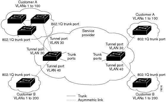
Business customers of service providers often have specific requirements for VLAN IDs and the number of VLANs to be supported. The VLAN ranges required by different customers in the same service-provider network might overlap, and traffic of customers through the infrastructure might be mixed. Assigning a unique range of VLAN IDs to each customer would restrict customer configurations and could easily exceed the VLAN limit (4096) of the IEEE 802.1Q specification.
Using the IEEE 802.1Q tunneling feature, service providers can use a single VLAN to support customers who have multiple VLANs. Customer VLAN IDs are preserved, and traffic from different customers is segregated within the service-provider network, even when they appear to be in the same VLAN. Using IEEE 802.1Q tunneling expands VLAN space by using a VLAN-in-VLAN hierarchy and retagging the tagged packets. A port configured to support IEEE 802.1Q tunneling is called a tunnel port. When you configure tunneling, you assign a tunnel port to a VLAN ID that is dedicated to tunneling. Each customer requires a separate service-provider VLAN ID, but that VLAN ID supports all of the customer’s VLANs.
Customer traffic tagged in the normal way with appropriate VLAN IDs comes from an IEEE 802.1Q trunk port on the customer device and into a tunnel port on the service-provider edge switch. The link between the customer device and the edge switch is asymmetric because one end is configured as an IEEE 802.1Q trunk port, and the other end is configured as a tunnel port. You assign the tunnel port interface to an access VLAN ID that is unique to each customer.
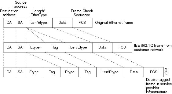
Packets coming from the customer trunk port into the tunnel port on the service-provider edge switch are normally IEEE 802.1Q-tagged with the appropriate VLAN ID. The tagged packets remain intact inside the switch and when they exit the trunk port into the service-provider network, they are encapsulated with another layer of an IEEE 802.1Q tag (called the metro tag) that contains the VLAN ID that is unique to the customer. The original customer IEEE 802.1Q tag is preserved in the encapsulated packet. Therefore, packets entering the service-provider network are double-tagged, with the outer (metro) tag containing the customer’s access VLAN ID, and the inner VLAN ID being that of the incoming traffic.
When the double-tagged packet enters another trunk port in a service-provider core switch, the outer tag is stripped as the switch processes the packet. When the packet exits another trunk port on the same core switch, the same metro tag is again added to the packet.
When the packet enters the trunk port of the service-provider egress switch, the outer tag is again stripped as the switch internally processes the packet. However, the metro tag is not added when the packet is sent out the tunnel port on the edge switch into the customer network. The packet is sent as a normal IEEE 802.1Q-tagged frame to preserve the original VLAN numbers in the customer network.
In the above network figure, Customer A was assigned VLAN 30, and Customer B was assigned VLAN 40. Packets entering the edge switch tunnel ports with IEEE 802.1Q tags are double-tagged when they enter the service-provider network, with the outer tag containing VLAN ID 30 or 40, appropriately, and the inner tag containing the original VLAN number, for example, VLAN 100. Even if both Customers A and B have VLAN 100 in their networks, the traffic remains segregated within the service-provider network because the outer tag is different. Each customer controls its own VLAN numbering space, which is independent of the VLAN numbering space used by other customers and the VLAN numbering space used by the service-provider network.
At the outbound tunnel port, the original VLAN numbers on the customer’s network are recovered. It is possible to have multiple levels of tunneling and tagging, but the switch supports only one level in this release.
If traffic coming from a customer network is not tagged (native VLAN frames), these packets are bridged or routed as normal packets. All packets entering the service-provider network through a tunnel port on an edge switch are treated as untagged packets, whether they are untagged or already tagged with IEEE 802.1Q headers. The packets are encapsulated with the metro tag VLAN ID (set to the access VLAN of the tunnel port) when they are sent through the service-provider network on an IEEE 802.1Q trunk port. The priority field on the metro tag is set to the interface class of service (CoS) priority configured on the tunnel port. (The default is zero if none is configured.)
On switches, because 802.1Q tunneling is configured on a per-port basis, it does not matter whether the switch is a standalone switch or a stack member. All configuration is done on the stack master.
IEEE 802.1Q Tunneling Configuration Guidelines
When you configure IEEE 802.1Q tunneling, you should always use an asymmetrical link between the customer device and the edge switch, with the customer device port configured as an IEEE 802.1Q trunk port and the edge switch port configured as a tunnel port.
Assign tunnel ports only to VLANs that are used for tunneling.
Configuration requirements for native VLANs and for and maximum transmission units (MTUs) are explained in these next sections.
Native VLANs
When configuring IEEE 802.1Q tunneling on an edge switch, you must use IEEE 802.1Q trunk ports for sending packets into the service-provider network. However, packets going through the core of the service-provider network can be carried through IEEE 802.1Q trunks, ISL trunks, or nontrunking links. When IEEE 802.1Q trunks are used in these core switches, the native VLANs of the IEEE 802.1Q trunks must not match any native VLAN of the nontrunking (tunneling) port on the same switch because traffic on the native VLAN would not be tagged on the IEEE 802.1Q sending trunk port.
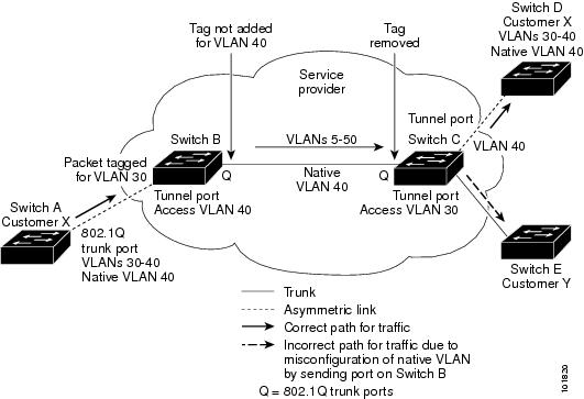
In the following network figure, VLAN 40 is configured as the native VLAN for the IEEE 802.1Q trunk port from Customer X at the ingress edge switch in the service-provider network (Switch B). Switch A of Customer X sends a tagged packet on VLAN 30 to the ingress tunnel port of Switch B in the service-provider network, which belongs to access VLAN 40. Because the access VLAN of the tunnel port (VLAN 40) is the same as the native VLAN of the edge switch trunk port (VLAN 40), the metro tag is not added to tagged packets received from the tunnel port. The packet carries only the VLAN 30 tag through the service-provider network to the trunk port of the egress-edgeswitch (Switch C) and is misdirected through the egress switch tunnel port to Customer Y.
-
Use the vlan dot1q tag native global configuration command to configure the edge switches so that all packets going out an IEEE 802.1Q trunk, including the native VLAN, are tagged. If the switches is configured to tag native VLAN packets on all IEEE 802.1Q trunks, the switches accepts untagged packets, but sends only tagged packets.
-
Ensure that the native VLAN ID on the edge switches trunk port is not within the customer VLAN range. For example, if the trunk port carries traffic of VLANs 100 to 200, assign the native VLAN a number outside that range.
System MTU
The default system MTU for traffic on the switch is 1500 bytes. You can configure Fast Ethernet ports on the switch members in the mixed hardware switch stack to support frames larger than 1500 bytes by using the system mtu global configuration command.
You can configure 10-Gigabit and Gigabit Ethernet ports to support frames larger than 1500 bytes by using the system mtu jumbo global configuration command.
The system MTU and system jumbo MTU values do not include the IEEE 802.1Q header. Because the IEEE 802.1Q tunneling feature increases the frame size by 4 bytes when the metro tag is added, you must configure all switches in the service-provider network to be able to process maximum frames by adding 4 bytes to the system MTU and system jumbo MTU sizes.
For example, the switch supports a maximum frame size of 1496 bytes with one of these configurations:
-
The switch has a system jumbo MTU value of 1500 bytes, and the switchport mode dot1q tunnel interface configuration command is configured on a 10-Gigabit or Gigabit Ethernet switch port.
-
The switch member has a system MTU value of 1500 bytes, and the switchport mode dot1q tunnel interface configuration command is configured on a Fast Ethernet port of the member.
Default IEEE 802.1Q Tunneling Configuration
By default, IEEE 802.1Q tunneling is disabled because the default switchport mode is dynamic auto. Tagging of IEEE 802.1Q native VLAN packets on all IEEE 802.1Q trunk ports is also disabled.
Layer 2 Protocol Tunneling Overview
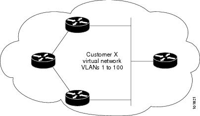
Customers at different sites connected across a service-provider network need to use various Layer 2 protocols to scale their topologies to include all remote sites, as well as the local sites. STP must run properly, and every VLAN should build a proper spanning tree that includes the local site and all remote sites across the service-provider network. Cisco Discovery Protocol (CDP) must discover neighboring Cisco devices from local and remote sites. VLAN Trunking Protocol (VTP) must provide consistent VLAN configuration throughout all sites in the customer network.
When protocol tunneling is enabled, edge switches on the inbound side of the service-provider network encapsulate Layer 2 protocol packets with a special MAC address and send them across the service-provider network. Core switches in the network do not process these packets but forward them as normal packets. Layer 2 protocol data units (PDUs) for CDP, STP, or VTP cross the service-provider network and are delivered to customer switches on the outbound side of the service-provider network. Identical packets are received by all customer ports on the same VLANs with these results:
-
Users on each of a customer’s sites can properly run STP, and every VLAN can build a correct spanning tree based on parameters from all sites and not just from the local site.
-
CDP discovers and shows information about the other Cisco devices connected through the service-provider network.
-
VTP provides consistent VLAN configuration throughout the customer network, propagating to all switches through the service provider.
 Note | To provide interoperability with third-party vendors, you can use the Layer 2 protocol-tunnel bypass feature. Bypass mode transparently forwards control PDUs to vendor switches that have different ways of controlling protocol tunneling. You implement bypass mode by enabling Layer 2 protocol tunneling on the egress trunk port. When Layer 2 protocol tunneling is enabled on the trunk port, the encapsulated tunnel MAC address is removed and the protocol packets have their normal MAC address. |
Layer 2 protocol tunneling can be used independently or can enhance IEEE 802.1Q tunneling. If protocol tunneling is not enabled on IEEE 802.1Q tunneling ports, remoteswitches at the receiving end of the service-provider network do not receive the PDUs and cannot properly run STP, CDP, and VTP. When protocol tunneling is enabled, Layer 2 protocols within each customer’s network are totally separate from those running within the service-provider network. Customer switches on different sites that send traffic through the service-provider network with IEEE 802.1Q tunneling achieve complete knowledge of the customer’s VLAN. If IEEE 802.1Q tunneling is not used, you can still enable Layer 2 protocol tunneling by connecting to the customer switch through access ports and by enabling tunneling on the service-provider access port.
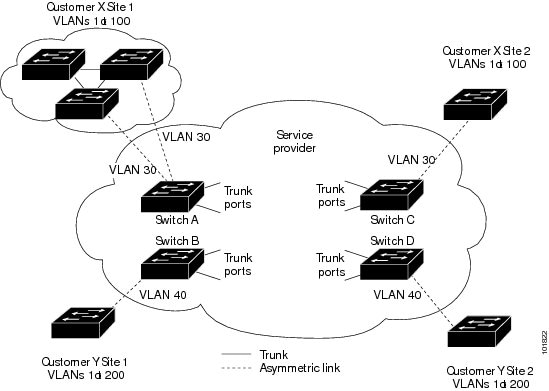
For example, in the following figure (Layer 2 Protocol Tunneling), Customer X has four switches in the same VLAN, that are connected through the service-provider network. If the network does not tunnel PDUs, switches on the far ends of the network cannot properly run STP, CDP, and VTP. For example, STP for a VLAN on a switch in Customer X, Site 1, will build a spanning tree on theswitches at that site without considering convergence parameters based on Customer X’s switch in Site 2. This could result in the topology shown in the Layer 2 Network Topology without Proper Convergence figure.
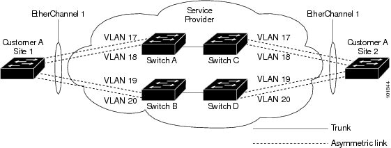
In an SP network, you can use Layer 2 protocol tunneling to enhance the creation of EtherChannels by emulating a point-to-point network topology. When you enable protocol tunneling (PAgP or LACP) on the SP switch, remote customer switches receive the PDUs and can negotiate the automatic creation of EtherChannels.
For example, in the following figure (Layer 2 Protocol Tunneling for EtherChannels), Customer A has two switches in the same VLAN that are connected through the SP network. When the network tunnels PDUs, switches on the far ends of the network can negotiate the automatic creation of EtherChannels without needing dedicated lines.
Layer 2 Protocol Tunneling on Ports
You can enable Layer 2 protocol tunneling (by protocol) on the ports that are connected to the customer in the edge switches of the service-provider network. The service-provider edge switches connected to the customer switch perform the tunneling process. Edge switch tunnel ports are connected to customer IEEE 802.1Q trunk ports. Edge switch access ports are connected to customer access ports. The edge switches connected to the customer switch perform the tunneling process.
You can enable Layer 2 protocol tunneling on ports that are configured as access ports or tunnel ports. You cannot enable Layer 2 protocol tunneling on ports configured in either switchport mode dynamic auto mode (the default mode) or switchport mode dynamic desirable mode.
The switch supports Layer 2 protocol tunneling for CDP, STP, and VTP. For emulated point-to-point network topologies, it also supports PAgP, LACP, and UDLD protocols. The switch does not support Layer 2 protocol tunneling for LLDP.
Note | PAgP, LACP, and UDLD protocol tunneling is only intended to emulate a point-to-point topology. An erroneous configuration that sends tunneled packets to many ports could lead to a network failure. |
When the Layer 2 PDUs that entered the service-provider inbound edge switch through a Layer 2 protocol-enabled port exit through the trunk port into the service-provider network, the switch overwrites the customer PDU-destination MAC address with a well-known Cisco proprietary multicast address (01-00-0c-cd-cd-d0). If IEEE 802.1Q tunneling is enabled, packets are also double-tagged; the outer tag is the customer metro tag, and the inner tag is the customer’s VLAN tag. The core switches ignore the inner tags and forward the packet to all trunk ports in the same metro VLAN. The edge switches on the outbound side restore the proper Layer 2 protocol and MAC address information and forward the packets to all tunnel or access ports in the same metro VLAN. Therefore, the Layer 2 PDUs remain intact and are delivered across the service-provider infrastructure to the other side of the customer network.
See the Layer 2 Protocol Tunneling figure in Layer 2 Protocol Tunneling Overview, with Customer X and Customer Y in access VLANs 30 and 40, respectively. Asymmetric links connect the customers in Site 1 to edge switches in the service-provider network. The Layer 2 PDUs (for example, BPDUs) coming into Switch B from Customer Y in Site 1 are forwarded to the infrastructure as double-tagged packets with the well-known MAC address as the destination MAC address. These double-tagged packets have the metro VLAN tag of 40, as well as an inner VLAN tag (for example, VLAN 100). When the double-tagged packets enter Switch D, the outer VLAN tag 40 is removed, the well-known MAC address is replaced with the respective Layer 2 protocol MAC address, and the packet is sent to Customer Y on Site 2 as a single-tagged frame in VLAN 100.
You can also enable Layer 2 protocol tunneling on access ports on the edge switch connected to access or trunk ports on the customer switch. In this case, the encapsulation and decapsulation process is the same as described in the previous paragraph, except that the packets are not double-tagged in the service-provider network. The single tag is the customer-specific access VLAN tag.
In switch stacks, Layer 2 protocol tunneling configuration is distributed among all stack members. Each stack member that receives an ingress packet on a local port encapsulates or decapsulates the packet and forwards it to the appropriate destination port. On a single switch, ingress Layer 2 protocol-tunneled traffic is sent across all local ports in the same VLAN on which Layer 2 protocol tunneling is enabled. In a stack, packets received by a Layer 2 protocol-tunneled port are distributed to all ports in the stack that are configured for Layer 2 protocol tunneling and are in the same VLAN. All Layer 2 protocol tunneling configuration is handled by the stack master and distributed to all stack members.
Default Layer 2 Protocol Tunneling Configuration
The following table shows the default Layer 2 protocol tunneling configuration.
Feature |
Default Setting |
|---|---|
Layer 2 protocol tunneling |
Disabled. |
Shutdown threshold |
None set. |
Drop threshold |
None set. |
CoS Value |
If a CoS value is configured on the interface, that value is used to set the BPDU CoS value for Layer 2 protocol tunneling. If no CoS value is configured at the interface level, the default value for CoS marking of L2 protocol tunneling BPDUs is 5. This does not apply to data traffic. |
How to Configure Tunneling
Configuring an IEEE 802.1Q Tunneling Port
Configuring Layer 2 Protocol Tunneling
| Command or Action | Purpose | |||||
|---|---|---|---|---|---|---|
| Step 1 |
enable
Example:
Switch> enable
|
Enables privileged EXEC mode. Enter your password if prompted. | ||||
| Step 2 | configure
terminal
Example: Switch# configure terminal | |||||
| Step 3 | interface
interface-id
Example: Switch(config)# interface gigabitethernet1/0/1 |
Specifies the interface connected to the phone, and enters interface configuration mode. | ||||
| Step 4 | Use one of the
following:
Example: Switch# switchport mode access Switch# switchport mode dot1q-tunnel |
Configures the interface as an access port or an IEEE 802.1Q tunnel port. | ||||
| Step 5 | l2protocol-tunnel [cdp |
lldp
|
point-to-point |
stp |
vtp]
Example:
Switch# l2protocol-tunnel cdp
|
Enables protocol tunneling for the desired protocol. If no keyword is entered, tunneling is enabled for all three Layer 2 protocols.
| ||||
| Step 6 | l2protocol-tunnel
shutdown-threshold [
packet_second_rate_value |
cdp |
lldp
point-to-point |
stp |
vtp]
Example:
Switch# l2protocol-tunnel shutdown-threshold 100 cdp
|
(Optional) Configures the threshold for packets-per-second accepted for encapsulation. The interface is disabled if the configured threshold is exceeded. If no protocol option is specified, the threshold applies to each of the tunneled Layer 2 protocol types. The range is 1 to 4096. The default is to have no threshold configured.
| ||||
| Step 7 | l2protocol-tunnel
drop-threshold [
packet_second_rate_value |
cdp |
lldp
|
point-to-point |
stp |
vtp]
Example:
Switch# l2protocol-tunnel drop-threshold 100 cdp
|
(Optional) Configures the threshold for packets-per-second accepted for encapsulation. The interface drops packets if the configured threshold is exceeded. If no protocol option is specified, the threshold applies to each of the tunneled Layer 2 protocol types. The range is 1 to 4096. The default is to have no threshold configured.
| ||||
| Step 8 | exit
Example:
Switch# exit
|
Returns to global configuration mode. | ||||
| Step 9 | errdisable recovery cause l2ptguard
Example:
Switch(config)# errdisable recovery cause l2ptguard
|
(Optional) Configures the recovery mechanism from a Layer 2 maximum-rate error so that the interface is reenabled and can try again. Errdisable recovery is disabled by default; when enabled, the default time interval is 300 seconds. | ||||
| Step 10 | l2protocol-tunnel cos
value
Example:
Switch(config)# l2protocol-tunnel cos value 7
|
(Optional) Configures the CoS value for all tunneled Layer 2 PDUs. The range is 0 to 7; the default is the default CoS value for the interface. If none is configured, the default is 5. | ||||
| Step 11 | end
Example: Switch(config)# end | |||||
| Step 12 | show l2protocol
Example:
Switch# show l2protocol
|
Displays the Layer 2 tunnel ports on the switch, including the protocols configured, the thresholds, and the counters. | ||||
| Step 13 | copy running-config
startup-config
Example:
Switch# copy running-config startup-config
|
(Optional) Saves your entries in the configuration file. |
Configuring the SP Edge Switch
| Command or Action | Purpose | |||||
|---|---|---|---|---|---|---|
| Step 1 |
enable
Example:
Switch> enable
|
Enables privileged EXEC mode. Enter your password if prompted. | ||||
| Step 2 | configure
terminal
Example: Switch# configure terminal | |||||
| Step 3 | interface
interface-id
Example: Switch(config)# interface gigabitethernet1/0/1 |
Specifies the interface connected to the phone, and enters interface configuration mode. | ||||
| Step 4 | switchport mode dot1q-tunnel
Example:
Switch(config-if)# switchport mode dot1q-tunnel
|
Configures the interface as an IEEE 802.1Q tunnel port. | ||||
| Step 5 | l2protocol-tunnel
point-to-point [pagp |
lacp |
udld]
Example:
Switch(config-if)# l2protocol-tunnel point-to-point pagp
|
(Optional) Enables point-to-point protocol tunneling for the desired protocol. If no keyword is entered, tunneling is enabled for all three protocols.
| ||||
| Step 6 | l2protocol-tunnel
shutdown-threshold [point-to-point [pagp |
lacp |
udld]]
value
Example:
Switch(config-if)# l2protocol-tunnel shutdown-threshold point-to-point pagp 100
|
(Optional) Configures the threshold for packets-per-second accepted for encapsulation. The interface is disabled if the configured threshold is exceeded. If no protocol option is specified, the threshold applies to each of the tunneled Layer 2 protocol types. The range is 1 to 4096. The default is to have no threshold configured.
| ||||
| Step 7 | l2protocol-tunnel
drop-threshold [point-to-point [pagp |
lacp |
udld]]
value
Example:
Switch(config-if)# l2protocol-tunnel drop-threshold point-to-point pagp 500
|
(Optional) Configures the threshold for packets-per-second accepted for encapsulation. The interface drops packets if the configured threshold is exceeded. If no protocol option is specified, the threshold applies to each of the tunneled Layer 2 protocol types. The range is 1 to 4096. The default is to have no threshold configured.
| ||||
| Step 8 | no cdp enable
Example:
Switch(config-if)# no cdp enable
|
Disables CDP on the interface. | ||||
| Step 9 | spanning-tree bpdu filter enable
Example:
Switch(config-if)# spanning-tree bpdu filter enable
|
Enables BPDU filtering on the interface. | ||||
| Step 10 | exit
Example:
Switch(config-if)# exit
|
Returns to global configuration mode. | ||||
| Step 11 | errdisable recovery cause l2ptguard
Example:
Switch(config)# errdisable recovery cause l2ptguard
|
(Optional) Configures the recovery mechanism from a Layer 2 maximum-rate error so that the interface is reenabled and can try again. Errdisable recovery is disabled by default; when enabled, the default time interval is 300 seconds. | ||||
| Step 12 | l2protocol-tunnel cos
value
Example:
Switch(config)# l2protocol-tunnel cos 2
|
(Optional) Configures the CoS value for all tunneled Layer 2 PDUs. The range is 0 to 7; the default is the default CoS value for the interface. If none is configured, the default is 5. | ||||
| Step 13 | end
Example: Switch(config)# end | |||||
| Step 14 | show l2protocol
Example:
Switch)# show l2protocol
|
Displays the Layer 2 tunnel ports on the switch, including the protocols configured, the thresholds, and the counters. | ||||
| Step 15 | copy running-config
startup-config
Example:
Switch# copy running-config startup-config
|
(Optional) Saves your entries in the configuration file. |
Configuring the Customer Switch
For EtherChannels, you need to configure both the SP edge switch and the customer switches for Layer 2 protocol tunneling.
| Command or Action | Purpose | |||
|---|---|---|---|---|
| Step 1 |
enable
Example:
Switch> enable
|
Enables privileged EXEC mode. Enter your password if prompted. | ||
| Step 2 | configure
terminal
Example: Switch# configure terminal | |||
| Step 3 | interface
interface-id
Example: Switch(config)# interface gigabitethernet1/0/1 |
Specifies the interface connected to the phone, and enters interface configuration mode. | ||
| Step 4 | switchport trunk encapsulation dot1q
Example:
Switch(config)# switchport trunk encapsulation dot1q
|
Sets the trunking encapsulation format to IEEE 802.1Q. | ||
| Step 5 | switchport mode trunk
Example:
Switch(config-if)# switchport mode trunk
|
Enables trunking on the interface. | ||
| Step 6 | udld port
Example:
Switch(config-if)# udld port
|
Enables UDLD in normal mode on the interface. | ||
| Step 7 | channel-group
channel-group-number mode desirable
Example:
Switch(config-if)# channel-group 25 mode desirable
|
Assigns the interface to a channel group, and specifies desirable for the PAgP mode. | ||
| Step 8 | exit
Example:
Switch(config-if)# exit
|
Returns to global configuration mode. | ||
| Step 9 | interface port-channel port-channel
number
Example:
Switch(config)# interface port-channel port-channel 25
|
Enters port-channel interface mode. | ||
| Step 10 | shutdown
Example:
Switch(config)# shutdown
|
Shuts down the interface. | ||
| Step 11 | no shutdown
Example:
Switch(config)# no shutdown
|
Enables the interface. | ||
| Step 12 | end
Example: Switch(config)# end | |||
| Step 13 | show l2protocol
Example:
Switch# show l2protocol
|
Displays the Layer 2 tunnel ports on the switch, including the protocols configured, the thresholds, and the counters. | ||
| Step 14 | copy
running-config startup-config
Example: Switch# copy running-config startup-config |
(Optional) Saves your entries in the configuration file.
|
Configuration Examples for IEEE 802.1Q and Layer 2 Protocol Tunneling
Example: Configuring an IEEE 802.1Q Tunneling Port
The following example shows how to configure an interface as a tunnel port, enable tagging of native VLAN packets, and verify the configuration. In this configuration, the VLAN ID for the customer connected to Gigabit Ethernet interface 7 on stack member 1 is VLAN 22.
Switch(config)# interface gigabitethernet1/0/7
Switch(config-if)# switchport access vlan 22
% Access VLAN does not exist. Creating vlan 22
Switch(config-if)# switchport mode dot1q-tunnel
Switch(config-if)# exit
Switch(config)# vlan dot1q tag native
Switch(config)# end
Switch# show dot1q-tunnel interface gigabitethernet1/0/7
Port
-----
Gi1/0/1Port
-----
Switch# show vlan dot1q tag native
dot1q native vlan tagging is enabled
Example: Configuring Layer 2 Protocol Tunneling
The following example shows how to configure Layer 2 protocol tunneling for CDP, STP, and VTP and to verify the configuration.
Switch(config)# interface gigabitethernet1/0/11
Switch(config-if)# l2protocol-tunnel cdp
Switch(config-if)# l2protocol-tunnel stp
Switch(config-if)# l2protocol-tunnel vtp
Switch(config-if)# l2protocol-tunnel shutdown-threshold 1500
Switch(config-if)# l2protocol-tunnel drop-threshold 1000
Switch(config-if)# exit
Switch(config)# l2protocol-tunnel cos 7
Switch(config)# end
Switch# show l2protocol

COS for Encapsulated Packets: 7
Port Protocol Shutdown Drop Encapsulation Decapsulation Drop
Threshold Threshold Counter Counter Counter
------- -------- --------- --------- ------------- ------------- -------------
Gi0/11 cdp 1500 1000 2288 2282 0
stp 1500 1000 116 13 0
vtp 1500 1000 3 67 0
pagp ---- ---- 0 0 0
lacp ---- ---- 0 0 0
udld ---- ---- 0 0 0
Examples: Configuring the SP Edge and Customer Switches
This example shows how to configure the SP edge switch 1 and edge switch 2. VLANs 17, 18, 19, and 20 are the access VLANs, Fast Ethernet interfaces 1 and 2 are point-to-point tunnel ports with PAgP and UDLD enabled, the drop threshold is 1000, and Fast Ethernet interface 3 is a trunk port.
SP edge switch 1 configuration:
Switch(config)# interface gigabitethernet1/0/1
Switch(config-if)# switchport access vlan 17
Switch(config-if)# switchport mode dot1q-tunnel
Switch(config-if)# l2protocol-tunnel point-to-point pagp
Switch(config-if)# l2protocol-tunnel point-to-point udld
Switch(config-if)# l2protocol-tunnel drop-threshold point-to-point pagp 1000
Switch(config-if)# exit
Switch(config)# interface gigabitethernet1/0/2
Switch(config-if)# switchport access vlan 18
Switch(config-if)# switchport mode dot1q-tunnel
Switch(config-if)# l2protocol-tunnel point-to-point pagp
Switch(config-if)# l2protocol-tunnel point-to-point udld
Switch(config-if)# l2protocol-tunnel drop-threshold point-to-point pagp 1000
Switch(config-if)# exit
Switch(config)# interface gigabitethernet1/0/3
Switch(config-if)# switchport trunk encapsulation isl
Switch(config-if)# switchport mode trunk
SP edge switch 2 configuration:
Switch(config)# interface gigabitethernet1/0/1
Switch(config-if)# switchport access vlan 19
Switch(config-if)# switchport mode dot1q-tunnel
Switch(config-if)# l2protocol-tunnel point-to-point pagp
Switch(config-if)# l2protocol-tunnel point-to-point udld
Switch(config-if)# l2protocol-tunnel drop-threshold point-to-point pagp 1000
Switch(config-if)# exit
Switch(config)# interface gigabitethernet1/0/2
Switch(config-if)# switchport access vlan 20
Switch(config-if)# switchport mode dot1q-tunnel
Switch(config-if)# l2protocol-tunnel point-to-point pagp
Switch(config-if)# l2protocol-tunnel point-to-point udld
Switch(config-if)# l2protocol-tunnel drop-threshold point-to-point pagp 1000
Switch(config-if)# exit
Switch(config)# interface gigabitethernet1/0/3
Switch(config-if)# switchport trunk encapsulation isl
Switch(config-if)# switchport mode trunk
This example shows how to configure the customer switch at Site 1. Fast Ethernet interfaces 1, 2, 3, and 4 are set for IEEE 802.1Q trunking, UDLD is enabled, EtherChannel group 1 is enabled, and the port channel is shut down and then enabled to activate the EtherChannel configuration.
Switch(config)# interface gigabitethernet1/0/1
Switch(config-if)# switchport trunk encapsulation dot1q
Switch(config-if)# switchport mode trunk
Switch(config-if)# udld enable
Switch(config-if)# channel-group 1 mode desirable
Switch(config-if)# exit
Switch(config)# interface gigabitethernet1/0/2
Switch(config-if)# switchport trunk encapsulation dot1q
Switch(config-if)# switchport mode trunk
Switch(config-if)# udld enable
Switch(config-if)# channel-group 1 mode desirable
Switch(config-if)# exit
Switch(config)# interface gigabitethernet1/0/3
Switch(config-if)# switchport trunk encapsulation dot1q
Switch(config-if)# switchport mode trunk
Switch(config-if)# udld enable
Switch(config-if)# channel-group 1 mode desirable
Switch(config-if)# exit
Switch(config)# interface gigabitethernet1/0/4
Switch(config-if)# switchport trunk encapsulation dot1q
Switch(config-if)# switchport mode trunk
Switch(config-if)# udld enable
Switch(config-if)# channel-group 1 mode desirable
Switch(config-if)# exit
Switch(config)# interface port-channel 1
Switch(config-if)# shutdown
Switch(config-if)# no shutdown
Switch(config-if)# exit
Monitoring Tunneling Status
The following table describes the commands used to monitor tunneling status.
|
Command |
Purpose |
|---|---|
|
clear l2protocol-tunnel counters |
Clears the protocol counters on Layer 2 protocol tunneling ports. |
|
show dot1q-tunnel |
Displays IEEE 802.1Q tunnel ports on the switch. |
|
show dot1q-tunnel interface interface-id |
Verifies if a specific interface is a tunnel port. |
|
show l2protocol-tunnel |
Displays information about Layer 2 protocol tunneling ports. |
|
show errdisable recovery |
Verifies if the recovery timer from a Layer 2 protocol-tunnel error disable state is enabled. |
|
show l2protocol-tunnel interface interface-id |
Displays information about a specific Layer 2 protocol tunneling port. |
|
show l2protocol-tunnel summary |
Displays only Layer 2 protocol summary information. |
|
show vlan dot1q tag native |
Displays the status of native VLAN tagging on the switch. |
Where to Go Next
You can configure the following:
Additional References
Related Documents
| Related Topic | Document Title |
|---|---|
For complete syntax and usage information for the commands used in this chapter. |
Standards and RFCs
| Standard/RFC | Title |
|---|---|
— |
— |
MIBs
| MIB | MIBs Link |
|---|---|
All supported MIBs for this release. |
To locate and download MIBs for selected platforms, Cisco IOS releases, and feature sets, use Cisco MIB Locator found at the following URL: |
Technical Assistance
| Description | Link |
|---|---|
|
The Cisco Support website provides extensive online resources, including documentation and tools for troubleshooting and resolving technical issues with Cisco products and technologies. To receive security and technical information about your products, you can subscribe to various services, such as the Product Alert Tool (accessed from Field Notices), the Cisco Technical Services Newsletter, and Really Simple Syndication (RSS) Feeds. Access to most tools on the Cisco Support website requires a Cisco.com user ID and password. |
Feature History and Information for Tunneling
| Release | Modification |
|---|---|
| Cisco IOS 15.0(2)EX1 |
This feature was introduced. |
 Feedback