- Index
- Preface
- Overview
- Using the Command-Line Interface
- Assigning the Switch IP Address and Default Gateway
- Configuring Cisco IOS CNS Agents
- Clustering Switches
- Administering the Switch
- Configuring SDM Templates
- Configuring Switch-Based Authentication
- Configuring IEEE 802.1x Port-Based Authentication
- Configuring Interface Characteristics
- Configuring Smartports Macros
- Configuring VLANs
- Configuring VTP
- Configuring Voice VLAN
- Configuring STP
- Configuring MSTP
- Configuring Optional Spanning-Tree Features
- Configuring IGMP Snooping and MVR
- Configuring Port-Based Traffic Control
- Configuring CDP
- Configuring LLDP
- Configuring UDLD
- Configuring SPAN
- Configuring RMON
- Configuring System Message Logging
- Configuring SNMP
- Configuring QoS
- Configuring EtherChannels
- Troubleshooting
- Supported MIBs
- Working with the Cisco IOS File System, Configuration Files, and Software Images
- Recommendations for Upgrading a Catalyst 2950 Switch to a Catalyst 2960 Switch
- Unsupported Commands in Cisco IOS Release 12.2(37)EY
Catalyst 2960 Switch Software Configuration Guide (LAN Lite Image), Rel 12.2(37)EY
Bias-Free Language
The documentation set for this product strives to use bias-free language. For the purposes of this documentation set, bias-free is defined as language that does not imply discrimination based on age, disability, gender, racial identity, ethnic identity, sexual orientation, socioeconomic status, and intersectionality. Exceptions may be present in the documentation due to language that is hardcoded in the user interfaces of the product software, language used based on RFP documentation, or language that is used by a referenced third-party product. Learn more about how Cisco is using Inclusive Language.
- Updated:
- August 6, 2007
Chapter: Overview
Overview
This chapter provides these topics about the Catalyst 2960 switch LAN Lite software:
•![]() Default Settings After Initial Switch Configuration
Default Settings After Initial Switch Configuration
•![]() Network Configuration Examples
Network Configuration Examples
In this document, IP refers to IP Version 4 (IPv4).
Features
Some features described in this chapter are available only on the cryptographic (supports encryption) version of the software. You must obtain authorization to use this feature and to download the cryptographic version of the software from Cisco.com. For more information, see the release notes for this release.
The switch has these features:
•![]() Ease-of-Deployment and Ease-of-Use Features
Ease-of-Deployment and Ease-of-Use Features
•![]() Manageability Features (includes a feature requiring the cryptographic version of the software)
Manageability Features (includes a feature requiring the cryptographic version of the software)
•![]() Availability and Redundancy Features
Availability and Redundancy Features
•![]() Security Features (includes a feature requiring the cryptographic version of the software)
Security Features (includes a feature requiring the cryptographic version of the software)
Ease-of-Deployment and Ease-of-Use Features
The switch ships with these features to make the deployment and the use easier:
•![]() Express Setup for quickly configuring a switch for the first time with basic IP information, contact information, switch and Telnet passwords, and Simple Network Management Protocol (SNMP) information through a browser-based program. For more information about Express Setup, see the getting started guide.
Express Setup for quickly configuring a switch for the first time with basic IP information, contact information, switch and Telnet passwords, and Simple Network Management Protocol (SNMP) information through a browser-based program. For more information about Express Setup, see the getting started guide.
•![]() User-defined and Cisco-default Smartports macros for creating custom switch configurations for simplified deployment across the network.
User-defined and Cisco-default Smartports macros for creating custom switch configurations for simplified deployment across the network.
•![]() An embedded device manager GUI for configuring and monitoring a single switch through a web browser. For information about launching the device manager, see the getting started guide. For more information about the device manager, see the switch online help.
An embedded device manager GUI for configuring and monitoring a single switch through a web browser. For information about launching the device manager, see the getting started guide. For more information about the device manager, see the switch online help.
•![]() Cisco Network Assistant (hereafter referred to as Network Assistant) for
Cisco Network Assistant (hereafter referred to as Network Assistant) for
–![]() Managing communities, which are device groups like clusters, except that they can contain routers and access points and can be made more secure.
Managing communities, which are device groups like clusters, except that they can contain routers and access points and can be made more secure.
–![]() Simplifying and minimizing switch and switch cluster management from anywhere in your intranet.
Simplifying and minimizing switch and switch cluster management from anywhere in your intranet.
–![]() Accomplishing multiple configuration tasks from a single graphical interface without needing to remember command-line interface (CLI) commands to accomplish specific tasks.
Accomplishing multiple configuration tasks from a single graphical interface without needing to remember command-line interface (CLI) commands to accomplish specific tasks.
–![]() Interactive guide mode that guides you in configuring complex features such as VLANs and quality of service (QoS).
Interactive guide mode that guides you in configuring complex features such as VLANs and quality of service (QoS).
–![]() Configuration wizards that prompt you to provide only the minimum required information to configure complex features such as QoS priorities for video traffic, priority levels for data applications, and security.
Configuration wizards that prompt you to provide only the minimum required information to configure complex features such as QoS priorities for video traffic, priority levels for data applications, and security.
–![]() Downloading an image to a switch.
Downloading an image to a switch.
–![]() Applying actions to multiple ports and multiple switches at the same time, such as VLAN and QoS settings, inventory and statistic reports, link- and switch-level monitoring and troubleshooting, and multiple switch software upgrades.
Applying actions to multiple ports and multiple switches at the same time, such as VLAN and QoS settings, inventory and statistic reports, link- and switch-level monitoring and troubleshooting, and multiple switch software upgrades.
–![]() Viewing a topology of interconnected devices to identify existing switch clusters and eligible switches that can join a cluster and to identify link information between switches.
Viewing a topology of interconnected devices to identify existing switch clusters and eligible switches that can join a cluster and to identify link information between switches.
–![]() Monitoring real-time status of a switch or multiple switches from the LEDs on the front-panel images. The system and port LED colors on the images are similar to those used on the physical LEDs.
Monitoring real-time status of a switch or multiple switches from the LEDs on the front-panel images. The system and port LED colors on the images are similar to those used on the physical LEDs.

Note ![]() The CNA must be downloaded at this URL cisco.com/go/cna.
The CNA must be downloaded at this URL cisco.com/go/cna.
•![]() Switch clustering technology for
Switch clustering technology for
–![]() Unified configuration, monitoring, authentication, and software upgrade of multiple, cluster-capable switches, regardless of their geographic proximity and interconnection media, including Ethernet, Fast Ethernet, Fast EtherChannel, small form-factor pluggable (SFP) modules, Gigabit Ethernet, and Gigabit EtherChannel connections. For a list of cluster-capable switches, see the release notes.
Unified configuration, monitoring, authentication, and software upgrade of multiple, cluster-capable switches, regardless of their geographic proximity and interconnection media, including Ethernet, Fast Ethernet, Fast EtherChannel, small form-factor pluggable (SFP) modules, Gigabit Ethernet, and Gigabit EtherChannel connections. For a list of cluster-capable switches, see the release notes.
–![]() Automatic discovery of candidate switches and creation of clusters of up to 16 switches that can be managed through a single IP address.
Automatic discovery of candidate switches and creation of clusters of up to 16 switches that can be managed through a single IP address.
–![]() Extended discovery of cluster candidates that are not directly connected to the command switch.
Extended discovery of cluster candidates that are not directly connected to the command switch.
Performance Features
The switch ships with these performance features:
•![]() Autosensing of port speed and autonegotiation of duplex mode on all switch ports for optimizing bandwidth
Autosensing of port speed and autonegotiation of duplex mode on all switch ports for optimizing bandwidth
•![]() Automatic-medium-dependent interface crossover (auto-MDIX) capability on 10/100 and 10/100/1000 Mb/s interfaces and on 10/100/1000 BASE-TX SFP module interfaces that enables the interface to automatically detect the required cable connection type (straight-through or crossover) and to configure the connection appropriately
Automatic-medium-dependent interface crossover (auto-MDIX) capability on 10/100 and 10/100/1000 Mb/s interfaces and on 10/100/1000 BASE-TX SFP module interfaces that enables the interface to automatically detect the required cable connection type (straight-through or crossover) and to configure the connection appropriately
•![]() Support for up to 9000 bytes for frames that are bridged in hardware, and up to 2000 bytes for frames that are bridged by software
Support for up to 9000 bytes for frames that are bridged in hardware, and up to 2000 bytes for frames that are bridged by software
•![]() IEEE 802.3x flow control on all ports (the switch does not send pause frames)
IEEE 802.3x flow control on all ports (the switch does not send pause frames)
•![]() EtherChannel for enhanced fault tolerance and for providing up to 8 Gb/s (Gigabit EtherChannel) or 800 Mb/s (Fast EtherChannel) full-duplex bandwidth among switches, routers, and servers
EtherChannel for enhanced fault tolerance and for providing up to 8 Gb/s (Gigabit EtherChannel) or 800 Mb/s (Fast EtherChannel) full-duplex bandwidth among switches, routers, and servers
•![]() Port Aggregation Protocol (PAgP) and Link Aggregation Control Protocol (LACP) for automatic creation of EtherChannel links
Port Aggregation Protocol (PAgP) and Link Aggregation Control Protocol (LACP) for automatic creation of EtherChannel links
•![]() Forwarding of Layer 2 packets at Gigabit line rate
Forwarding of Layer 2 packets at Gigabit line rate
•![]() Per-port storm control for preventing broadcast, multicast, and unicast storms
Per-port storm control for preventing broadcast, multicast, and unicast storms
•![]() Port blocking on forwarding unknown Layer 2 unknown unicast, multicast, and bridged broadcast traffic
Port blocking on forwarding unknown Layer 2 unknown unicast, multicast, and bridged broadcast traffic
•![]() Internet Group Management Protocol (IGMP) snooping for IGMP Versions 1, 2, and 3 for efficiently forwarding multimedia and multicast traffic
Internet Group Management Protocol (IGMP) snooping for IGMP Versions 1, 2, and 3 for efficiently forwarding multimedia and multicast traffic
•![]() IGMP report suppression for sending only one IGMP report per multicast router query to the multicast devices (supported only for IGMPv1 or IGMPv2 queries)
IGMP report suppression for sending only one IGMP report per multicast router query to the multicast devices (supported only for IGMPv1 or IGMPv2 queries)
•![]() IGMP snooping querier support to configure switch to generate periodic IGMP general query messages
IGMP snooping querier support to configure switch to generate periodic IGMP general query messages
•![]() IGMP filtering for controlling the set of multicast groups to which hosts on a switch port can belong
IGMP filtering for controlling the set of multicast groups to which hosts on a switch port can belong
•![]() IGMP throttling for configuring the action when the maximum number of entries is in the IGMP forwarding table
IGMP throttling for configuring the action when the maximum number of entries is in the IGMP forwarding table
•![]() IGMP leave timer for configuring the leave latency for the network
IGMP leave timer for configuring the leave latency for the network
•![]() Switch Database Management (SDM) templates for allocating system resources to maximize support for user-selected features
Switch Database Management (SDM) templates for allocating system resources to maximize support for user-selected features
Management Options
These are the options for configuring and managing the switch:
•![]() An embedded device manager—The device manager is a GUI that is integrated in the software image. You use it to configure and to monitor a single switch. For information about launching the device manager, see the getting started guide. For more information about the device manager, see the switch online help.
An embedded device manager—The device manager is a GUI that is integrated in the software image. You use it to configure and to monitor a single switch. For information about launching the device manager, see the getting started guide. For more information about the device manager, see the switch online help.
•![]() Network Assistant—Network Assistant is a network management application that can be downloaded from Cisco.com. You use it to manage a single switch, a cluster of switches, or a community of devices. For more information about Network Assistant, see Getting Started with Cisco Network Assistant, available on Cisco.com.
Network Assistant—Network Assistant is a network management application that can be downloaded from Cisco.com. You use it to manage a single switch, a cluster of switches, or a community of devices. For more information about Network Assistant, see Getting Started with Cisco Network Assistant, available on Cisco.com.
•![]() CLI—The Cisco IOS software supports desktop- and multilayer-switching features. You can access the CLI either by connecting your management station directly to the switch console port or by using Telnet from a remote management station. For more information about the CLI, see "Using the Command-Line Interface."
CLI—The Cisco IOS software supports desktop- and multilayer-switching features. You can access the CLI either by connecting your management station directly to the switch console port or by using Telnet from a remote management station. For more information about the CLI, see "Using the Command-Line Interface."
•![]() SNMP—SNMP management applications such as CiscoWorks2000 LAN Management Suite (LMS) and HP OpenView. You can manage from an SNMP-compatible management station that is running platforms such as HP OpenView or SunNet Manager. The switch supports a comprehensive set of MIB extensions and four remote monitoring (RMON) groups. For more information about using SNMP, see Chapter 26, "Configuring SNMP."
SNMP—SNMP management applications such as CiscoWorks2000 LAN Management Suite (LMS) and HP OpenView. You can manage from an SNMP-compatible management station that is running platforms such as HP OpenView or SunNet Manager. The switch supports a comprehensive set of MIB extensions and four remote monitoring (RMON) groups. For more information about using SNMP, see Chapter 26, "Configuring SNMP."
•![]() CNS—Cisco Networking Services is network management software that acts as a configuration service for automating the deployment and management of network devices and services. You can automate initial configurations and configuration updates by generating switch-specific configuration changes, sending them to the switch, executing the configuration change, and logging the results.
CNS—Cisco Networking Services is network management software that acts as a configuration service for automating the deployment and management of network devices and services. You can automate initial configurations and configuration updates by generating switch-specific configuration changes, sending them to the switch, executing the configuration change, and logging the results.
For more information about CNS, see "Configuring Cisco IOS CNS Agents."
Manageability Features
These are the manageability features:
•![]() CNS embedded agents for automating switch management, configuration storage, and delivery
CNS embedded agents for automating switch management, configuration storage, and delivery
•![]() DHCP for automating configuration of switch information (such as IP address, default gateway, hostname, and Domain Name System [DNS] and TFTP server names)
DHCP for automating configuration of switch information (such as IP address, default gateway, hostname, and Domain Name System [DNS] and TFTP server names)
•![]() DHCP relay for forwarding User Datagram Protocol (UDP) broadcasts, including IP address requests, from DHCP clients
DHCP relay for forwarding User Datagram Protocol (UDP) broadcasts, including IP address requests, from DHCP clients
•![]() DHCP server for automatic assignment of IP addresses and other DHCP options to IP hosts
DHCP server for automatic assignment of IP addresses and other DHCP options to IP hosts
•![]() Directed unicast requests to a DNS server for identifying a switch through its IP address and its corresponding hostname and to a TFTP server for administering software upgrades from a TFTP server
Directed unicast requests to a DNS server for identifying a switch through its IP address and its corresponding hostname and to a TFTP server for administering software upgrades from a TFTP server
•![]() Address Resolution Protocol (ARP) for identifying a switch through its IP address and its corresponding MAC address
Address Resolution Protocol (ARP) for identifying a switch through its IP address and its corresponding MAC address
•![]() Unicast MAC address filtering to drop packets with specific source or destination MAC addresses
Unicast MAC address filtering to drop packets with specific source or destination MAC addresses
•![]() Cisco Discovery Protocol (CDP) Versions 1 and 2 for network topology discovery and mapping between the switch and other Cisco devices on the network
Cisco Discovery Protocol (CDP) Versions 1 and 2 for network topology discovery and mapping between the switch and other Cisco devices on the network
•![]() Link Layer Discovery Protocol (LLDP) for interoperability with third-party IP phones
Link Layer Discovery Protocol (LLDP) for interoperability with third-party IP phones
•![]() Network Time Protocol (NTP) for providing a consistent time stamp to all switches from an external source
Network Time Protocol (NTP) for providing a consistent time stamp to all switches from an external source
•![]() Cisco IOS File System (IFS) for providing a single interface to all file systems that the switch uses
Cisco IOS File System (IFS) for providing a single interface to all file systems that the switch uses
•![]() Configuration logging to log and to view changes to the switch configuration
Configuration logging to log and to view changes to the switch configuration
•![]() Unique device identifier to provide product identification information through a show inventory user EXEC command display
Unique device identifier to provide product identification information through a show inventory user EXEC command display
•![]() In-band management access through the device manager over a Netscape Navigator or Microsoft Internet Explorer browser session
In-band management access through the device manager over a Netscape Navigator or Microsoft Internet Explorer browser session
•![]() In-band management access for up to 16 simultaneous Telnet connections for multiple CLI-based sessions over the network
In-band management access for up to 16 simultaneous Telnet connections for multiple CLI-based sessions over the network
•![]() In-band management access for up to five simultaneous, encrypted Secure Shell (SSH) connections for multiple CLI-based sessions over the network (requires the cryptographic version of the software)
In-band management access for up to five simultaneous, encrypted Secure Shell (SSH) connections for multiple CLI-based sessions over the network (requires the cryptographic version of the software)
•![]() In-band management access through SNMP Versions 1, 2c, and 3 get and set requests
In-band management access through SNMP Versions 1, 2c, and 3 get and set requests
•![]() Out-of-band management access through the switch console port to a directly attached terminal or to a remote terminal through a serial connection or a modem
Out-of-band management access through the switch console port to a directly attached terminal or to a remote terminal through a serial connection or a modem
•![]() Secure Copy Protocol (SCP) feature to provide a secure and authenticated method for copying switch configuration or switch image files (requires the cryptographic version of the software)
Secure Copy Protocol (SCP) feature to provide a secure and authenticated method for copying switch configuration or switch image files (requires the cryptographic version of the software)
Availability and Redundancy Features
These are the availability and redundancy features:
•![]() UniDirectional Link Detection (UDLD) and aggressive UDLD for detecting and disabling unidirectional links on fiber-optic interfaces caused by incorrect fiber-optic wiring or port faults
UniDirectional Link Detection (UDLD) and aggressive UDLD for detecting and disabling unidirectional links on fiber-optic interfaces caused by incorrect fiber-optic wiring or port faults
•![]() IEEE 802.1D Spanning Tree Protocol (STP) for redundant backbone connections and loop-free networks. STP has these features:
IEEE 802.1D Spanning Tree Protocol (STP) for redundant backbone connections and loop-free networks. STP has these features:
–![]() Up to 64 spanning-tree instances supported
Up to 64 spanning-tree instances supported
–![]() Per-VLAN spanning-tree plus (PVST+) for load balancing across VLANs
Per-VLAN spanning-tree plus (PVST+) for load balancing across VLANs
–![]() Rapid PVST+ for load balancing across VLANs and providing rapid convergence of spanning-tree instances
Rapid PVST+ for load balancing across VLANs and providing rapid convergence of spanning-tree instances
–![]() UplinkFast and BackboneFast for fast convergence after a spanning-tree topology change and for achieving load balancing between redundant uplinks, including Gigabit uplinks
UplinkFast and BackboneFast for fast convergence after a spanning-tree topology change and for achieving load balancing between redundant uplinks, including Gigabit uplinks
•![]() IEEE 802.1s Multiple Spanning Tree Protocol (MSTP) for grouping VLANs into a spanning-tree instance and for providing multiple forwarding paths for data traffic and load balancing and rapid per-VLAN Spanning-Tree plus (rapid-PVST+) based on the IEEE 802.1w Rapid Spanning Tree Protocol (RSTP) for rapid convergence of the spanning tree by immediately changing root and designated ports to the forwarding state
IEEE 802.1s Multiple Spanning Tree Protocol (MSTP) for grouping VLANs into a spanning-tree instance and for providing multiple forwarding paths for data traffic and load balancing and rapid per-VLAN Spanning-Tree plus (rapid-PVST+) based on the IEEE 802.1w Rapid Spanning Tree Protocol (RSTP) for rapid convergence of the spanning tree by immediately changing root and designated ports to the forwarding state
•![]() Optional spanning-tree features available in PVST+, rapid-PVST+, and MSTP mode:
Optional spanning-tree features available in PVST+, rapid-PVST+, and MSTP mode:
–![]() Port Fast for eliminating the forwarding delay by enabling a port to immediately change from the blocking state to the forwarding state
Port Fast for eliminating the forwarding delay by enabling a port to immediately change from the blocking state to the forwarding state
–![]() BPDU guard for shutting down Port Fast-enabled ports that receive bridge protocol data units (BPDUs)
BPDU guard for shutting down Port Fast-enabled ports that receive bridge protocol data units (BPDUs)
–![]() BPDU filtering for preventing a Port Fast-enabled port from sending or receiving BPDUs
BPDU filtering for preventing a Port Fast-enabled port from sending or receiving BPDUs
–![]() Root guard for preventing switches outside the network core from becoming the spanning-tree root
Root guard for preventing switches outside the network core from becoming the spanning-tree root
–![]() Loop guard for preventing alternate or root ports from becoming designated ports because of a failure that leads to a unidirectional link
Loop guard for preventing alternate or root ports from becoming designated ports because of a failure that leads to a unidirectional link
VLAN Features
These are the VLAN features:
•![]() Support for up to 64 VLANs for assigning users to VLANs associated with appropriate network resources, traffic patterns, and bandwidth
Support for up to 64 VLANs for assigning users to VLANs associated with appropriate network resources, traffic patterns, and bandwidth
•![]() Support for VLAN IDs in the 1 to 4094 range as allowed by the IEEE 802.1Q standard
Support for VLAN IDs in the 1 to 4094 range as allowed by the IEEE 802.1Q standard
•![]() VLAN Query Protocol (VQP) for dynamic VLAN membership
VLAN Query Protocol (VQP) for dynamic VLAN membership
•![]() IEEE 802.1Q trunking encapsulation on all ports for network moves, adds, and changes; management and control of broadcast and multicast traffic; and network security by establishing VLAN groups for high-security users and network resources
IEEE 802.1Q trunking encapsulation on all ports for network moves, adds, and changes; management and control of broadcast and multicast traffic; and network security by establishing VLAN groups for high-security users and network resources
•![]() Dynamic Trunking Protocol (DTP) for negotiating trunking on a link between two devices and for negotiating the type of trunking encapsulation (IEEE 802.1Q) to be used
Dynamic Trunking Protocol (DTP) for negotiating trunking on a link between two devices and for negotiating the type of trunking encapsulation (IEEE 802.1Q) to be used
•![]() VLAN Trunking Protocol (VTP) and VTP pruning for reducing network traffic by restricting flooded traffic to links destined for stations receiving the traffic
VLAN Trunking Protocol (VTP) and VTP pruning for reducing network traffic by restricting flooded traffic to links destined for stations receiving the traffic
•![]() Voice VLAN for creating subnets for voice traffic from Cisco IP Phones
Voice VLAN for creating subnets for voice traffic from Cisco IP Phones
•![]() VLAN 1 minimization for reducing the risk of spanning-tree loops or storms by allowing VLAN 1 to be disabled on any individual VLAN trunk link. With this feature enabled, no user traffic is sent or received on the trunk. The switch CPU continues to send and receive control protocol frames.
VLAN 1 minimization for reducing the risk of spanning-tree loops or storms by allowing VLAN 1 to be disabled on any individual VLAN trunk link. With this feature enabled, no user traffic is sent or received on the trunk. The switch CPU continues to send and receive control protocol frames.
•![]() Port security on a PVLAN host to limit the number of MAC addresses learned on a port, or define which MAC addresses may be learned on a port
Port security on a PVLAN host to limit the number of MAC addresses learned on a port, or define which MAC addresses may be learned on a port
Security Features
The switch ships with these security features:
•![]() Password-protected access (read-only and read-write access) to management interfaces (device manager, Network Assistant, and the CLI) for protection against unauthorized configuration changes
Password-protected access (read-only and read-write access) to management interfaces (device manager, Network Assistant, and the CLI) for protection against unauthorized configuration changes
•![]() Multilevel security for a choice of security level, notification, and resulting actions
Multilevel security for a choice of security level, notification, and resulting actions
•![]() Static MAC addressing for ensuring security
Static MAC addressing for ensuring security
•![]() Protected port option for restricting the forwarding of traffic to designated ports on the same switch
Protected port option for restricting the forwarding of traffic to designated ports on the same switch
•![]() Port security option for limiting and identifying MAC addresses of the stations allowed to access the port
Port security option for limiting and identifying MAC addresses of the stations allowed to access the port
•![]() VLAN aware port security option to shut down the VLAN on the port when a violation occurs, instead of shutting down the entire port.
VLAN aware port security option to shut down the VLAN on the port when a violation occurs, instead of shutting down the entire port.
•![]() Port security aging to set the aging time for secure addresses on a port
Port security aging to set the aging time for secure addresses on a port
•![]() BPDU guard for shutting down a Port Fast-configured port when an invalid configuration occurs
BPDU guard for shutting down a Port Fast-configured port when an invalid configuration occurs
•![]() IEEE 802.1x port-based authentication to prevent unauthorized devices (clients) from gaining access to the network. These features are supported:
IEEE 802.1x port-based authentication to prevent unauthorized devices (clients) from gaining access to the network. These features are supported:
–![]() VLAN assignment for restricting IEEE 802.1x-authenticated users to a specified VLAN
VLAN assignment for restricting IEEE 802.1x-authenticated users to a specified VLAN
–![]() Port security for controlling access to IEEE 802.1x ports
Port security for controlling access to IEEE 802.1x ports
–![]() Voice VLAN to permit a Cisco IP Phone to access the voice VLAN regardless of the authorized or unauthorized state of the port
Voice VLAN to permit a Cisco IP Phone to access the voice VLAN regardless of the authorized or unauthorized state of the port
–![]() IP phone detection enhancement to detect and recognize a Cisco IP phone.
IP phone detection enhancement to detect and recognize a Cisco IP phone.
–![]() Guest VLAN to provide limited services to non-IEEE 802.1x-compliant users
Guest VLAN to provide limited services to non-IEEE 802.1x-compliant users
–![]() IEEE 802.1x accounting to track network usage
IEEE 802.1x accounting to track network usage
•![]() TACACS+, a proprietary feature for managing network security through a TACACS server
TACACS+, a proprietary feature for managing network security through a TACACS server
•![]() RADIUS for verifying the identity of, granting access to, and tracking the actions of remote users through authentication, authorization, and accounting (AAA) services
RADIUS for verifying the identity of, granting access to, and tracking the actions of remote users through authentication, authorization, and accounting (AAA) services
•![]() Secure Socket Layer (SSL) Version 3.0 support for the HTTP 1.1 server authentication, encryption, and message integrity and HTTP client authentication to allow secure HTTP communications (requires the cryptographic version of the software)
Secure Socket Layer (SSL) Version 3.0 support for the HTTP 1.1 server authentication, encryption, and message integrity and HTTP client authentication to allow secure HTTP communications (requires the cryptographic version of the software)
QoS and CoS Features
These are the QoS and CoS features:
•![]() Classification
Classification
–![]() IEEE 802.1p CoS marking priorities on a per-port basis for protecting the performance of mission-critical applications
IEEE 802.1p CoS marking priorities on a per-port basis for protecting the performance of mission-critical applications
–![]() Trusted port states (CoS and IP precedence) within a QoS domain and with a port bordering another QoS domain
Trusted port states (CoS and IP precedence) within a QoS domain and with a port bordering another QoS domain
•![]() Ingress queueing and scheduling
Ingress queueing and scheduling
–![]() Two configurable ingress queues for user traffic (one queue can be the priority queue)
Two configurable ingress queues for user traffic (one queue can be the priority queue)
–![]() Weighted tail drop (WTD) as the congestion-avoidance mechanism for managing the queue lengths and providing drop precedences for different traffic classifications
Weighted tail drop (WTD) as the congestion-avoidance mechanism for managing the queue lengths and providing drop precedences for different traffic classifications
–![]() Thresholds and queue-lengths are predefined and fixed
Thresholds and queue-lengths are predefined and fixed
–![]() Shaped round robin (SRR) as the scheduling service for specifying the rate at which packets are sent to the internal ring
Shaped round robin (SRR) as the scheduling service for specifying the rate at which packets are sent to the internal ring
–![]() Ratios and buffers/thresholds are predefined and fixed
Ratios and buffers/thresholds are predefined and fixed
•![]() Egress queues and scheduling
Egress queues and scheduling
–![]() Four egress queues per port
Four egress queues per port
–![]() WTD as the congestion-avoidance mechanism for managing the queue lengths and providing drop precedences for different traffic classifications
WTD as the congestion-avoidance mechanism for managing the queue lengths and providing drop precedences for different traffic classifications
–![]() Thresholds and queue-lengths are predefined and fixed
Thresholds and queue-lengths are predefined and fixed
–![]() SRR as the scheduling service for specifying the rate at which packets are dequeued to the egress interface
SRR as the scheduling service for specifying the rate at which packets are dequeued to the egress interface
–![]() Ratios and buffers/thresholds are predefined and fixed
Ratios and buffers/thresholds are predefined and fixed
Monitoring Features
These are the monitoring features:
•![]() Switch LEDs that provide port- and switch-level status
Switch LEDs that provide port- and switch-level status
•![]() MAC address notification traps and RADIUS accounting for tracking users on a network by storing the MAC addresses that the switch has learned or removed
MAC address notification traps and RADIUS accounting for tracking users on a network by storing the MAC addresses that the switch has learned or removed
•![]() Switched Port Analyzer (SPAN) for traffic monitoring on any port or VLAN
Switched Port Analyzer (SPAN) for traffic monitoring on any port or VLAN
•![]() SPAN support of Intrusion Detection Systems (IDS) to monitor, repel, and report network security violations
SPAN support of Intrusion Detection Systems (IDS) to monitor, repel, and report network security violations
•![]() Four groups (history, statistics, alarms, and events) of embedded RMON agents for network monitoring and traffic analysis
Four groups (history, statistics, alarms, and events) of embedded RMON agents for network monitoring and traffic analysis
•![]() Syslog facility for logging system messages about authentication or authorization errors, resource issues, and time-out events
Syslog facility for logging system messages about authentication or authorization errors, resource issues, and time-out events
•![]() Layer 2 traceroute to identify the physical path that a packet takes from a source device to a destination device
Layer 2 traceroute to identify the physical path that a packet takes from a source device to a destination device
•![]() Time Domain Reflector (TDR) to diagnose and resolve cabling problems on 10/100 and 10/100/1000 copper Ethernet ports
Time Domain Reflector (TDR) to diagnose and resolve cabling problems on 10/100 and 10/100/1000 copper Ethernet ports
•![]() SFP module diagnostic management interface to monitor physical or operational status of an SFP module
SFP module diagnostic management interface to monitor physical or operational status of an SFP module
Default Settings After Initial Switch Configuration
The switch is designed for plug-and-play operation, requiring only that you assign basic IP information to the switch and connect it to the other devices in your network. If you have specific network needs, you can change the interface-specific and system-wide settings.
Note ![]() For information about assigning an IP address by using the browser-based Express Setup program, see the getting started guide. For information about assigning an IP address by using the CLI-based setup program, see the hardware installation guide.
For information about assigning an IP address by using the browser-based Express Setup program, see the getting started guide. For information about assigning an IP address by using the CLI-based setup program, see the hardware installation guide.
If you do not configure the switch at all, the switch operates with these default settings:
•![]() Default switch IP address, subnet mask, and default gateway is 0.0.0.0. For more information, see "Assigning the Switch IP Address and Default Gateway."
Default switch IP address, subnet mask, and default gateway is 0.0.0.0. For more information, see "Assigning the Switch IP Address and Default Gateway."
•![]() Default domain name is not configured. For more information, see "Assigning the Switch IP Address and Default Gateway."
Default domain name is not configured. For more information, see "Assigning the Switch IP Address and Default Gateway."
•![]() Switch cluster is disabled. For more information about switch clusters, see "Clustering Switches," and the Getting Started with Cisco Network Assistant, available on Cisco.com.
Switch cluster is disabled. For more information about switch clusters, see "Clustering Switches," and the Getting Started with Cisco Network Assistant, available on Cisco.com.
•![]() No passwords are defined. For more information, see "Administering the Switch."
No passwords are defined. For more information, see "Administering the Switch."
•![]() System name and prompt is Switch. For more information, see "Administering the Switch."
System name and prompt is Switch. For more information, see "Administering the Switch."
•![]() NTP is enabled. For more information, see "Administering the Switch."
NTP is enabled. For more information, see "Administering the Switch."
•![]() DNS is enabled. For more information, see "Administering the Switch."
DNS is enabled. For more information, see "Administering the Switch."
•![]() TACACS+ is disabled. For more information, see "Configuring Switch-Based Authentication."
TACACS+ is disabled. For more information, see "Configuring Switch-Based Authentication."
•![]() RADIUS is disabled. For more information, see "Configuring Switch-Based Authentication."
RADIUS is disabled. For more information, see "Configuring Switch-Based Authentication."
•![]() The standard HTTP server and Secure Socket Layer (SSL) HTTPS server are both enabled. For more information, see "Configuring Switch-Based Authentication."
The standard HTTP server and Secure Socket Layer (SSL) HTTPS server are both enabled. For more information, see "Configuring Switch-Based Authentication."
•![]() IEEE 802.1x is disabled. For more information, see "Configuring IEEE 802.1x Port-Based Authentication."
IEEE 802.1x is disabled. For more information, see "Configuring IEEE 802.1x Port-Based Authentication."
•![]() Port parameters
Port parameters
–![]() Interface speed and duplex mode is autonegotiate. For more information, see "Configuring Interface Characteristics."
Interface speed and duplex mode is autonegotiate. For more information, see "Configuring Interface Characteristics."
–![]() Auto-MDIX is enabled. For more information, see "Configuring Interface Characteristics."
Auto-MDIX is enabled. For more information, see "Configuring Interface Characteristics."
–![]() Flow control is off. For more information, see "Configuring Interface Characteristics."
Flow control is off. For more information, see "Configuring Interface Characteristics."
•![]() No Smartports macros are defined. For more information, see Chapter 11, "Configuring Smartports Macros."
No Smartports macros are defined. For more information, see Chapter 11, "Configuring Smartports Macros."
•![]() VLANs
VLANs
–![]() Default VLAN is VLAN 1. For more information, see Chapter 12, "Configuring VLANs."
Default VLAN is VLAN 1. For more information, see Chapter 12, "Configuring VLANs."
–![]() VLAN trunking setting is dynamic auto (DTP). For more information, see Chapter 12, "Configuring VLANs."
VLAN trunking setting is dynamic auto (DTP). For more information, see Chapter 12, "Configuring VLANs."
–![]() Trunk encapsulation is negotiate. For more information, see Chapter 12, "Configuring VLANs."
Trunk encapsulation is negotiate. For more information, see Chapter 12, "Configuring VLANs."
–![]() VTP mode is server. For more information, see Chapter 13, "Configuring VTP."
VTP mode is server. For more information, see Chapter 13, "Configuring VTP."
–![]() VTP version is Version 1. For more information, see Chapter 13, "Configuring VTP."
VTP version is Version 1. For more information, see Chapter 13, "Configuring VTP."
–![]() Voice VLAN is disabled. For more information, see Chapter 14, "Configuring Voice VLAN."
Voice VLAN is disabled. For more information, see Chapter 14, "Configuring Voice VLAN."
•![]() STP, PVST+ is enabled on VLAN 1. For more information, see Chapter 15, "Configuring STP."
STP, PVST+ is enabled on VLAN 1. For more information, see Chapter 15, "Configuring STP."
•![]() MSTP is disabled. For more information, see Chapter 16, "Configuring MSTP."
MSTP is disabled. For more information, see Chapter 16, "Configuring MSTP."
•![]() Optional spanning-tree features are disabled. For more information, see Chapter 17, "Configuring Optional Spanning-Tree Features."
Optional spanning-tree features are disabled. For more information, see Chapter 17, "Configuring Optional Spanning-Tree Features."
•![]() IGMP snooping is enabled. No IGMP filters are applied. For more information, see "Configuring IGMP Snooping."
IGMP snooping is enabled. No IGMP filters are applied. For more information, see "Configuring IGMP Snooping."
•![]() IGMP throttling setting is deny. For more information, see "Configuring IGMP Snooping."
IGMP throttling setting is deny. For more information, see "Configuring IGMP Snooping."
•![]() The IGMP snooping querier feature is disabled. For more information, see "Configuring IGMP Snooping."
The IGMP snooping querier feature is disabled. For more information, see "Configuring IGMP Snooping."
•![]() Port-based traffic
Port-based traffic
–![]() Broadcast, multicast, and unicast storm control is disabled. For more information, see Chapter 19, "Configuring Port-Based Traffic Control."
Broadcast, multicast, and unicast storm control is disabled. For more information, see Chapter 19, "Configuring Port-Based Traffic Control."
–![]() No protected ports are defined. For more information, see Chapter 19, "Configuring Port-Based Traffic Control."
No protected ports are defined. For more information, see Chapter 19, "Configuring Port-Based Traffic Control."
–![]() Unicast and multicast traffic flooding is not blocked. For more information, see Chapter 19, "Configuring Port-Based Traffic Control."
Unicast and multicast traffic flooding is not blocked. For more information, see Chapter 19, "Configuring Port-Based Traffic Control."
–![]() No secure ports are configured. For more information, see Chapter 19, "Configuring Port-Based Traffic Control."
No secure ports are configured. For more information, see Chapter 19, "Configuring Port-Based Traffic Control."
•![]() CDP is enabled. For more information, see "Configuring CDP."
CDP is enabled. For more information, see "Configuring CDP."
•![]() UDLD is disabled. For more information, see Chapter 22, "Configuring UDLD."
UDLD is disabled. For more information, see Chapter 22, "Configuring UDLD."
•![]() SPAN disabled. For more information, see Chapter 23, "Configuring SPAN."
SPAN disabled. For more information, see Chapter 23, "Configuring SPAN."
•![]() RMON is disabled. For more information, see Chapter 24, "Configuring RMON."
RMON is disabled. For more information, see Chapter 24, "Configuring RMON."
•![]() Syslog messages are enabled and appear on the console. For more information, see "Configuring System Message Logging."
Syslog messages are enabled and appear on the console. For more information, see "Configuring System Message Logging."
•![]() SNMP is enabled (Version 1). For more information, see Chapter 26, "Configuring SNMP."
SNMP is enabled (Version 1). For more information, see Chapter 26, "Configuring SNMP."
•![]() QoS is disabled. For more information, see "Configuring QoS."
QoS is disabled. For more information, see "Configuring QoS."
•![]() No EtherChannels are configured. For more information, see "Configuring EtherChannels."
No EtherChannels are configured. For more information, see "Configuring EtherChannels."
Network Configuration Examples
This section provides network configuration concepts and includes examples of using the switch to create dedicated network segments and interconnecting the segments through Fast Ethernet and Gigabit Ethernet connections.
•![]() "Design Concepts for Using the Switch" section
"Design Concepts for Using the Switch" section
•![]() "Small to Medium-Sized Network Using Catalyst 2960 Switches" section
"Small to Medium-Sized Network Using Catalyst 2960 Switches" section
Design Concepts for Using the Switch
As your network users compete for network bandwidth, it takes longer to send and receive data. When you configure your network, consider the bandwidth required by your network users and the relative priority of the network applications that they use.
Table 1-1 describes what can cause network performance to degrade and how you can configure your network to increase the bandwidth available to your network users.
Bandwidth alone is not the only consideration when designing your network. As your network traffic profiles evolve, consider providing network services that can support applications for voice and data integration, multimedia integration, application prioritization, and security. Table 1-2 describes some network demands and how you can meet them.
You can use the switches to create the following:
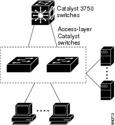
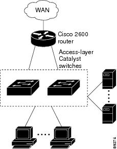
•![]() Cost-effective Gigabit-to-the-desktop for high-performance workgroups (Figure 1-1)—For high-speed access to network resources, you can use the Cisco Catalyst 2960 switches in the access layer to provide Gigabit Ethernet to the desktop. To prevent congestion, use QoS DSCP marking priorities on these switches. For high-speed IP forwarding at the distribution layer, connect the switches in the access layer to a Gigabit multilayer switch with routing capability, such as a Catalyst 3750 switch, or to a router.
Cost-effective Gigabit-to-the-desktop for high-performance workgroups (Figure 1-1)—For high-speed access to network resources, you can use the Cisco Catalyst 2960 switches in the access layer to provide Gigabit Ethernet to the desktop. To prevent congestion, use QoS DSCP marking priorities on these switches. For high-speed IP forwarding at the distribution layer, connect the switches in the access layer to a Gigabit multilayer switch with routing capability, such as a Catalyst 3750 switch, or to a router.
The first illustration is of an isolated high-performance workgroup, where the Catalyst 2960 switches are connected to Catalyst 3750 switches in the distribution layer. The second illustration is of a high-performance workgroup in a branch office, where the Catalyst 2960 switches are connected to a router in the distribution layer.
Each switch in this configuration provides users with a dedicated 1-Gb/s connection to network resources. Using SFP modules also provides flexibility in media and distance options through fiber-optic connections.
Figure 1-1 High-Performance Workgroup (Gigabit-to-the-Desktop)
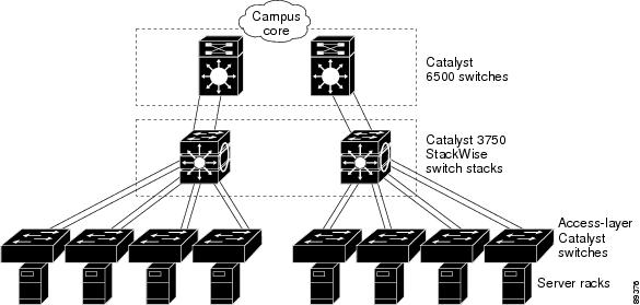
•![]() Server aggregation (Figure 1-2)—You can use the switches to interconnect groups of servers, centralizing physical security and administration of your network. For high-speed IP forwarding at the distribution layer, connect the switches in the access layer to multilayer switches with routing capability. The Gigabit interconnections minimize latency in the data flow.
Server aggregation (Figure 1-2)—You can use the switches to interconnect groups of servers, centralizing physical security and administration of your network. For high-speed IP forwarding at the distribution layer, connect the switches in the access layer to multilayer switches with routing capability. The Gigabit interconnections minimize latency in the data flow.
QoS and policing on the switches provide preferential treatment for certain data streams. They segment traffic streams into different paths for processing. Security features on the switch ensure rapid handling of packets.
Fault tolerance from the server racks to the core is achieved through dual homing of servers connected to switches, which have redundant Gigabit EtherChannels.
Using dual SFP module uplinks from the switches provides redundant uplinks to the network core. Using SFP modules provides flexibility in media and distance options through fiber-optic connections.
Figure 1-2 Server Aggregation
Small to Medium-Sized Network Using Catalyst 2960 Switches
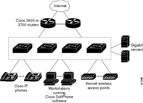
Figure 1-3 shows a configuration for a network of up to 500 employees. This network uses Catalyst 2960 switches with high-speed connections to two routers. This ensures connectivity to the Internet, WAN, and mission-critical network resources in case one of the routers fails. The switches are using EtherChannel for load sharing.
The switches are connected to workstations and local servers. The server farm includes a call-processing server running Cisco CallManager software. Cisco CallManager controls call processing, routing, and Cisco IP Phone features and configuration. The switches are interconnected through Gigabit interfaces.
This network uses VLANs to logically segment the network into well-defined broadcast groups and for security management. Data and multimedia traffic are configured on the same VLAN. Voice traffic from the Cisco IP Phones are configured on separate VVIDs. If data, multimedia, and voice traffic are assigned to the same VLAN, only one VLAN can be configured per wiring closet.
When an end station in one VLAN needs to communicate with an end station in another VLAN, a router routes the traffic to the destination VLAN. In this network, the routers are providing inter-VLAN routing. VLAN access control lists (VLAN maps) on the switch provide intra-VLAN security and prevent unauthorized users from accessing critical areas of the network.
In addition to inter-VLAN routing, the routers provide QoS mechanisms such as DSCP priorities to prioritize the different types of network traffic and to deliver high-priority traffic. If congestion occurs, QoS drops low-priority traffic to allow delivery of high-priority traffic.
Cisco CallManager controls call processing, routing, and Cisco IP Phone features and configuration. Users with workstations running Cisco SoftPhone software can place, receive, and control calls from their PCs. Using Cisco IP Phones, Cisco CallManager software, and Cisco SoftPhone software integrates telephony and IP networks, and the IP network supports both voice and data.
The routers also provide firewall services, Network Address Translation (NAT) services, voice-over-IP (VoIP) gateway services, and WAN and Internet access.
Figure 1-3 Catalyst 2960 Switches in a Collapsed Backbone Configuration
Where to Go Next
Before configuring the switch, review these sections for startup information:
•![]() "Using the Command-Line Interface"
"Using the Command-Line Interface"
•![]() "Assigning the Switch IP Address and Default Gateway"
"Assigning the Switch IP Address and Default Gateway"
 Feedback