Cisco Virtual Security Gateway for KVM Configuration Guide, Release 5.2(1)VSG2(1.3)
Bias-Free Language
The documentation set for this product strives to use bias-free language. For the purposes of this documentation set, bias-free is defined as language that does not imply discrimination based on age, disability, gender, racial identity, ethnic identity, sexual orientation, socioeconomic status, and intersectionality. Exceptions may be present in the documentation due to language that is hardcoded in the user interfaces of the product software, language used based on RFP documentation, or language that is used by a referenced third-party product. Learn more about how Cisco is using Inclusive Language.
- Updated:
- May 26, 2015
Chapter: Virtual Security Gateway Overview
- Information About the Cisco Virtual Security Gateway
- Cisco Virtual Security Gateway Configuration for the Network
- Setting Up Cisco VSGs in Layer 2 Mode
- Cisco VSG Configuration Overview
- Sequence in Configuring a Cisco VSG in the Layer 2 Mode
- Sequence in Configuring a Cisco VSG in the Layer 3 Mode
- Layer 2 Mode to Layer 3 Mode Migration
- Migrating from Layer 2 Mode to Layer 3 Mode
- Documentation Feedback
- Obtaining Documentation and Submitting a Service Request
Virtual Security Gateway Overview
This chapter contains the following sections:
- Information About the Cisco Virtual Security Gateway
- Cisco Virtual Security Gateway Configuration for the Network
Information About the Cisco Virtual Security Gateway
Document Conventions
Command descriptions use the following conventions:
| Convention | Description |
|---|---|
| bold |
Bold text indicates the commands and keywords that you enter literally as shown. |
| Italic |
Italic text indicates arguments for which the user supplies the values. |
| [x] |
Square brackets enclose an optional element (keyword or argument). |
| [x | y] |
Square brackets enclosing keywords or arguments separated by a vertical bar indicate an optional choice. |
| {x | y} |
Braces enclosing keywords or arguments separated by a vertical bar indicate a required choice. |
| [x {y | z}] |
Nested set of square brackets or braces indicate optional or required choices within optional or required elements. Braces and a vertical bar within square brackets indicate a required choice within an optional element. |
| variable |
Indicates a variable for which you supply values, in context where italics cannot be used. |
| string | A nonquoted set of characters. Do not use quotation marks around the string or the string will include the quotation marks. |
Examples use the following conventions:
| Convention | Description |
|---|---|
| screen font |
Terminal sessions and information the switch displays are in screen font. |
| boldface screen font |
Information you must enter is in boldface screen font. |
| italic screen font |
Arguments for which you supply values are in italic screen font. |
| < > |
Nonprinting characters, such as passwords, are in angle brackets. |
| [ ] |
Default responses to system prompts are in square brackets. |
| !, # |
An exclamation point (!) or a pound sign (#) at the beginning of a line of code indicates a comment line. |
This document uses the following conventions:
 Note | Means reader take note. Notes contain helpful suggestions or references to material not covered in the manual. |
 Caution | Means reader be careful. In this situation, you might do something that could result in equipment damage or loss of data. |
Overview
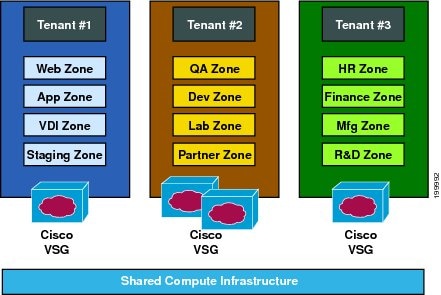
The Cisco Virtual Security Gateway (VSG) is a virtual firewall appliance that provides trusted access to virtual data center and cloud environments. The Cisco VSG enables a broad set of multi-tenant workloads that have varied security profiles to share a common compute infrastructure in a virtual data center private cloud or in a public cloud. By associating one or more virtual machines (VMs) into distinct trust zones, the Cisco VSG ensures that access to trust zones is controlled and monitored through established security policies.
-
Trusted multi-tenant access—Zone-based control and monitoring with context-aware security policies in a multi-tenant (scale-out) environment to strengthen regulatory compliance and simplify audits. Security policies are organized into security profile templates to simplify their management and deployment across many Cisco VSGs.
-
Dynamic operation—On-demand provisioning of security templates and trust zones during VM instantiation and mobility-transparent enforcement and monitoring as live migration of VMs occur across different physical servers.
-
Nondisruptive administration—Administrative segregation across security and server teams that provides collaboration, eliminates administrative errors, and simplifies audits.
-
Provides compliance with industry regulations.
-
Simplifies audit processes in virtualized environments.
-
Reduces costs by securely deploying virtualized workloads across multiple tenants on a shared compute infrastructure, whether in virtual data centers or private/public cloud computing environments.
VSG Models
The Cisco VSG is available in three different models (small, medium, and large) based on the memory, number of virtual CPUs, and CPU speed. Currently, only the small model type is supported on KVM. The following table lists the available Cisco VSG models:
|
VSG Models |
Memory |
CPU Speed |
Number of Virtual CPUs |
Network Adapters |
|---|---|---|---|---|
|
Small |
2 GB |
1.0 GHz |
1 |
3 |
|
Large |
2 GB |
1.5 GHz |
2 |
3 |
After you have installed a VSG instance, you should not change the VSG model. You can change the VSG model after installation using OpenStack dashboard. However, the VSG may not behave as expected after you change VSG model. The VSG CLI does not provide support to change the VSG model.
Product Architecture
The Cisco VSG operates with the Cisco Nexus 1000V in the KVM, and the Cisco VSG leverages the virtual network service datapath (Cisco vPath) that is embedded in the Cisco Nexus 1000V compute node.
-
Efficient deployment—Each Cisco VSG can protect access and traffic across multiple physical servers, which eliminates the need to deploy one virtual appliance per physical server.
-
Performance optimization—By off-loading fast-path to one or more Cisco Nexus 1000V compute node vPath modules, the Cisco VSG enhances network performance through distributed vPath-based enforcement.
-
Operational simplicity—The Cisco VSG can be transparently inserted in one-arm mode without creating multiple switches or temporarily migrating VMs to different switches or servers. Zone scaling is based on a security profile, not on vNICs that are limited for the virtual appliance. Zone scaling simplifies physical server upgrades without compromising security and incurring application outage.
-
High availability—For each tenant, the Cisco VSG can be deployed in an active-standby mode to ensure a highly available operating environment, with vPath redirecting packets to the standby Cisco VSG when the primary Cisco VSG is unavailable.
-
Independent capacity planning—The Cisco VSG can be placed on a dedicated server that is controlled by the security operations team so that maximum compute capacity can be allocated to application workloads. Capacity planning can occur independently across server and security teams, and operational segregation across security, network, and server teams can be maintained.

Fast Path Connection Timeouts
When a compute node sees a packet for a protected VM for the first time, the compute node redirects the packet to the Cisco VSG to determine what action needs to be taken (for example, permit, drop, or reset). After the decision is made, both the Cisco VSG and compute node save the connection information and the action for a period of time. During this time, packets for this connection follow the same action without any extra policy lookup. This connection is a connection in a fast path mode. Depending on the traffic and the action, the amount of time that a connection stays in the fast path mode varies. The following table provides the timeout details for the connections in the fast path mode.
|
Protocol |
Connection State |
Time Out |
|---|---|---|
|
TCP |
Close with FIN and ACKACK |
Compute Node—4 secs |
|
VSG—4 secs |
||
|
Close with RST |
Compute Node—4 secs |
|
|
VSG—4 secs |
||
|
Action drop |
Compute Node—4 secs |
|
|
VSG—4 secs |
||
|
Action reset |
Compute Node—4 secs |
|
|
VSG—4 secs |
||
|
Idle |
Compute Node—36–60 secs |
|
|
VSG—630–930 secs |
||
|
UDP |
Action drop |
Compute Node—4 secs |
|
VSG—4 secs |
||
|
Action reset |
Compute Node—4 secs |
|
|
VSG—4 secs |
||
|
Idle |
Compute Node—8–12 secs |
|
|
VSG—240–360 secs |
||
|
Destination Unreachable |
Compute Node—4 secs |
|
|
VSG—4 secs |
||
|
L3/ICMP |
Action drop |
Compute Node—2 secs |
|
VSG—2 secs |
||
|
Action reset |
Compute Node—2 secs |
|
|
VSG—2 secs |
||
|
Idle |
Compute Node—8–12 secs |
|
|
VSG—16–24 secs |
Trusted Multitenant Access
You can transparently insert a Cisco VSG into the KVM environment where the Cisco Nexus 1000V distributed virtual switch is deployed. One or more instances of the Cisco VSG is deployed on a per-tenant basis, which allows a high scale-out deployment across many tenants. Tenants are isolated from each other, so no traffic can cross tenant boundaries. You can deploy the Cisco VSG at the tenant level, at the virtual data center level, and at the vApp level.
As VMs are instantiated for a given tenant, their association to security profiles and zone membership occurs immediately through binding with the Cisco Nexus 1000V port profile. Each VM is placed upon instantiation into a logical trust zone. Security profiles contain context-aware rule sets that specify access policies for traffic that enters and exits each zone. In addition to VM and network contexts, security administrators can also use custom attributes to define zones directly through security profiles. Controls are applied to zone-to-zone traffic as well as to external-to-zone (and zone-to-external) traffic. Zone-based enforcement can also occur within a VLAN, as a VLAN often identifies a tenant boundary. The Cisco VSG evaluates access control rules and then, if configured, off-loads enforcement to the Cisco Nexus 1000V compute mode vPath module. The Cisco VSG can permit or deny access and optional access logs can be generated. The Cisco VSG also provides a policy-based traffic monitoring capability with access logs.
A Cisco VSG tenant can protect its VMs that span multiple hypervisors. Each tenant can also be assigned with an overlapping (private) IP address space, which is important in multi-tenant cloud environments.
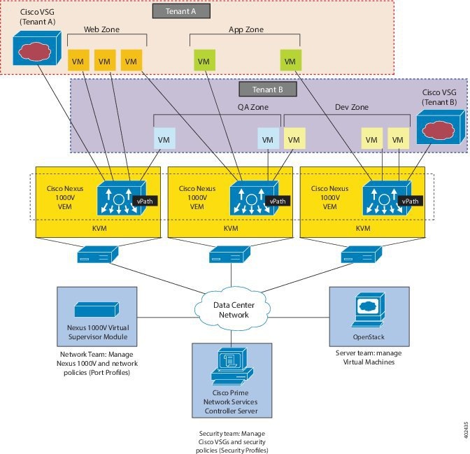
Dynamic (Virtualization-Aware) Operation
A virtualization environment is dynamic, where frequent additions, deletions, and changes occur across tenants and across VMs. Additionally, live migration of VMs can occur due to manual or programmatic VMotion events. The following figure shows how a structured environment can change over time due to this dynamic VM environment.
The Cisco VSG operating with the Cisco Nexus 1000V (and vPath) supports a dynamic VM environment. Typically, when you create a tenant on the Cisco Prime Network Services Controller (Prime NSC) with the Cisco VSG (standalone or active-standby pair), associated security profiles are defined that include trust zone definitions and access control rules. Each security profile is bound to a Cisco Nexus 1000V port profile (authored on the Cisco Nexus 1000V Virtual Supervisor Module [VSM] and published to the OpenStack dashboard). When a new VM is instantiated, the server administrator assigns port profiles to the virtual Ethernet port of the VM. Because the port profile uniquely refers to a security profile and VM zone membership, security controls are immediately applied. A VM can be repurposed by assigning a different port profile or security profile.
When VMotion events are triggered, VMs move across physical servers. Because the Cisco Nexus 1000V ensures that port profile policies follow the VMs, associated security profiles also follow these moving VMs, and security enforcement and monitoring remain transparent to VMotion events.
Cisco VSG Deployment Scenarios
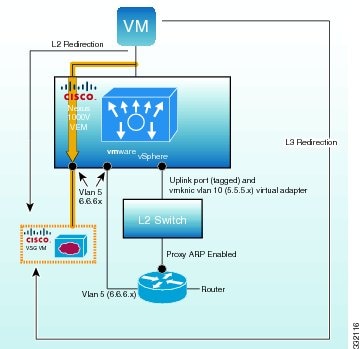
The current release supports the Cisco VSG deployment in the Layer 3 mode. The compute node and the Cisco VSG communicate with each other through a special virtual network interface called the Virtual Kernel NIC (vmknic). This vmknic is created by an administrator.
Compute Node Interface for a Cisco VSG in the Layer 3 Mode
When a compute node has a VM that is protected by the Cisco VSG in the Layer 3 mode, the compute node requires at least one IP/MAC pair to terminate the Cisco VSG packets in the Layer 3 mode. The compute node acts as an IP host (not a router) and supports only the IPv4 addresses.
The IP address to use for communication with the Cisco VSG in the Layer 3 mode is configured by assigning a port profile to a vmknic that has the capability l3-vservice command in it. For more details, see the Cisco Nexus 1000V System Management Configuration Guide.
To configure the vmknic interface that the compute node uses, you can assign a port profile by using the capability l3-vservice command in the port-profile configuration.
To carry the Cisco VSG in the Layer 3 mode traffic over multiple uplinks (or subgroups) in server configurations where vPC-HM MAC-pinning is required, you can configure up to four vmknic.
The traffic in the Layer 3 mode that is sourced by local vEthernet interfaces and needs to be redirected to the Cisco VSG is distributed between these vmknic based on the source MAC addresses in their frames. The compute node automatically pins the multiple vmknic in the Layer 3 mode to separate uplinks. If an uplink fails, the compute node automatically repins the vmknic to a working uplink.
When encapsulated traffic that is destined to a Cisco VSG is connected to a different subnet other than the vmknic subnet, the compute node does not use the KVM host routing table. Instead, the vmknic initiates an ARP for the remote Cisco VSG IP addresses. You must configure the upstream router to respond to a VSG IP address ARP request by using the Proxy ARP feature.
Cisco vPath
Cisco vPath is embedded in the Cisco Nexus 1000V Series switch compute node. It intercepts the VM to VM traffic and then redirects the traffic to the appropriate virtual service node. For details, see the Cisco vPath and vServices Reference Guide for KVM.
Cisco VSG Network Virtual Service
The Cisco network virtual service (vservice) is supported by the Cisco Nexus 1000V using the Cisco vPath. It provides trusted multi-tenant access and supports the VM mobility across physical servers for workload balancing, availability, or scalability. For details, see the Cisco vPath and vServices Reference Guide for KVM.
Cisco Virtual Security Gateway Configuration for the Network
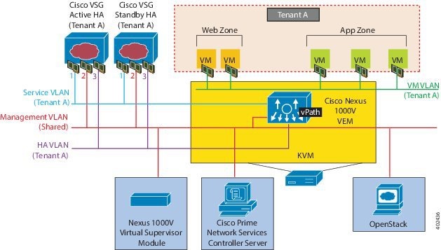
Setting Up Cisco VSGs in Layer 2 Mode
The Cisco VSG is set up so that VMs can reach a Cisco VSG irrespective of its location. The Cisco vPath component in the Cisco Nexus 1000V compute node intercepts the packets from the VM and sends them to the Cisco VSG for further processing.
-
The Management VLAN connects management platforms such as the Cisco Prime Network Services Controller (PNSC), the Cisco Nexus 1000V VSM, and the managed Cisco VSGs.
-
The Service VLAN provides communications between the Cisco Nexus 1000V compute node and Cisco VSGs. All the Cisco VSGs are part of the Service VLAN and the compute node uses this VLAN for its interaction with Cisco VSGs.
-
The HA VLAN is used for the HA heartbeat mechanism and identifies the master-slave relationship.
You can allocate one or more VM Data VLAN(s) for VM-to-VM communications. In a multi-tenant environment, the Management VLAN is shared among all the tenants, and the Service VLAN, HA VLAN, and VM Data VLAN are allocated per tenant. However, when VLAN resources become scarce, you might decide to use a single VLAN for Service and HA functions.
Cisco VSG Configuration Overview
When you install a Cisco VSG on a virtualized data center network, you must change the configuration of the Cisco Nexus 1000V Series switch VSM and the Cisco VSG.
Note | For information about how to configure the Cisco VSG for the Cisco Nexus 1000V Series switch and the Cisco Cloud Service Platform Virtual Services Appliance, see the Cisco vPath and vServices Reference Guide for KVM. |
- Cisco Nexus 1000V Series Switch VSM
- Port Profile
- Virtual Security Gateway
- Security Profile
- Firewall Policy
- Service Firewall Logging
Cisco Nexus 1000V Series Switch VSM
The VSM controls multiple compute nodes as one logical modular switch. Instead of physical line cards, the VSM supports compute nodes that run in software inside servers. Configurations are performed through the VSM and are automatically propagated to the compute nodes. Instead of configuring soft switches inside the hypervisor on one host at a time, you can define configurations for immediate use on all compute nodes that are managed by the VSM.
Port Profile
In the Cisco Nexus 1000V Series switch, you use port profiles to configure interfaces. Through a management interface on the VSM, you can assign a port profile to multiple interfaces, which provides all of them with the same configuration. Changes to the port profile can be propagated automatically to the configuration of any interface assigned to it.
Port profiles that are not configured as uplinks can be assigned to a VM virtual port. When binding with a security profile and a Cisco VSG IP address, a VM port profile can be used to provision security services (such as for VM segmentation) provided by a Cisco VSG.
Virtual Security Gateway
The Cisco VSG for the Cisco Nexus 1000V Series switch is a virtual firewall appliance that provides trusted access to the virtual data center and cloud environments. Administrators can install a Cisco VSG on a host as a service VM and configure it with security profiles and firewall policies to provide VM segmentation and other firewall functions to protect the access to VMs.
Security Profile
The Cisco Nexus 1000V Series switch port profile dynamically provisions network parameters for each VM. The same policy provisioning carries the network service configuration information so that each VM is dynamically provisioned with the network service policies when the VM is attached to the port profile. This process is similar to associating access control list (ACL) or quality of service (QoS) policies in the port profile. The information related to the network service configuration is created in an independent profile called the security profile and is attached to the port profile. The security administrator creates the security profile in the Cisco Prime NSC, and the network administrator associates it to an appropriate port profile in the VSM.
The security profile defines custom attributes that can be used to write policies. All the VMs tagged with a given port profile inherit the firewall policies and custom attributes defined in the security profile associated with that port profile. Each custom attribute is configured as a name value pair, such as state = CA. The network administrator also binds the associated Cisco VSG for a given port profile. The Cisco VSG associated with the port profile enforces firewall policies for the network traffic of the application VMs that are bound to that port profile. The same Cisco VSG is used irrespective of the location of the application VM. As a result, the policy is consistently enforced even during the VMotion procedures. You can also bind a specific policy to a service profile so that if any traffic is bound to a service profile, the policy associated with that service profile is executed. Both the service plane and the management plane support multi-tenancy requirements. Different tenants can have their own Cisco VSG (or set of Cisco VSGs), which enforce the policy defined by them. The Cisco vPath in each KVM host can intelligently redirect tenant traffic to the appropriate Cisco VSG.
Firewall Policy
You can use a firewall policy to enforce network traffic on a Cisco VSG. A key component of the Cisco VSG is the policy engine. The policy engine uses the policy as a configuration that filters the network traffic that is received on the Cisco VSG.
A policy is bound to a Cisco VSG by using a set of indirect associations. The security administrator can configure a security profile and then refer to a policy name within the security profile. The security profile is associated with a port profile that has a reference to a Cisco VSG.
Object Groups
An object group is a set of conditions relevant to an attribute. Because object groups and zones can be shared between various rules with different directions, the attributes used in an object group condition should not have a directional sense and must be neutral. An object group is a secondary policy object that assists in writing firewall rules. A rule condition can refer to an object group by using an operator.
Zones
A zone is a logical group of VMs or hosts. Zones simplify policy writing by allowing users to write policies based on zone attributes using zone names. The zone definitions map the VMs to the zones. The logical group definition can be based on the attributes associated with a VM , such as VM attributes. Zone definitions can be written as condition-based subnet and endpoint IP addresses.
Because zones and object groups can be shared between various rules with different directions, the attributes used in a zone should not have a directional sense and must be neutral.
Rules
Firewall rules can consist of multiple conditions and actions. Rules can be defined in a policy as a condition for filtering the traffic. The policy engine uses the policy as a configuration that filters the network traffic that is received on the . The policy engine uses two types of condition matching models for filtering the network traffic:
AND Model: A rule is set to matched when all the attributes in a rule match.
Actions
Service Firewall Logging
The service firewall log is a tool to test and debug the policy. During a policy evaluation, the policy engine displays the policy results of a policy evaluation. Both the users and the policy writer benefit from this tool when troubleshooting a policy.
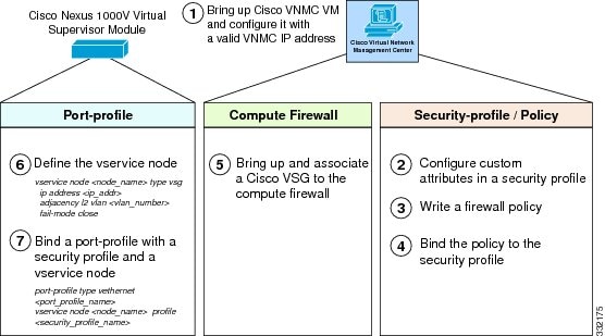
Sequence in Configuring a Cisco VSG in the Layer 2 Mode
-
Install and set up a Cisco Prime Network Services Controller (PNSC) service VM and configure the Cisco NSC with a valid IP address.
-
If you plan to use custom attributes in the firewall policy, create a set of custom attributes in a security profile configuration on the Cisco PNSC.
-
Write a firewall policy on the Cisco PNSC by using the appropriate policy objects such as object groups, zones, rules, conditions, actions, and policies.
-
After the firewall policy is created, bind the policy to the security profile that was previously created on the Cisco PNSC. This step is done with the security profile management interface.
-
Bring up a Cisco VSG and associate it to the appropriate compute firewall on the Cisco PNSC.
-
Define the vservice node.
-
After the security profile and firewall policy are fully configured, you can bind the security profile and the service nodes with the VM port profiles that demand access protection provided by the Cisco VSG through the port profile management interface on the VSM.
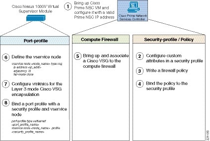
Sequence in Configuring a Cisco VSG in the Layer 3 Mode
Before configuring a Cisco VSG in Layer 3 mode, create a Layer 3 vmknic.
This section is an overview of the sequences that you, as an administrator, must follow when configuring a Cisco VSG in Layer 3 mode:
-
Install and set up a Cisco PNSC service VM and configure the Cisco PNSC with a valid IP address.
-
If you plan to use custom attributes in the firewall policy, create a set of custom attributes in a security profile configuration on the Cisco PNSC.
-
Write a firewall policy on the Cisco PNSC by using appropriate policy objects such as object groups, zones, rules, conditions, actions, and policies.
-
After the firewall policy is created, bind the policy to the security profile that was previously created on the Cisco PNSC.
-
Bring up a Cisco VSG and associate it to the appropriate compute firewall on the Cisco PNSC.
-
Configure the vmknic for the Layer 3 mode Cisco VSG encapsulation.
-
Configure VSG and virtual network adapter in same VLAN/network.
-
Define the vservice node.
-
After the security profile and firewall policy are fully configured, you can bind the security profile and the service node with the VM port profiles that demand access protection provided by the Cisco VSG through the port profile management interface on the VSM.
Layer 2 Mode to Layer 3 Mode Migration
This section provides an overview of the sequence to follow when migrating the Cisco VSG deployment from Layer 2 mode to Layer 3 mode.
Migrating from Layer 2 Mode to Layer 3 Mode
Documentation Feedback
To provide technical feedback on this document, or to report an error or omission, please send your comments to vsg-docfeedback@cisco.com. We appreciate your feedback.
Obtaining Documentation and Submitting a Service Request
For information on obtaining documentation, using the Cisco Bug Search Tool (BST), submitting a service request, and gathering additional information, see What's New in Cisco Product Documentation, at: http://www.cisco.com/c/en/us/td/docs/general/whatsnew/whatsnew.html.
Subscribe to What's New in Cisco Product Documentation, which lists all new and revised Cisco technical documentation as an RSS feed and delivers content directly to your desktop using a reader application. The RSS feeds are a free service.
 Feedback