- Index
- Preface
- Overview
- Part 1
- Quick Start Guide for Cisco Virtual Security Gateway and Cisco Virtual Network Management Center
- Part 2
- Installing the Cisco Virtual Security Gateway
- Part 3
- Installing the Cisco Virtual Network Management Center
- Registering Devices with the Cisco VNMC
- Part 4
- Installing the Cisco Virtual Security Gateway on a Cisco Nexus 1010 Appliance
- Part 5
- Upgrading the Cisco Virtual Security Gateway and Cisco Virtual Network Management Center
- Examples of Cisco VNMC OVA Template Deployment and Cisco VNMC ISO Installations
Cisco Virtual Security Gateway, Rel. 4.2(1)VSG1(2) and Cisco Virtual Network Management Center, Rel. 1.2 Installation and Upgrade
Bias-Free Language
The documentation set for this product strives to use bias-free language. For the purposes of this documentation set, bias-free is defined as language that does not imply discrimination based on age, disability, gender, racial identity, ethnic identity, sexual orientation, socioeconomic status, and intersectionality. Exceptions may be present in the documentation due to language that is hardcoded in the user interfaces of the product software, language used based on RFP documentation, or language that is used by a referenced third-party product. Learn more about how Cisco is using Inclusive Language.
- Updated:
- January 31, 2011
Chapter: Quick Start Guide for Cisco Virtual Security Gateway and Cisco Virtual Network Management Center
- Information About Installing Cisco VNMC and Cisco VSG
- Host Requirements
- Obtaining the Cisco VNMC and the Cisco VSG Software
- Task 1—Installing Cisco VNMC Software from an OVA Template
- Task 2—On the Cisco VNMC, Setting Up VM-Mgr for vCenter Connectivity
- Task 3—On the VSM, Configuring the Cisco VNMC Policy-Agent
- Task 4—On the VSM, Preparing Cisco VSG Port Profiles
- Task 5—Installing the Cisco VSG from an OVA Template
- Task 6—On the Cisco VSG and Cisco VNMC, Verifying the VNM Policy Agent Status
- Task 7—On the Cisco VNMC, Configuring a Tenant, Security Profile, and Compute Firewall
- Task 8—On the Cisco VNMC, Assigning the Cisco VSG to the Compute Firewall
- Task 9—On the Cisco VNMC, Configuring a Permit-All Rule
- Task 10—On the Cisco VSG, Verifying the Permit-All Rule
- Task 11—Enabling Logging
- Task 12—Enabling the Traffic VM's Port-Profile for Firewall Protection and Verifying the Communication Between the VSM, VEM, and VSG
- Task 13—Sending Traffic Flow and on the Cisco VSG Verifying Statistics and Logs
Quick Start Guide for the Cisco Virtual Security Gateway and the Cisco Virtual Network Management Center
This chapter provides a Quick Start reference for installing and completing the basic configuration for the Cisco Virtual Network Management Center (VNMC) and the Cisco Virtual Security Gateway (VSG) software.
This chapter includes the following sections:
•![]() Information About Installing Cisco VNMC and Cisco VSG
Information About Installing Cisco VNMC and Cisco VSG
•![]() Obtaining the Cisco VNMC and the Cisco VSG Software
Obtaining the Cisco VNMC and the Cisco VSG Software
•![]() Task 1—Installing Cisco VNMC Software from an OVA Template
Task 1—Installing Cisco VNMC Software from an OVA Template
•![]() Task 2—On the Cisco VNMC, Setting Up VM-Mgr for vCenter Connectivity
Task 2—On the Cisco VNMC, Setting Up VM-Mgr for vCenter Connectivity
•![]() Task 3—On the VSM, Configuring the Cisco VNMC Policy-Agent
Task 3—On the VSM, Configuring the Cisco VNMC Policy-Agent
•![]() Task 4—On the VSM, Preparing Cisco VSG Port Profiles
Task 4—On the VSM, Preparing Cisco VSG Port Profiles
•![]() Task 5—Installing the Cisco VSG from an OVA Template
Task 5—Installing the Cisco VSG from an OVA Template
•![]() Task 6—On the Cisco VSG and Cisco VNMC, Verifying the VNM Policy Agent Status
Task 6—On the Cisco VSG and Cisco VNMC, Verifying the VNM Policy Agent Status
•![]() Task 7—On the Cisco VNMC, Configuring a Tenant, Security Profile, and Compute Firewall
Task 7—On the Cisco VNMC, Configuring a Tenant, Security Profile, and Compute Firewall
•![]() Task 8—On the Cisco VNMC, Assigning the Cisco VSG to the Compute Firewall
Task 8—On the Cisco VNMC, Assigning the Cisco VSG to the Compute Firewall
•![]() Task 9—On the Cisco VNMC, Configuring a Permit-All Rule
Task 9—On the Cisco VNMC, Configuring a Permit-All Rule
•![]() Task 10—On the Cisco VSG, Verifying the Permit-All Rule
Task 10—On the Cisco VSG, Verifying the Permit-All Rule
•![]() Task 13—Sending Traffic Flow and on the Cisco VSG Verifying Statistics and Logs
Task 13—Sending Traffic Flow and on the Cisco VSG Verifying Statistics and Logs
Information About Installing Cisco VNMC and Cisco VSG
This chapter presents an example of an effective way to install and set up a basic working configuration of the Cisco VNMC and Cisco VSG. The example in this chapter uses the OVF template method to install the OVA files of the software. The steps assume that the Cisco Nexus 1000V is up and running and endpoint VMs are already installed.
Cisco VSG and Cisco VNMC Installation Planning Checklists
Planning the arrangement and architecture of your network and equipment is essential for successful operation of the Cisco VNMC and Cisco VSG. This section provides some planning and information checklists to assist you in installing the Cisco VNMC and Cisco VSG.
This section includes the following checklists:
•![]() Basic Hardware and Software Requirements
Basic Hardware and Software Requirements
•![]() Preparation of the Cisco Nexus 1000V Series Switch for Further Installation Processes
Preparation of the Cisco Nexus 1000V Series Switch for Further Installation Processes
•![]() Your Cisco VNMC and Cisco VSG Information for Use Later During Installation
Your Cisco VNMC and Cisco VSG Information for Use Later During Installation
•![]() Tasks, Descriptions, and Prerequisites Checklist
Tasks, Descriptions, and Prerequisites Checklist
Table 2-1 Basic Hardware and Software Requirements
|
|
|
|
|---|---|---|
|
|
x86 Intel or AMD server with 64-bit processor listed in the VMware compatibility matrix |
|
|
|
Intel VT enabled in the BIOS |
|
|
|
VMware ESX 4.0, 4.0 U1, 4.0 U2 or 4.1 |
|
|
|
ESX/ESXi platform that runs VMware software release 4.0.0 or 4.1.0 with a minimum of 4-GB physical RAM for the Cisco VSG and similar for the Cisco VNMC or 6-GB for both. |
|
|
|
VMware vSphere Hypervisor |
|
|
|
VMware vCenter 4.0, 4.0 U1, 4.0 U2 or 4.1 |
|
|
|
1 processor |
|
|
|
CPU speed of 1.5 Ghz |
|
|
|
Datastore with at least 25-GB disk space available on shared NFS/SAN storage when the Cisco VNMC is deployed in an HA cluster |
|
|
|
Internet Explorer 7.0 or Mozilla Firefox 3.6.x on Windows |
|
|
|
Flash 10.0 or 10.1 |
|
|
|
Cisco VSG software available for download at the following URL: http://www.cisco.com/en/US/products/ps13095/tsd_products_support_series_home.html |
|
|
|
Cisco VNMC software available for download at the following URL: |
Table 2-2 Preparation of the Cisco Nexus 1000V Series Switch for Further Installation Processes
Table 2-3 Your Cisco VNMC and Cisco VSG Information for Use Later During Installation
Table 2-4 Tasks, Descriptions, and Prerequisites Checklist
Host Requirements
The Cisco VSG and Cisco VNMC installations have the following host requirements:
•![]() ESX/ESXi platform that runs VMware software release 4.0.0 or 4.1.0 with a minimum of 4-GB physical RAM for the Cisco VSG and and similar requirements for the Cisco VNMC, or 6-GB for both.
ESX/ESXi platform that runs VMware software release 4.0.0 or 4.1.0 with a minimum of 4-GB physical RAM for the Cisco VSG and and similar requirements for the Cisco VNMC, or 6-GB for both.
•![]() 1 processor
1 processor
•![]() CPU speed of 1.5 GHz
CPU speed of 1.5 GHz
Obtaining the Cisco VNMC and the Cisco VSG Software
The Cisco VSG software is available for download at the following URL:
http://www.cisco.com/en/US/products/ps13095/tsd_products_support_series_home.html
The Cisco VNMC software is available for download at the following URL:
http://www.cisco.com/en/US/products/ps11213/index.html
Task 1—Installing Cisco VNMC Software from an OVA Template
As with most software application installations, there is an order of installation for the Cisco VNMC and the Cisco VSG that must be followed to ensure that all components work and communicate properly. This first task involves using an OVA Template to install the Cisco VNMC software.
BEFORE YOU BEGIN
Before starting the procedure, know or do the following:
•![]() Verify that the Cisco VNMC OVA image is available in the vCenter
Verify that the Cisco VNMC OVA image is available in the vCenter
•![]() IP/subnet mask/gateway information for the Cisco VNMC
IP/subnet mask/gateway information for the Cisco VNMC
•![]() The admin password, shared_secret, hostname that you want to use
The admin password, shared_secret, hostname that you want to use
•![]() The DNS server and domain name information
The DNS server and domain name information
•![]() The management port-profile name for the virtual machine (VM) (management)
The management port-profile name for the virtual machine (VM) (management)

Note ![]() The management port profile is the same port profile that is used for the VSM. The port profile is configured in the VSM and is used for the Cisco VNMC management interface.
The management port profile is the same port profile that is used for the VSM. The port profile is configured in the VSM and is used for the Cisco VNMC management interface.
•![]() Make sure that the host has 2-GB RAM and 25-GB available hard-disk space
Make sure that the host has 2-GB RAM and 25-GB available hard-disk space
•![]() Have a shared secret password available (this password is what enables communication between the Cisco VNMC, VSM, and Cisco VSG)
Have a shared secret password available (this password is what enables communication between the Cisco VNMC, VSM, and Cisco VSG)
PROCEDURE
Step 1 ![]() Choose the host on which to deploy the Cisco VNMC VM.
Choose the host on which to deploy the Cisco VNMC VM.
Step 2 ![]() From the File menu, choose Deploy OVF Template.
From the File menu, choose Deploy OVF Template.
The Deploy OVF Template window opens. See Figure 2-1.
Figure 2-1 Deploy OVF Template—Source Window
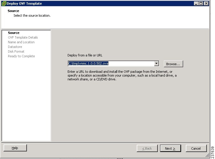
Step 3 ![]() In the Deploy from a file or URL field, enter the path to the Cisco VNMC OVA file and click Next.
In the Deploy from a file or URL field, enter the path to the Cisco VNMC OVA file and click Next.
The OVF Template Details window opens. See Figure 2-2.
Figure 2-2 Deploy OVF Template—OVF Template Details Window
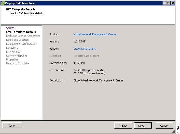
Step 4 ![]() Review the details of the Cisco VNMC template and click Next.
Review the details of the Cisco VNMC template and click Next.
The End User License Agreement window opens. See Figure 2-3.
Figure 2-3 Deploy OVF Template—End User License Agreement Window
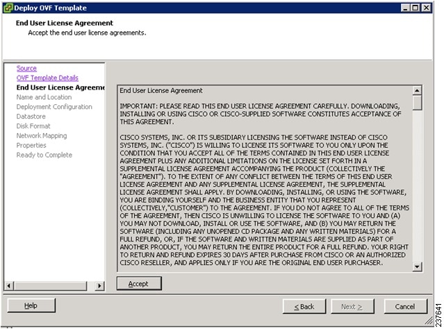
Step 5 ![]() Click Accept to accept the End User License Agreement and click Next.
Click Accept to accept the End User License Agreement and click Next.
The Name and Location window opens. See Figure 2-4.
Figure 2-4 Deploy OVF Template—Name and Location
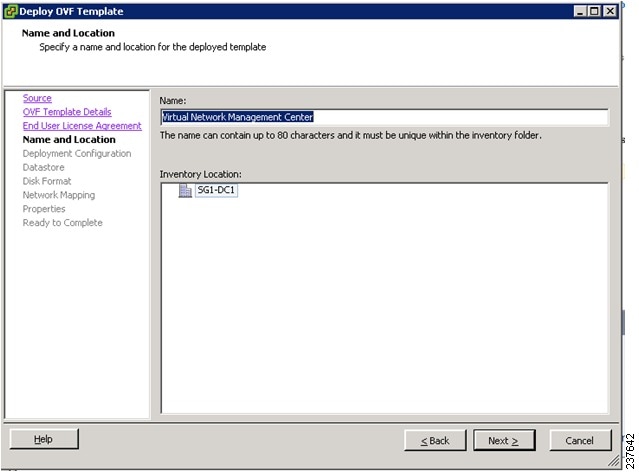
Step 6 ![]() In the Name field, enter the name of the Cisco Virtual Network Management Center. The name can contain up to 80 characters and i must be unique within the inventory folder.
In the Name field, enter the name of the Cisco Virtual Network Management Center. The name can contain up to 80 characters and i must be unique within the inventory folder.
Step 7 ![]() In the Inventory Location pane, choose the location that you would like to use and click Next.
In the Inventory Location pane, choose the location that you would like to use and click Next.
The Deployment Configuration window opens. See Figure 2-5.
Figure 2-5 Deploy OVF Template—Deployment Configuration Window
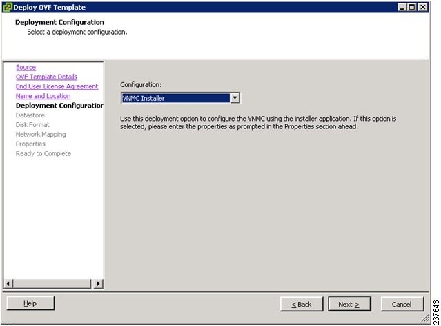
Step 8 ![]() From the Configuration drop-down list, choose VNMC Installer and click Next.
From the Configuration drop-down list, choose VNMC Installer and click Next.
The Datastore window opens. See Figure 2-6.
Figure 2-6 Deploy OVF Template—Datastore Window
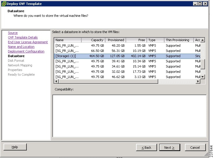
Step 9 ![]() In the Datastore pane, choose the datastore for the VM and click Next.
In the Datastore pane, choose the datastore for the VM and click Next.
Note ![]() The storage can be local or shared remote such as the network file storage (NFS) or the storage area network (SAN).
The storage can be local or shared remote such as the network file storage (NFS) or the storage area network (SAN).
Note ![]() If only one storage location is available for an ESX host, this window does not display and you are assigned to the one that is available.
If only one storage location is available for an ESX host, this window does not display and you are assigned to the one that is available.
The Disk Format window opens. See Figure 2-7.
Figure 2-7 Deploy OVF Template—Disk Format Window
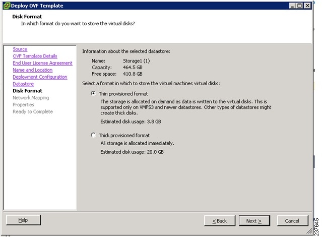
Step 10 ![]() Click either Thin provisioned format or Thick provisioned format to store the VM vdisks and click Next.
Click either Thin provisioned format or Thick provisioned format to store the VM vdisks and click Next.
Note ![]() The default is thick provisioned. If you do not want to allocate the storage immediately, use thin provisioned.
The default is thick provisioned. If you do not want to allocate the storage immediately, use thin provisioned.
Note ![]() Ignore the red text in the window.
Ignore the red text in the window.
The Network Mapping window opens. See Figure 2-8.
Figure 2-8 Deploy OVF Template—Network Mapping Window
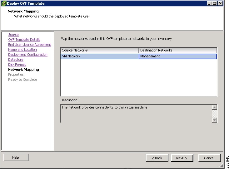
Step 11 ![]() In the network mapping pane, choose the management network port profile for the VM and click Next.
In the network mapping pane, choose the management network port profile for the VM and click Next.
The Properties window opens. See Figure 2-9.
Figure 2-9 Deploy OVF Template—Properties Window
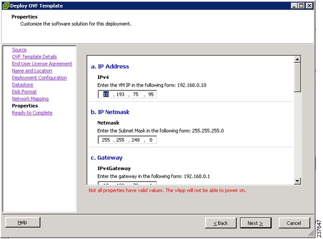
Step 12 ![]() Do the following:
Do the following:
a. ![]() In the IPv4 field, enter the IP address.
In the IPv4 field, enter the IP address.
b. ![]() In the Netmask field, enter the subnet mask.
In the Netmask field, enter the subnet mask.
c. ![]() In the IPv4Gateway field, enter the gateway.
In the IPv4Gateway field, enter the gateway.
d. ![]() In the Hostname section:
In the Hostname section:
–![]() In the DomainName field, enter the domain name.
In the DomainName field, enter the domain name.
–![]() In the DNS field, enter the domain name server name.
In the DNS field, enter the domain name server name.
e. ![]() In the Passwords section:
In the Passwords section:
–![]() In the Password field, enter the admin password.
In the Password field, enter the admin password.
–![]() In the Secret field, enter the shared secret password.
In the Secret field, enter the shared secret password.
Step 13 ![]() Click Next.
Click Next.
Note ![]() Make sure that red text messages do not appear before you click Next. If you do not want to enter valid information in the red-indicated fields, use null values to fill those fields. If those fields are left empty or filled with invalid null values, the application does not power on.
Make sure that red text messages do not appear before you click Next. If you do not want to enter valid information in the red-indicated fields, use null values to fill those fields. If those fields are left empty or filled with invalid null values, the application does not power on.
Note ![]() Ignore the VNMC Restore fields.
Ignore the VNMC Restore fields.
The Ready to Complete window opens. See Figure 2-10.
Figure 2-10 Deploy OVF Template—Ready to Complete Window
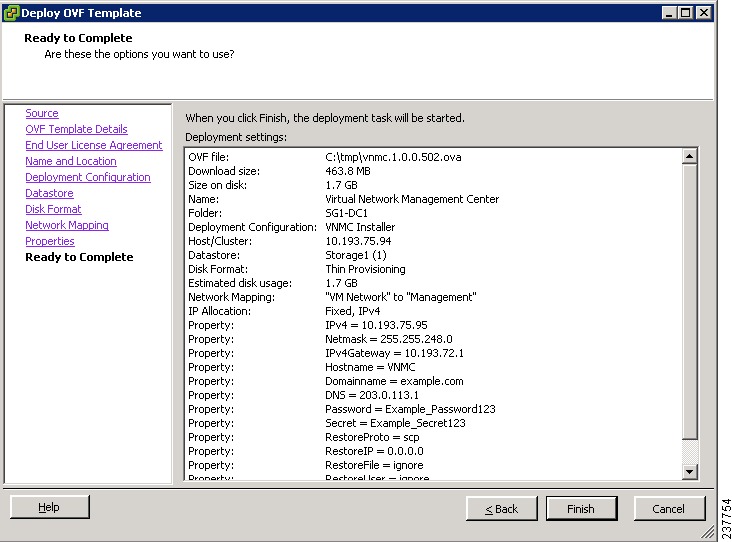
Step 14 ![]() Review the deployment settings information and click Finish.
Review the deployment settings information and click Finish.
Note ![]() Review the IP/mask/gateway information carefully because any discrepancies might cause the VM to have bootup issues.
Review the IP/mask/gateway information carefully because any discrepancies might cause the VM to have bootup issues.
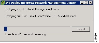
The Deploying Virtual Network Management Center progress indicator opens. See Figure 2-11.
The progress bar in Figure 2-11 shows how much of the deployment task is completed before the Cisco VNMC is deployed.
Figure 2-11 Deploying Virtual Network Management Center—Deploying Disk Files Progress Indicator
The progress indicator in Figure 2-12 shows that the deployment has completed successfully.
Figure 2-12
Deployment Completed Successfully Progress Indicator
Step 15 ![]() Click Close.
Click Close.
Step 16 ![]() Power on the Cisco VNMC VM.
Power on the Cisco VNMC VM.
Task 2—On the Cisco VNMC, Setting Up VM-Mgr for vCenter Connectivity
This section includes the following topics:
•![]() Downloading the vCenter Extension File from the Cisco VNMC
Downloading the vCenter Extension File from the Cisco VNMC
•![]() Registering the vCenter Extension Plugin in the vCenter
Registering the vCenter Extension Plugin in the vCenter
•![]() Configuring the vCenter in VM-Manager in the Cisco VNMC
Configuring the vCenter in VM-Manager in the Cisco VNMC
BEFORE YOU BEGIN
Before doing this procedure, know or do the following:
•![]() Install Adobe Flash Player (Version 10.1.102.64)
Install Adobe Flash Player (Version 10.1.102.64)
•![]() IP address of the Cisco VNMC
IP address of the Cisco VNMC
•![]() Admin user password
Admin user password
Downloading the vCenter Extension File from the Cisco VNMC
You can download the vCenter extension file from the Cisco VNMC.
PROCEDURE
Step 1 ![]() For Cisco VNMC access, from your client machine open Internet Explorer and access https://vnmc-ip/ (https://xxx.xxx.xxx.xxx).
For Cisco VNMC access, from your client machine open Internet Explorer and access https://vnmc-ip/ (https://xxx.xxx.xxx.xxx).
A Website Security Certification window opens. See Figure 2-13.
Figure 2-13 Website Security Certification Window
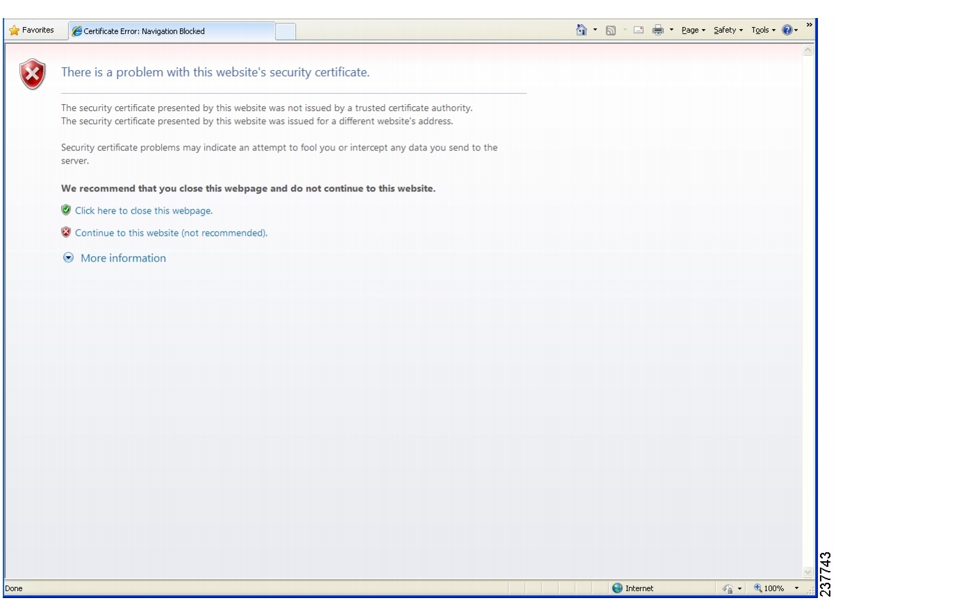
Step 2 ![]() On the certificate warning window, click Continue to this website.
On the certificate warning window, click Continue to this website.
The Cisco VNMC Access window opens. See Figure 2-14.
Figure 2-14 VNMC Access Window
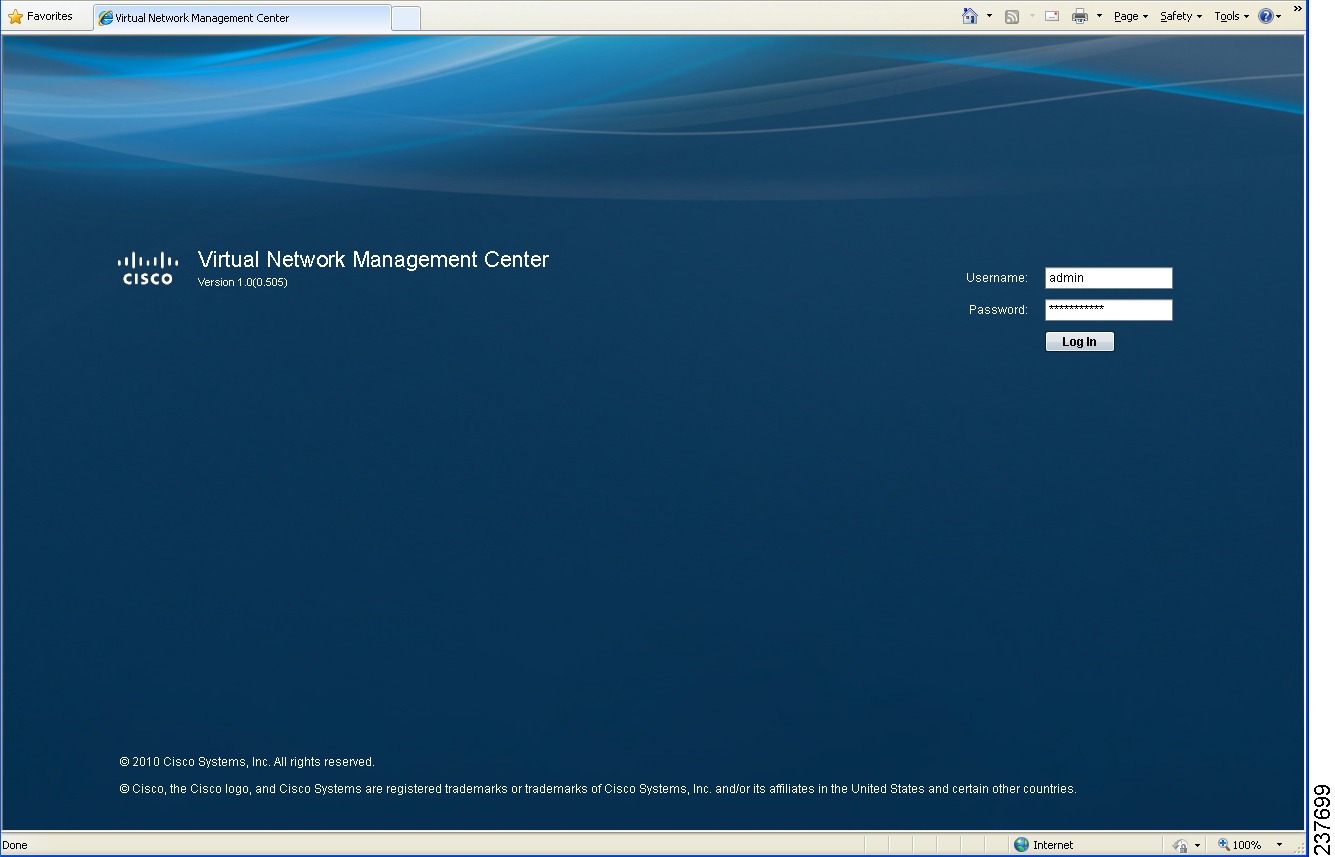
Step 3 ![]() Log in to the Cisco VNMC with the username "admin" and your password that you set when installing the application. The VNMC Main window opens. See Figure 2-15.
Log in to the Cisco VNMC with the username "admin" and your password that you set when installing the application. The VNMC Main window opens. See Figure 2-15.
Figure 2-15 Cisco Virtual Network Management Center—Opening Window
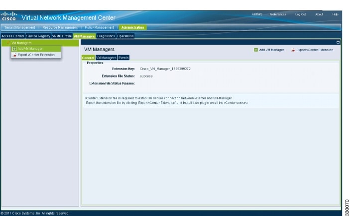
Step 4 ![]() Choose Administration > VM Managers. The Cisco Virtual Network Management Center VM Managers window opens. See Figure 2-16.
Choose Administration > VM Managers. The Cisco Virtual Network Management Center VM Managers window opens. See Figure 2-16.
Figure 2-16 Cisco VNMC Administration VM Managers Window
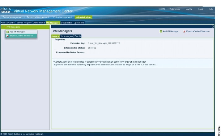
Step 5 ![]() From VM Managers, right-click and choose Export vCenter Extension, and save the file on your vCenter Desktop.
From VM Managers, right-click and choose Export vCenter Extension, and save the file on your vCenter Desktop.
Step 6 ![]() The vCenter Desktop displays as shown in Figure 2-17.
The vCenter Desktop displays as shown in Figure 2-17.
Registering the vCenter Extension Plugin in the vCenter
This task is completed from within your client desktop vSphere client directory.
PROCEDURE
Step 1 ![]() From vSphere client, log in to vCenter. See Figure 2-17.
From vSphere client, log in to vCenter. See Figure 2-17.
Figure 2-17 vSphere Client Directory Window
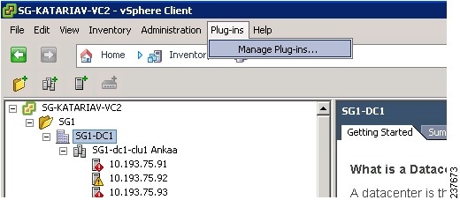
Step 2 ![]() Choose Plug-ins > Manage Plug-ins.
Choose Plug-ins > Manage Plug-ins.
Step 3 ![]() Right-click in an empty space, and in the drop-down list, choose New Plug-in.
Right-click in an empty space, and in the drop-down list, choose New Plug-in.
The Register Plug-in window that contains the vSphere client and vCenter directory for managing plug-ins opens. See Figure 2-18.
Figure 2-18 vSphere Client and vCenter Directory for Managing Plug-ins with Security Warning
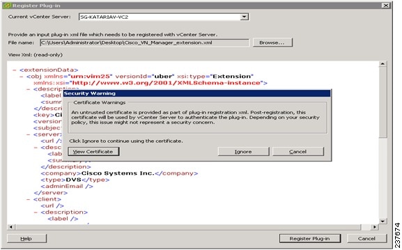
Step 4 ![]() Browse to the Cisco VNMC vCenter extension file and click Register Plug-in.
Browse to the Cisco VNMC vCenter extension file and click Register Plug-in.
Step 5 ![]() On the security warning that displays, click Ignore.
On the security warning that displays, click Ignore.
The Register Plug-in progress indicator opens. When the registration has completed successfully, the successful registration message will display. See Figure 2-19.
Figure 2-19 Register Plug-in Progress Success Indicator
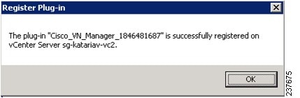
Step 6 ![]() Click OK.
Click OK.
Step 7 ![]() Click Close.
Click Close.
Configuring the vCenter in VM-Manager in the Cisco VNMC
You can configure the vCenter in VM-Manager in the Cisco VNMC.
PROCEDURE
Step 1 ![]() Return to the Cisco VNMC and click Administration > VM Managers.
Return to the Cisco VNMC and click Administration > VM Managers.
The Cisco VNMC Administration VM Managers window opens. See Figure 2-20.
Figure 2-20 Cisco VNMC Administration VM Managers Window
Step 2 ![]() Choose VM Managers > Add VM Manager.
Choose VM Managers > Add VM Manager.
The Add VM Manager dialog box opens. See Figure 2-21.
Figure 2-21 Add VM Manager Dialog Box
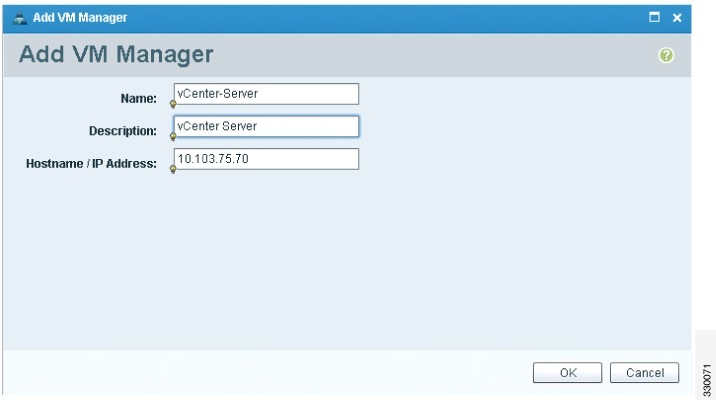
Step 3 ![]() In the Add VM Manager dialog box, do the following:
In the Add VM Manager dialog box, do the following:
a. ![]() In the Name field, enter the vCenter name (no spaces allowed).
In the Name field, enter the vCenter name (no spaces allowed).
b. ![]() In the Description field, enter a brief description of the vCenter.
In the Description field, enter a brief description of the vCenter.
c. ![]() In the Hostname/IP Address field, enter the vCenter IP address.
In the Hostname/IP Address field, enter the vCenter IP address.
Step 4 ![]() Click OK.
Click OK.
Note ![]() The successful addition should display the Admin State as enable and the Operational State as up with the version information.
The successful addition should display the Admin State as enable and the Operational State as up with the version information.
Task 3—On the VSM, Configuring the Cisco VNMC Policy-Agent
Once you have the Cisco VNMC installed, you must register the Virtual Supervisor Module (VSM) with the Cisco VNMC policy agent.
BEFORE YOU BEGIN
Before starting the procedure, know or do the following:
•![]() Make sure that the Cisco VNMC policy-agent image is available on the VSM (for example, vnmc-vsmpa.1.0.1j.bin)
Make sure that the Cisco VNMC policy-agent image is available on the VSM (for example, vnmc-vsmpa.1.0.1j.bin)
Note ![]() The string vsmpa must appear in the image name as highlighted.
The string vsmpa must appear in the image name as highlighted.
•![]() The IP address of the Cisco VNMC
The IP address of the Cisco VNMC
•![]() The shared secret password you defined during Cisco VNMC installation
The shared secret password you defined during Cisco VNMC installation
•![]() Make sure that IP connectivity between the VSM and the Cisco VNMC is okay.
Make sure that IP connectivity between the VSM and the Cisco VNMC is okay.
Note ![]() If you have upgraded your VSM to 1.4, you need to copy the VSM policy agent image, available in VNMC image bundle, to bootflash to complete registration with VNMC.
If you have upgraded your VSM to 1.4, you need to copy the VSM policy agent image, available in VNMC image bundle, to bootflash to complete registration with VNMC.
PROCEDURE
Step 1 ![]() On the VSM, enter the following commands:
On the VSM, enter the following commands:
vsm# configure terminal
vsm(config)# vnm-policy-agent
vsm(config-vnm-policy-agent)# registration-ip 10.193.75.95
vsm(config-vnm-policy-agent)# shared-secret Example_Secret123
vsm(config-vnm-policy-agent)# policy-agent-image vnmc-vsmpa.1.0.1j.bin
vsm(config-vnm-policy-agent)# exit
vsm(config)# copy running-config startup-config
vsm(config)# exit
Step 2 ![]() Check the status of the VNM policy agent configuration to verify that you have installed the Cisco VNMC correctly and it is reachable by entering the show vnm-pa status command.
Check the status of the VNM policy agent configuration to verify that you have installed the Cisco VNMC correctly and it is reachable by entering the show vnm-pa status command.
This example shows that the Cisco VNMC is reachable and the installation is correct:
vsm# show vnm-pa status
VNM Policy-Agent status is - Installed Successfully. Version 1.0(1j)-vsm
vsm#
The VSM is now registered with the Cisco VNMC.
EXAMPLES
This example shows that the Cisco VNMC is unreachable or an incorrect IP is configured:
vsm# show vnm-pa status
VNM Policy-Agent status is - Installation Failure
VNMC not reachable.
vsm#
This example shows that the VNM policy-agent is not configured or installed:
vsm# show vnm-pa status
VNM Policy-Agent status is - Not Installed
Task 4—On the VSM, Preparing Cisco VSG Port Profiles
To prepare Cisco VSG port profiles, you must create the VLANs and use the VLANs in the Cisco VSG data port profile and the Cisco VSG HA port profile.
BEFORE YOU BEGIN
Before starting the procedure, know or do the following:
•![]() The uplink port-profile name
The uplink port-profile name
•![]() The VLAN ID for the Cisco VSG data interface (for example,100)
The VLAN ID for the Cisco VSG data interface (for example,100)
•![]() The VLAN ID for the Cisco VSG HA interface (for example, 200)
The VLAN ID for the Cisco VSG HA interface (for example, 200)
•![]() The management VLAN (management)
The management VLAN (management)
Note ![]() None of these VLANs need to be system VLANs.
None of these VLANs need to be system VLANs.
PROCEDURE
Step 1 ![]() On the VSM, create the VLANs by first entering global configuration mode using the following command:
On the VSM, create the VLANs by first entering global configuration mode using the following command:
vsm# configure
Step 2 ![]() Enter the following configuration commands.
Enter the following configuration commands.
vsm(config)# vlan 100
vsm(config-vlan)# no shutdown
vsm(config-vlan)# exit
vsm(config)# vlan 200
vsm(config-vlan)# no shutdown
vsm(config-vlan)# exit
vsm(config)# exit
vsm# configure
vsm(config)# copy running-config startup-config
vsm(config)# exit
Step 3 ![]() To exit, press Ctrl-Z.
To exit, press Ctrl-Z.
Step 4 ![]() Create a Cisco VSG data port profile and a Cisco VSG HA port profile by first enabling the Cisco VSG data port-profile configuration mode. Use the configure command to enter global configuration mode.
Create a Cisco VSG data port profile and a Cisco VSG HA port profile by first enabling the Cisco VSG data port-profile configuration mode. Use the configure command to enter global configuration mode.
vsm# configure
Step 5 ![]() Enter the following configuration commands.
Enter the following configuration commands.
vsm(config)# port-profile VSG-Data
vsm(config-port-prof)# vmware port-group
vsm(config-port-prof)# switchport mode access
vsm(config-port-prof)# switchport access vlan 100
vsm(config-port-prof)# no shutdown
vsm(config-port-prof)# state enabled
vsm(config-port-prof)# exit
vsm(config)#
vsm(config)# copy running-config startup-config
vsm(config)# exit
Step 6 ![]() To end the session, press Ctrl-Z.
To end the session, press Ctrl-Z.
Step 7 ![]() Enable the Cisco VSG HA port profile configuration mode.
Enable the Cisco VSG HA port profile configuration mode.
vsm# configure
Step 8 ![]() Enter the following configuration commands.
Enter the following configuration commands.
vsm(config)# port-profile VSG-HA
vsm(config-port-prof)# vmware port-group
vsm(config-port-prof)# switchport mode access
vsm(config-port-prof)# switchport access vlan 200
vsm(config-port-prof)# no shutdown
vsm(config-port-prof)# state enabled
vsm(config-port-prof)# exit
vsm(config)#
vsm(config)# copy running-config startup-config
vsm(config)# exit
Step 9 ![]() Add the VLANs created for the Cisco VSG data and Cisco VSG HA interfaces as part of the allowed VLANs into the uplink port-profile. Use the configure command to enter global configuration mode.
Add the VLANs created for the Cisco VSG data and Cisco VSG HA interfaces as part of the allowed VLANs into the uplink port-profile. Use the configure command to enter global configuration mode.
vsm# configure
Step 10 ![]() Enter the following configuration commands:
Enter the following configuration commands:
vsm(config)# port-profile type ethernet uplink
vsm(config-port-prof)# switchport trunk allowed vlan add 100, 200
vsm(config-port-prof)# exit
vsm(config)#
To end the session, press Ctrl-Z.
Task 5—Installing the Cisco VSG from an OVA Template
Once you have installed the Cisco Virtual Network Management Center (Cisco VNMC), configured the Cisco VNM policy agent on the VSM, and prepared the Cisco VSG port profiles by creating the VLANs that will be used, you now must install the Cisco VSG.
For this example, the OVF Template is used to install a Cisco VSG in standalone mode.
BEFORE YOU BEGIN
Before starting the procedure, know or do the following:
•![]() Make sure that the Cisco VSG OVA image is available in the vCenter
Make sure that the Cisco VSG OVA image is available in the vCenter
•![]() Cisco VSG-data and Cisco VSG-HA port profile created on VSM
Cisco VSG-data and Cisco VSG-HA port profile created on VSM
•![]() Management port-profile (management)
Management port-profile (management)
Note ![]() The management port profile is the same port profile that is used for the VSM. The port profile is configured in the VSM and is used for the Cisco VNMC management interface.
The management port profile is the same port profile that is used for the VSM. The port profile is configured in the VSM and is used for the Cisco VNMC management interface.
•![]() HA ID
HA ID
•![]() IP/subnet mask/gateway information for the Cisco VSG
IP/subnet mask/gateway information for the Cisco VSG
•![]() Admin password
Admin password
•![]() 2-GB RAM and 3-GB hard disk space
2-GB RAM and 3-GB hard disk space
•![]() Cisco VNMC IP
Cisco VNMC IP
•![]() Shared secret
Shared secret
•![]() IP connectivity between Cisco VSG and Cisco VNMC is okay
IP connectivity between Cisco VSG and Cisco VNMC is okay
•![]() Cisco VSG VNM-PA image name (vnmc-vsgpa.1.0.1j.bin)
Cisco VSG VNM-PA image name (vnmc-vsgpa.1.0.1j.bin)
PROCEDURE
Step 1 ![]() Choose your host on which to deploy the Cisco VSG VM.
Choose your host on which to deploy the Cisco VSG VM.
Step 2 ![]() From the File menu, choose Deploy OVF Template.
From the File menu, choose Deploy OVF Template.
The Source window opens. See Figure 2-22.
Figure 2-22 Deploy OVF Template—Source Window
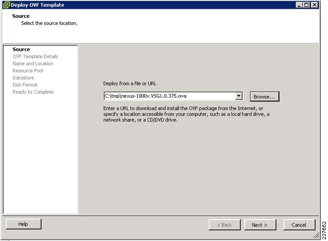
Step 3 ![]() In the Deploy from a file or URL field, enter the path to the Cisco VSG OVA file and click Next.
In the Deploy from a file or URL field, enter the path to the Cisco VSG OVA file and click Next.
The OVF Template Details window opens. See Figure 2-23.
Figure 2-23 Deploy OVF Template—OVF Template Details Window
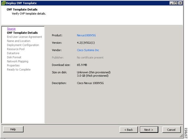
Step 4 ![]() Review the details of the Cisco VSG template and click Next.
Review the details of the Cisco VSG template and click Next.
The End User License Agreement window opens. See Figure 2-24.
Figure 2-24 Deploy OVF Template—End User License Agreement Window

Step 5 ![]() Click Accept to accept the End User License Agreement.
Click Accept to accept the End User License Agreement.
Step 6 ![]() Click Next.
Click Next.
The Name and Location window opens. See Figure 2-25.
Figure 2-25 Deploy OVF Template—Name and Location Window
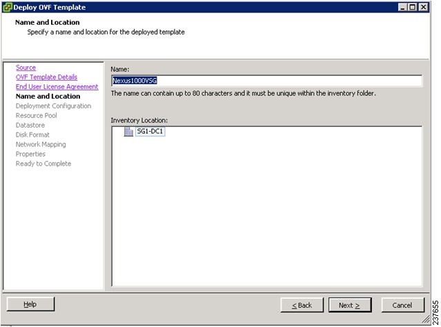
Step 7 ![]() In the Name field, enter the name that you want to use for the Cisco VSG.
In the Name field, enter the name that you want to use for the Cisco VSG.
Step 8 ![]() In the Inventory Location field, choose the location that you want to use for hosting the Cisco VSG.
In the Inventory Location field, choose the location that you want to use for hosting the Cisco VSG.
Step 9 ![]() Click Next.
Click Next.
The Deployment Configuration window opens. See Figure 2-26.
Figure 2-26 Deploy OVF Template—Deployment Configuration Window
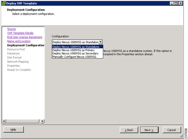
Step 10 ![]() From the Configuration drop-down list, choose Deploy Nexus 1000V as Standalone and click Next.
From the Configuration drop-down list, choose Deploy Nexus 1000V as Standalone and click Next.
The Datastore window opens. See Figure 2-27.
Figure 2-27 Deploy OVF Template—Datastore Window

Step 11 ![]() In the Select a datastore in which to store the VM files pane, choose the datastore for the VM and click Next.
In the Select a datastore in which to store the VM files pane, choose the datastore for the VM and click Next.
Note ![]() Storage can be local or shared-remote such as a network file storage (NFS) or a storage area network (SAN).
Storage can be local or shared-remote such as a network file storage (NFS) or a storage area network (SAN).
Note ![]() If only one storage location is available for an ESX host, this window does not display and you are assigned to the storage location that is available.
If only one storage location is available for an ESX host, this window does not display and you are assigned to the storage location that is available.
The Disk Format window opens. See Figure 2-28.
Figure 2-28 Deploy OVF Template—Disk Format Window
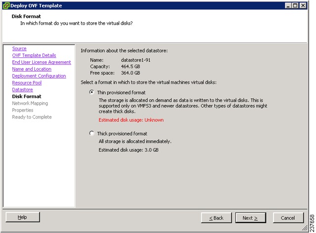
Step 12 ![]() Click either Thin provisioned format or Thick provisioned format to store the VM vdisks and click Next.
Click either Thin provisioned format or Thick provisioned format to store the VM vdisks and click Next.
Note ![]() The default is thick provisioned. If you do not want to allocate the storage immediately, use thin provisioned.
The default is thick provisioned. If you do not want to allocate the storage immediately, use thin provisioned.
Note ![]() Ignore the red text in the window.
Ignore the red text in the window.
The Network Mapping window opens. See Figure 2-29.
Figure 2-29 Deploy OVF Template—Network Mapping Window
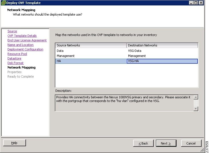
Step 13 ![]() Choose the data interface port profile as VSG-Data, choose the management interface port profile as Management, and choose the HA interface port profile as VSG-HA.
Choose the data interface port profile as VSG-Data, choose the management interface port profile as Management, and choose the HA interface port profile as VSG-HA.
Step 14 ![]() Click Next.
Click Next.
Note ![]() In this example, for VSG-Data and VSG-HA port profiles created in Task 4—On the VSM, Preparing Cisco VSG Port Profiles, the management port profile is used for management connectivity and is the same as in the VSM and Cisco VNMC.
In this example, for VSG-Data and VSG-HA port profiles created in Task 4—On the VSM, Preparing Cisco VSG Port Profiles, the management port profile is used for management connectivity and is the same as in the VSM and Cisco VNMC.
The Properties window opens. See Figure 2-30.
Figure 2-30 Deploy OVF Template—Properties Window
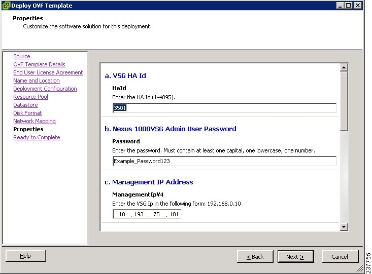
Step 15 ![]() Do the following:
Do the following:
a. ![]() In the HaId field, enter the high-availability identification number for a Cisco VSG pair (value from 1 through 4095).
In the HaId field, enter the high-availability identification number for a Cisco VSG pair (value from 1 through 4095).
b. ![]() In the Password field, enter a password that contains at least one uppercase letter, one lowercase letter, and one number.
In the Password field, enter a password that contains at least one uppercase letter, one lowercase letter, and one number.
c. ![]() In the Management IP Address section, do the following:
In the Management IP Address section, do the following:
–![]() In the ManagementIpV4 field, enter the IP address for the Cisco VSG.
In the ManagementIpV4 field, enter the IP address for the Cisco VSG.
–![]() In the ManagementIpV4 Subnet field, enter the subnet mask.
In the ManagementIpV4 Subnet field, enter the subnet mask.
d. ![]() In the Gateway field, enter the gateway name.
In the Gateway field, enter the gateway name.
e. ![]() In the VnmcIpV4 field, enter the IP address of the Cisco VNMC.
In the VnmcIpV4 field, enter the IP address of the Cisco VNMC.
f. ![]() In the SharedSecret field, enter the shared secret password defined during the Cisco VNMC installation.
In the SharedSecret field, enter the shared secret password defined during the Cisco VNMC installation.
g. ![]() In the ImageName field, enter the VSG VNM-PA image name (vnmc-vsgpa.1.0.1j.bin)
In the ImageName field, enter the VSG VNM-PA image name (vnmc-vsgpa.1.0.1j.bin)
Step 16 ![]() Click Next.
Click Next.
Note ![]() Make sure that red text messages do not appear before you click Next. If you do not want to enter valid information in the red-indicated fields, use null values to fill those fields. If those fields are left empty or filled with invalid null values, the application does not power on.
Make sure that red text messages do not appear before you click Next. If you do not want to enter valid information in the red-indicated fields, use null values to fill those fields. If those fields are left empty or filled with invalid null values, the application does not power on.
The Ready to Complete window opens. See Figure 2-31.
Figure 2-31 Deploy OVF Template—Ready to Complete Window
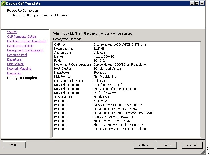
Step 17 ![]() Review the deployment settings information and click Finish.
Review the deployment settings information and click Finish.
Note ![]() Review the IP/mask/gateway information carefully because any discrepancies might cause the VM to have bootup issues.
Review the IP/mask/gateway information carefully because any discrepancies might cause the VM to have bootup issues.
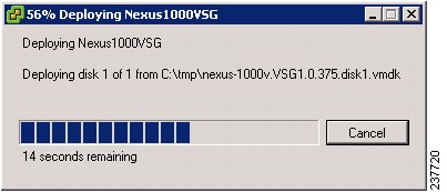
The Deploying Nexus1000VSG Progress Indicator opens. See Figure 2-32.
The progress bar in Figure 2-32 shows how much of the deployment task is completed before the Cisco VSG is deployed.
Figure 2-32 Deploying Nexus1000VSG—Deploying Disk Files Progress Indicator
The progress indicator in Figure 2-33 shows that the deployment has completed successfully.
Figure 2-33
Deployment Completed Successfully Progress Indicator
Step 18 ![]() Click Close.
Click Close.
Step 19 ![]() Power On the Cisco VSG VM
Power On the Cisco VSG VM
Task 6—On the Cisco VSG and Cisco VNMC, Verifying the VNM Policy Agent Status
You can use the show vnm-pa status command to verify the VNM policy agent status (which can indicate that you have installed the VNM successfully).
PROCEDURE
Step 1 ![]() Log in to the Cisco VSG.
Log in to the Cisco VSG.
Step 2 ![]() Check the status of VNM-PA configuration by entering the following command:
Check the status of VNM-PA configuration by entering the following command:
vsg# show vnm-pa status
VNM Policy-Agent status is - Installed Successfully. Version 1.0(1j)-vsg
vsg#
Step 3 ![]() Log in to the Cisco VNMC.
Log in to the Cisco VNMC.
Step 4 ![]() Choose Administration > Service Registry > Clients > General. The VNMC Administration Service Registry Window opens. See Figure 2-34.
Choose Administration > Service Registry > Clients > General. The VNMC Administration Service Registry Window opens. See Figure 2-34.
Figure 2-34 VNMC Administration Service Registry Window
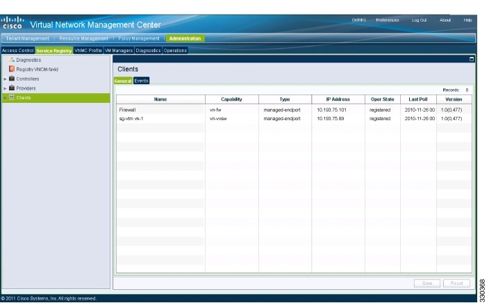
Step 5 ![]() In the Clients pane, verify that the Cisco VSG and VSM information is listed.
In the Clients pane, verify that the Cisco VSG and VSM information is listed.
Task 7—On the Cisco VNMC, Configuring a Tenant, Security Profile, and Compute Firewall
Now that you have the Cisco VNMC and the Cisco VSG successfully installed with the basic configurations (completed through the OVA File Template wizard), you should configure some of the basic security profiles and policies.
BEFORE YOU BEGIN
Before doing this procedure, know or do the following:
•![]() Install Adobe Flash Player (Version 10.1.102.64 or later)
Install Adobe Flash Player (Version 10.1.102.64 or later)
•![]() IP address of the Cisco VNMC
IP address of the Cisco VNMC
•![]() Admin user password
Admin user password
PROCEDURE
Step 1 ![]() For Cisco VNMC access, from your client machine, open Internet Explorer and access https://vnmc-ip/ (https://xxx.xxx.xxx.xxx).
For Cisco VNMC access, from your client machine, open Internet Explorer and access https://vnmc-ip/ (https://xxx.xxx.xxx.xxx).
A Website Security Certification window opens. See Figure 2-35.
Figure 2-35 Website Security Certification Window

Step 2 ![]() On the certificate warning, click Continue to this website.
On the certificate warning, click Continue to this website.
The Cisco VNMC Access window opens. See Figure 2-36.
Figure 2-36 VNMC Access Window
Step 3 ![]() Log in to the Cisco VNMC with the username "admin" and your password.
Log in to the Cisco VNMC with the username "admin" and your password.
Step 4 ![]() The Cisco VNMC Main window opens. See Figure 2-37.
The Cisco VNMC Main window opens. See Figure 2-37.
Figure 2-37 Cisco Virtual Network Management Center—Opening Page
Step 5 ![]() Choose Administration > Service Registry > Clients to check the Cisco VSG and VSM registration in the Cisco VNMC.
Choose Administration > Service Registry > Clients to check the Cisco VSG and VSM registration in the Cisco VNMC.
The Clients pane of the Cisco VNMC opens. See Figure 2-38.
Figure 2-38 VNMC Administration Service Registry Window Clients Pane
The Cisco VSG and VSM information should be listed in the Clients pane.
Configuring a Tenant in the Cisco VNMC
Tenants are entities (businesses, agencies, institutions, and so on) whose data and processes are hosted on virtual machines (VMs) on the virtual data center. To provide firewall security for each tenant, the tenant must first be configured in the Cisco VNMC.
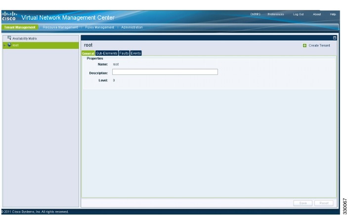
Step 1 ![]() From the Cisco VNMC top toolbar, click the Tenant Management tab.
From the Cisco VNMC top toolbar, click the Tenant Management tab.
The root pane opens. See Figure 2-39.
Figure 2-39 VNMC Window Tenant Management Tab root Pane
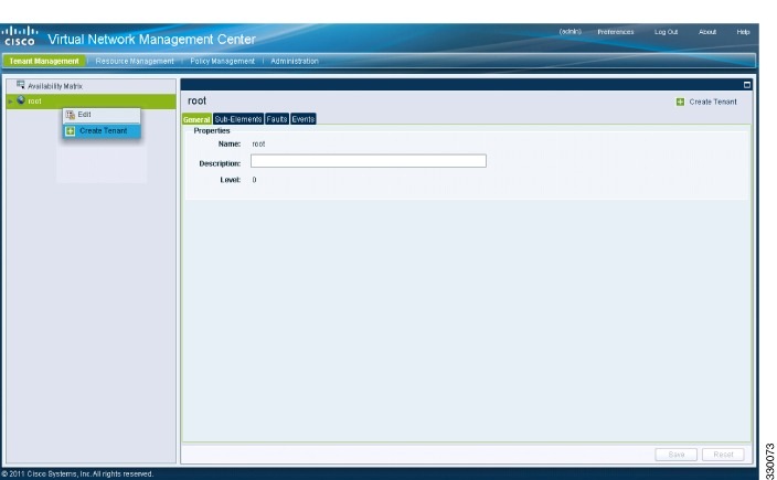
Step 2 ![]() In the left pane directory tree right-click on Root, and from the drop-down list, choose Create Tenant.
In the left pane directory tree right-click on Root, and from the drop-down list, choose Create Tenant.
The Create Tenant dialog box opens. See Figure 2-40.
Figure 2-40 Create Tenant Dialog Box
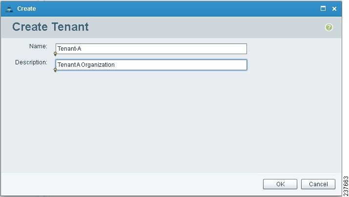
Step 3 ![]() Do the following:
Do the following:
a. ![]() In the Name field, enter the tenant name; for example, Tenant-A.
In the Name field, enter the tenant name; for example, Tenant-A.
b. ![]() In the Description field, enter a description for that tenant.
In the Description field, enter a description for that tenant.
Step 4 ![]() Click OK.
Click OK.
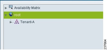
Notice that the tenant you just created is now listed in the left-side pane under root. See Figure 2-41.
Figure 2-41 Cisco VNMC VSG Configuration Directory Tree Pane
Configuring a Security Profile in the Cisco VNMC
You can configure a security profile on the Cisco VNMC.
PROCEDURE
Step 1 ![]() In the Cisco VNMC top row toolbar, click the Policy Management tab.
In the Cisco VNMC top row toolbar, click the Policy Management tab.
The Policy Management Security Policies window opens. See Figure 2-42.
Figure 2-42 VNMC Policy Management Security Policies Window
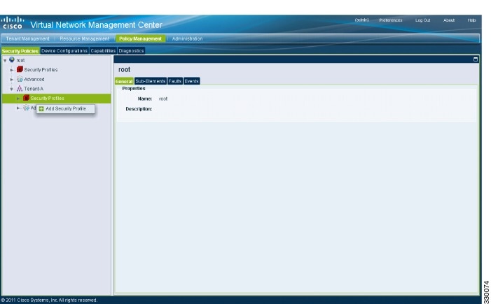
Step 2 ![]() From the directory path, choose Security Policies > root > Tenant-A > Security Profiles. Right-click in an empty space and from the drop-down list, choose Add Security Profile.
From the directory path, choose Security Policies > root > Tenant-A > Security Profiles. Right-click in an empty space and from the drop-down list, choose Add Security Profile.
The Add Security Profile dialog box opens. See Figure 2-43.
Figure 2-43 Add Security Profile Dialog Box
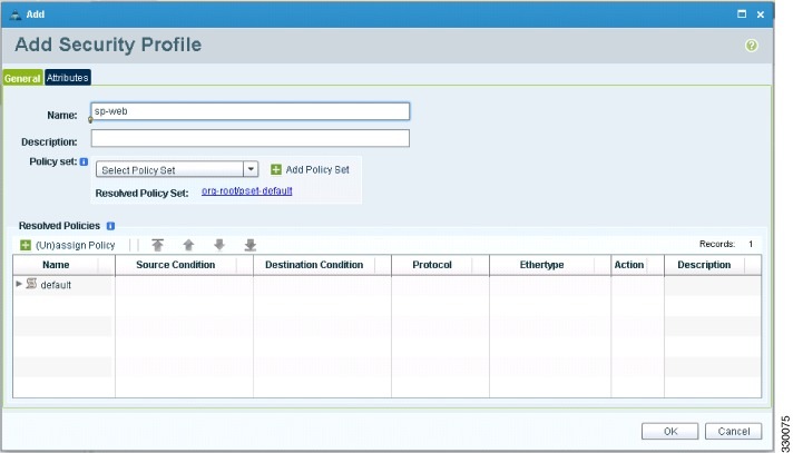
Step 3 ![]() Do the following:
Do the following:
a. ![]() In the Name field, enter a name for the security profile; for example, sp-web.
In the Name field, enter a name for the security profile; for example, sp-web.
b. ![]() In the Description field, enter a brief description of this security profile.
In the Description field, enter a brief description of this security profile.
Step 4 ![]() Click OK.
Click OK.
On the Cisco VNMC, Configuring a Compute Firewall
The compute firewall is a logical virtual entity that contains the device profile that you can bind (assign) to a Cisco VSG virtual machine. The device policy in the device profile is then pushed from the Cisco VNMC to the Cisco VSG. Once this is complete, the compute firewall is in the applied configuration state on the Cisco VNMC.
PROCEDURE
Step 1 ![]() From the Cisco VNMC, choose Resource Management > Managed Resources.
From the Cisco VNMC, choose Resource Management > Managed Resources.
The VNMC Resource Management, Managed Resources, Firewall Profiles window opens. See Figure 2-44.
Figure 2-44 VNMC Resource Management, Managed Resources, Firewall Profiles Window
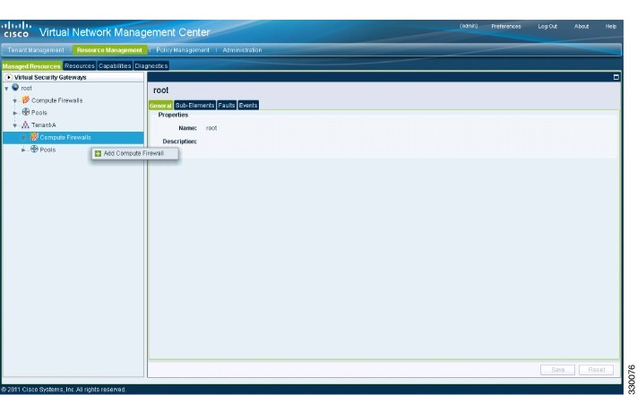
Step 2 ![]() On the left-pane directory tree, choose root > Tenant-A > Compute Firewall.
On the left-pane directory tree, choose root > Tenant-A > Compute Firewall.
Step 3 ![]() From the drop-down list, choose Add Compute Firewall.
From the drop-down list, choose Add Compute Firewall.
The Add Compute Firewall dialog box opens. See Figure 2-45.
Figure 2-45 Add Compute Firewall Dialog Box
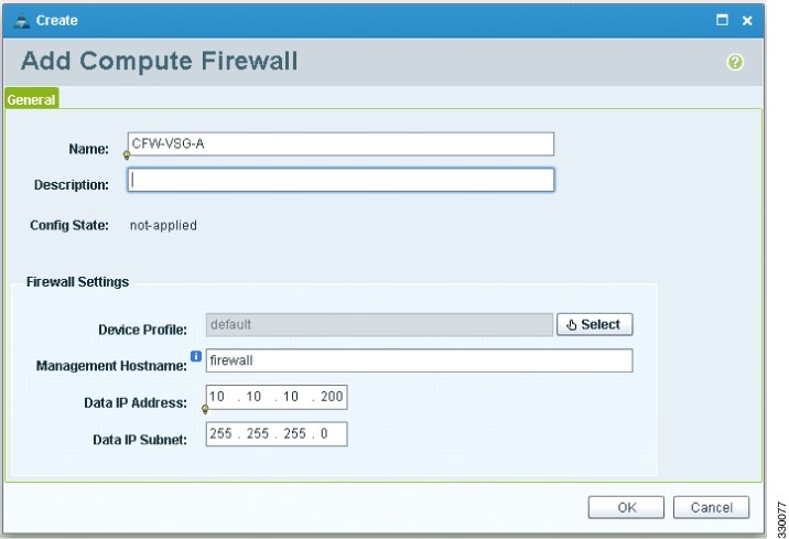
Step 4 ![]() In the Add Compute Firewall dialog box, do the following:
In the Add Compute Firewall dialog box, do the following:
•![]() In the Name field, enter a name for the compute firewall.
In the Name field, enter a name for the compute firewall.
•![]() In the Decription field, enter a brief description of the compute firewall.
In the Decription field, enter a brief description of the compute firewall.
•![]() In the Management Hostname field, enter the name for your Cisco VSG.
In the Management Hostname field, enter the name for your Cisco VSG.
•![]() In the Data IP Address field, enter the Data IP address, if it is different from what is the default.
In the Data IP Address field, enter the Data IP address, if it is different from what is the default.
Step 5 ![]() Click OK.
Click OK.
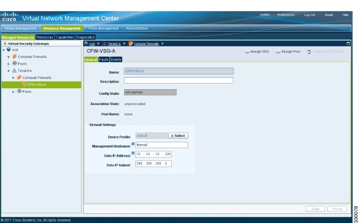
The new Compute Firewall pane displays with the information that you provided. See Figure 2-46.
Figure 2-46 Compute Firewall Pane
Task 8—On the Cisco VNMC, Assigning the Cisco VSG to the Compute Firewall
The compute firewall is a logical virtual entity that contains the device profile that can be later bound to the device for communication with the Cisco VNMC and VSM.
You can assign the Cisco VSG to the compute firewall on the Cisco VNMC.
PROCEDURE
Step 1 ![]() Choose Resource Management > Managed Resources.
Choose Resource Management > Managed Resources.
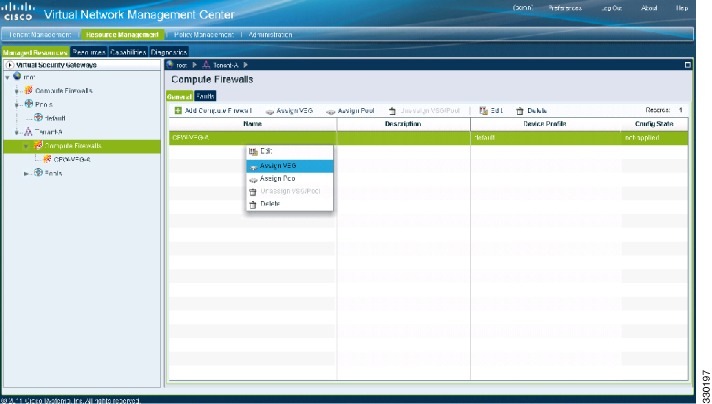
The VNMC Resource Management Managed Resources Compute Firewalls window opens. See Figure 2-47.
Figure 2-47 VNMC Resource Management Managed Resources Compute Firewalls Window
Step 2 ![]() Choose root > Tenant-A > Compute Firewalls.
Choose root > Tenant-A > Compute Firewalls.
Step 3 ![]() Right-click Compute Firewalls, and from the drop-down list, choose Assign VSG.
Right-click Compute Firewalls, and from the drop-down list, choose Assign VSG.
The Assign VSG dialog box opens. See Figure 2-48.
Figure 2-48 Assign VSG Dialog Box
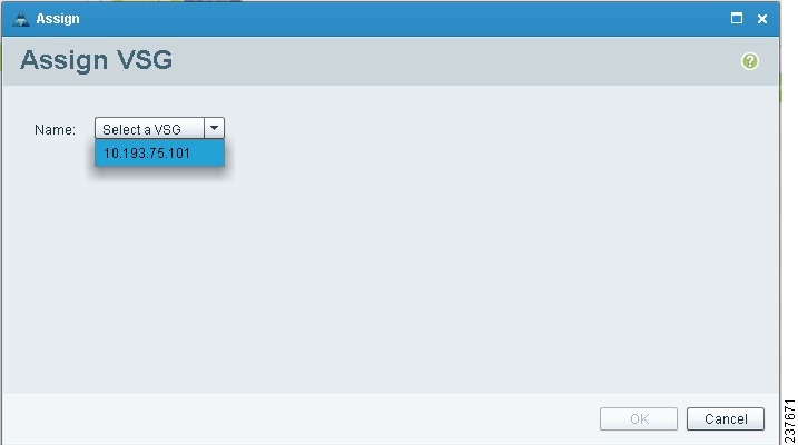
Step 4 ![]() From the Name drop-down list, choose the Cisco VSG IP address.
From the Name drop-down list, choose the Cisco VSG IP address.
Step 5 ![]() Click OK.
Click OK.
Note ![]() The Config State status changes from "not-applied" to "applying" and then to "applied."
The Config State status changes from "not-applied" to "applying" and then to "applied."
Task 9—On the Cisco VNMC, Configuring a Permit-All Rule
You can configure a permit-all rule in the Cisco VNMC.
PROCEDURE
Step 1 ![]() Log in to the Cisco VNMC and choose Policy Management > Security Policies.
Log in to the Cisco VNMC and choose Policy Management > Security Policies.
The Cisco VNMC Policy Management Security Policies window opens. See Figure 2-49.
Figure 2-49 Cisco Virtual Network Management Center—Policy Management Security Policies Window
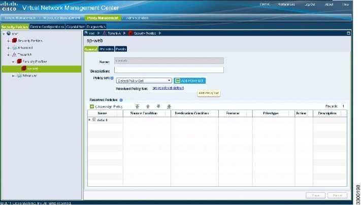
Step 2 ![]() Choose root > Tenant-A > Security-Profile > sp-web.
Choose root > Tenant-A > Security-Profile > sp-web.
Step 3 ![]() From the button to the right of the sp-web pane Policy sets field, click Add policy set.
From the button to the right of the sp-web pane Policy sets field, click Add policy set.
The Add Policy Set dialog box opens. See Figure 2-50.
Figure 2-50 Add Policy Set Dialog Box
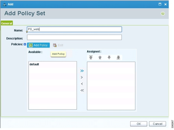
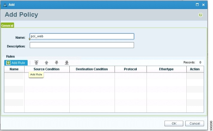
Step 4 ![]() Click Add Policy. The Add Policy dialog box appears. See Figure 2-51.
Click Add Policy. The Add Policy dialog box appears. See Figure 2-51.
Figure 2-51 Add Policy Dialog Box
Step 5 ![]() Do the following:
Do the following:
a. ![]() In the Name field, enter the security policy name.
In the Name field, enter the security policy name.
b. ![]() In the Description field, enter a brief description of the security policy.
In the Description field, enter a brief description of the security policy.
c. ![]() Above the Name column, click Add Rule.
Above the Name column, click Add Rule.
The Add Rule dialog box displays. See Figure 2-52.
Figure 2-52 VNMC Add Rule Dialog Box

Step 6 ![]() In the Name field, enter the rule name.
In the Name field, enter the rule name.
Step 7 ![]() In the Description field, enter a brief description of the rule.
In the Description field, enter a brief description of the rule.
Step 8 ![]() From the Action to Take buttons, choose the rule action that you want this rule to have; in this case, permit.
From the Action to Take buttons, choose the rule action that you want this rule to have; in this case, permit.
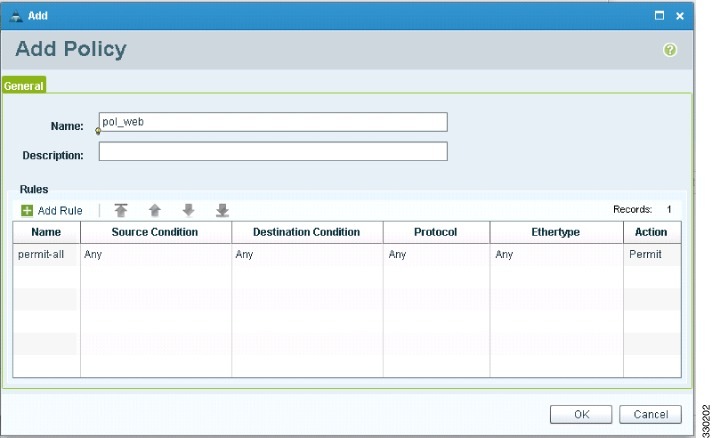
Step 9 ![]() Click OK in this Add Rule dialog box.
Click OK in this Add Rule dialog box.
The Add Policy dialog box reappears showing a policy with the new rule. See Figure 2-53.
Figure 2-53 VNMC Add Policy Dialog Box
Step 10 ![]() Click OK in the Add Policy dialog box.
Click OK in the Add Policy dialog box.
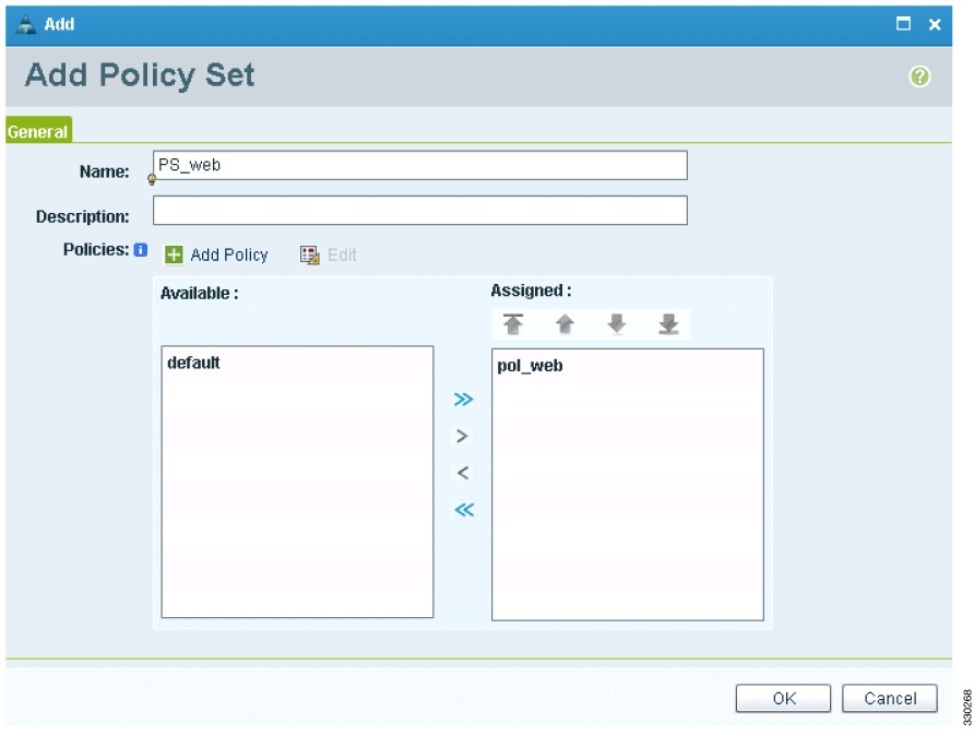
Step 11 ![]() Click OK in the Add Policy Set dialog box. The newly created policy is displayed in the Assigned: field. See Figure 2-54.
Click OK in the Add Policy Set dialog box. The newly created policy is displayed in the Assigned: field. See Figure 2-54.
Figure 2-54 Add Policy Set Dialog Box
Step 12 ![]() Click OK in the Add Policy Set dialog box.
Click OK in the Add Policy Set dialog box.
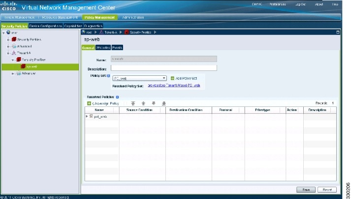
Step 13 ![]() Click Save in the Security Profile window. See Figure 2-55.
Click Save in the Security Profile window. See Figure 2-55.
Figure 2-55 Cisco Virtual Network Management Center—Policy Management Window
Task 10—On the Cisco VSG, Verifying the Permit-All Rule
To verify the rule presence in the Cisco VSG, use the Cisco VSG CLI and the show commands.
PROCEDURE
Step 1 ![]() Log in to the Cisco VSG and enter the following commands:
Log in to the Cisco VSG and enter the following commands:
vsg# show running-config | begin security
security-profile default@root
policy default@root
custom-attribute vnsporg "root"
security-profile sp-web@root/Tenant-A
policy PS_web@root/Tenant-A
custom-attribute vnsporg "root/Tenant-A"
rule default/default-rule@root
action 10 drop
rule pol_web/permit-all@root/Tenant-A
action 10 log
action 11 permit
policy default@root
rule default/default-rule@root order 2
policy PS_web@root/Tenant-A
rule pol_web/permit-all@root/Tenant-A order 101
Task 11—Enabling Logging
This section includes the following topics:
•![]() Enabling Logging Level 6 for Policy-Engine Logging
Enabling Logging Level 6 for Policy-Engine Logging
•![]() Enabling Global Policy-Engine Logging
Enabling Global Policy-Engine Logging
Enabling Logging Level 6 for Policy-Engine Logging
Logging enables you to see what traffic is going through your monitored virtual machine. This logging is helpful for verifying that you have a proper configuration and to help in troubleshooting.
You can enable Logging Level 6 for policy-engine logging in a monitor sesson.
PROCEDURE
Step 1 ![]() Log in to the Cisco VNMC.
Log in to the Cisco VNMC.
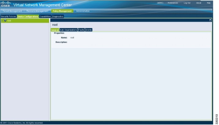
Step 2 ![]() Choose Policy Management > Device Configurations. See Figure 2-56.
Choose Policy Management > Device Configurations. See Figure 2-56.
Figure 2-56 Cisco Virtual Network Management Center—Device Configurations Window
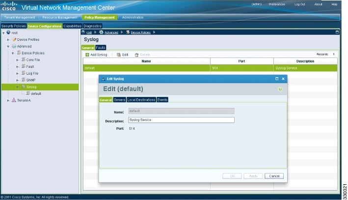
Step 3 ![]() From the left pane navigation tree, choose root > Advanced > Device Policies > Syslog.
From the left pane navigation tree, choose root > Advanced > Device Policies > Syslog.
Step 4 ![]() From the Syslog panel on the right, choose Default and click Edit.
From the Syslog panel on the right, choose Default and click Edit.
Figure 2-57 Cisco Virtual Network Management Center Syslog Pane Edit Syslog Dialog Box
Step 5 ![]() Click on Servers tab. See Figure 2-58.
Click on Servers tab. See Figure 2-58.
Figure 2-58 Cisco Virtual Network Management Center Edit Syslog Dialog Box
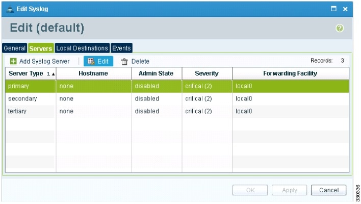
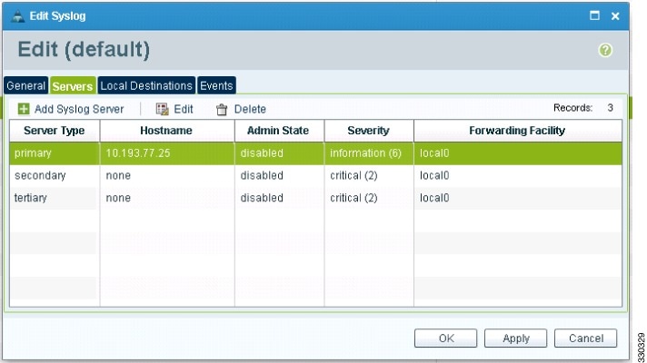
Step 6 ![]() From the Server Type column, choose the primary server type from the displayed list and from the pane toolbar, click Edit. See Figure 2-59.
From the Server Type column, choose the primary server type from the displayed list and from the pane toolbar, click Edit. See Figure 2-59.
Figure 2-59 Edit Syslog Server Dialog Box
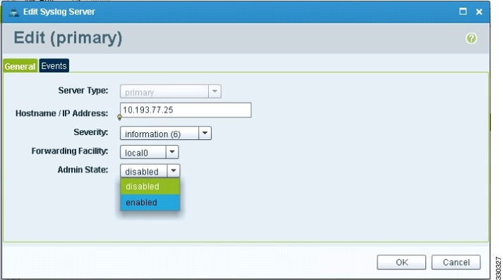
Step 7 ![]() In the Hostname/IP address field, enter the syslog server IP address.
In the Hostname/IP address field, enter the syslog server IP address.
Step 8 ![]() From the Severity drop-down list, choose Information(6).
From the Severity drop-down list, choose Information(6).
Step 9 ![]() From the Admin State drop-down list, choose Enabled.
From the Admin State drop-down list, choose Enabled.
Step 10 ![]() Click OK.
Click OK.
Figure 2-60 Edit Syslog Dialog Box
Step 11 ![]() Click OK.
Click OK.
Enabling Global Policy-Engine Logging
Logging enables you to see what traffic is going through your monitored virtual machine. This logging is helpful for verifying that you have a proper configuration and to help in troubleshooting.
You can enable global policy-engine logging.
PROCEDURE
Step 1 ![]() Log in to the Cisco VNMC and choose Policy Management > Device Configurations > root > Device Profiles > default.
Log in to the Cisco VNMC and choose Policy Management > Device Configurations > root > Device Profiles > default.
The Cisco VNMC Policy Management window opens.
Step 2 ![]() In the Device Profiles pane, choose Policies. See Figure 2-61.
In the Device Profiles pane, choose Policies. See Figure 2-61.
Figure 2-61 Cisco Virtual Network Management Center Policy Management Device Configurations Profiles Pane
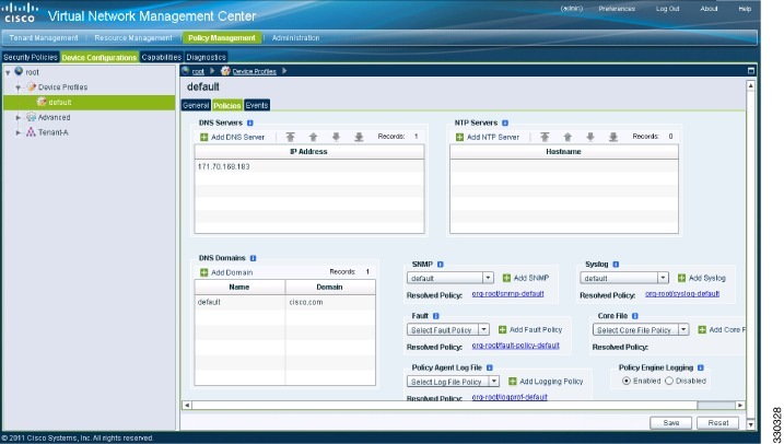
Step 3 ![]() In the Policy Engine Logging area at the bottom of the pane, click Enabled.
In the Policy Engine Logging area at the bottom of the pane, click Enabled.
Step 4 ![]() Click Save to save the configuration.
Click Save to save the configuration.
Task 12—Enabling the Traffic VM's Port-Profile for Firewall Protection and Verifying the Communication Between the VSM, VEM, and VSG
This section includes the following topics:
•![]() Enabling Traffic VM's Port-Profile for Firewall Protection
Enabling Traffic VM's Port-Profile for Firewall Protection
•![]() Verifying the VSM/VEM for Cisco VSG Reachability
Verifying the VSM/VEM for Cisco VSG Reachability
•![]() Checking the VM Veth Port for Firewall Protection
Checking the VM Veth Port for Firewall Protection
BEFORE YOU BEGIN
Make sure you have the following:
•![]() Cisco VSG data IP (10.10.10.200) and VLAN ID (100)
Cisco VSG data IP (10.10.10.200) and VLAN ID (100)
•![]() Security profile name (for example, sp-web)
Security profile name (for example, sp-web)
•![]() Organization (Org) name (for example, root/Tenant-A)
Organization (Org) name (for example, root/Tenant-A)
•![]() The port-profile that you would like to edit to enable firewall protection
The port-profile that you would like to edit to enable firewall protection
Enabling Traffic VM's Port-Profile for Firewall Protection
This example shows the traffic VM port profile before firewall protection:
port-profile type vethernet pp-webserver
vmware port-group
switchport mode access
switchport access vlan 3770
no shutdown
state enabled
This example shows how to enable firewall protection:
vsm(config)# port-profile pp-webserver
vsm(config-port-prof)# vn-service ip-address 10.10.10.200 vlan 100 security-profile sp-web
vsm(config-port-prof)# org root/Tenant-A
This example shows the traffic VM port profile after firewall protection:
port-profile type vethernet pp-webserver
vmware port-group
switchport mode access
switchport access vlan 3770
vn-service ip-address 10.10.10.200 vlan 100 security-profile sp-web
org root/Tenant-A
no shutdown
state enabled
Verifying the VSM/VEM for Cisco VSG Reachability
This example show how to verify VEM/VSG communication:
vsm# show vsn brief
VLAN IP-ADDR MAC-ADDR FAIL-MODE STATE MODULE
100 10.10.10.200 00:50:56:83:00:46 Close Up 3
vsm#
A display showing the MAC-ADDR Listing and Up state verifies that the VEM can communicate with the Cisco VSG.
Checking the VM Veth Port for Firewall Protection
This example shows how to verify the VM Veth port for firewall protection:
vsm# show vsn port vethernet16
Veth : Veth16
VM Name : sg-allrun-centos2
VM uuid : 42 03 d1 ab 29 20 fd 01-57 89 80 1a 6f fe 04 8b
DV Port : 2112
DVS uuid : 40 f2 03 50 4b b3 50 eb-2e 13 bc 0c 82 ee 54 58
Flags : 0x148
VSN Data IP : 10.10.10.200
Security Profile : sp-web
Org : root/Tenant-A
VNSP id : 2
IP addresses:
172.31.2.92
Note ![]() Make sure that your VNSP ID value is more than 1.
Make sure that your VNSP ID value is more than 1.
Task 13—Sending Traffic Flow and on the Cisco VSG Verifying Statistics and Logs
This section includes the following topics:
•![]() On the Cisco VSG, Verifying Policy-Engine Statistics and Logs
On the Cisco VSG, Verifying Policy-Engine Statistics and Logs
Sending Traffic Flow
You can send traffic flow through the Cisco VSG to ensure that it is functioning properly.
PROCEDURE
Step 1 ![]() Ensure that you have the VM (Server-VM) that is using the port profile (pp-webserver) configured for firewall protection. See Figure 2-62.
Ensure that you have the VM (Server-VM) that is using the port profile (pp-webserver) configured for firewall protection. See Figure 2-62.
Figure 2-62 Virtual Machine Properties Window
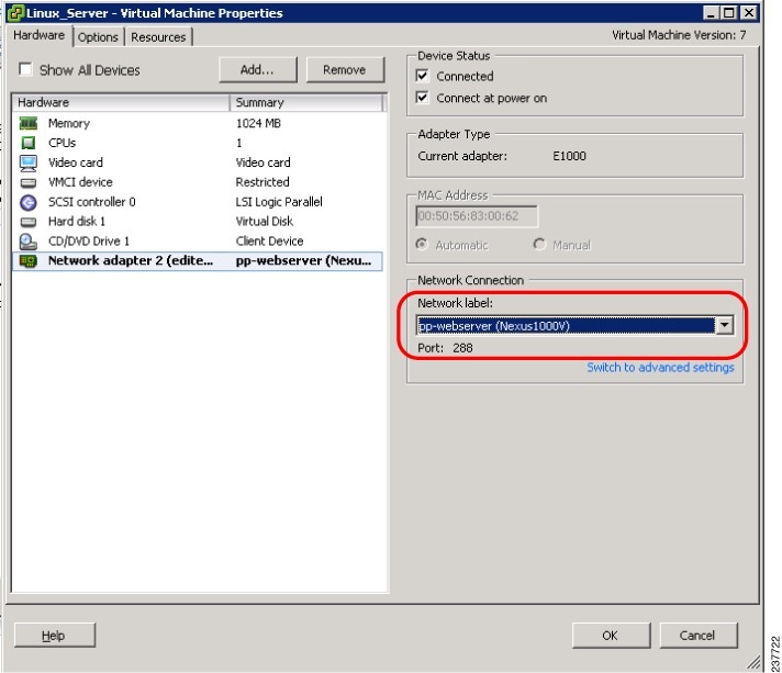
Step 2 ![]() Log in to any of your client VM (Client-VM) and send traffic (for example, HTTP) to your Server-VM.
Log in to any of your client VM (Client-VM) and send traffic (for example, HTTP) to your Server-VM.
[root@sg-centos-vk1 ~]# wget http://172.31.2.92/
--2010-11-28 13:38:40-- http://172.31.2.92/
Connecting to 172.31.2.92:80... connected.
HTTP request sent, awaiting response... 200 OK
Length: 258 [text/html]
Saving to: `index.html'
100%[=======================================================================>] 258
--.-K/s   in 0s
2010-11-28 13:38:40 (16.4 MB/s) - `index.html' saved [258/258]
[root@sg-centos-vk1 ~]#
Step 3 ![]() Check the policy-engine statistics and log on the Cisco VSG.
Check the policy-engine statistics and log on the Cisco VSG.
On the Cisco VSG, Verifying Policy-Engine Statistics and Logs
Log in to the Cisco VSG and check the policy-engine statistics and logs.
This example shows how to check the policy-engine statistics and logs:
vsg# show policy-engine stats
Policy Match Stats:
default@root : 0
default/default-rule@root : 0 (Drop)
NOT_APPLICABLE : 0 (Drop)
PS_web@root/Tenant-A : 1
pol_web/permit-all@root/Tenant-A : 1 (Log, Permit)
NOT_APPLICABLE : 0 (Drop)
vsg# terminal monitor
vsg# 2010 Nov 28 05:41:27 firewall %POLICY_ENGINE-6-POLICY_LOOKUP_EVENT:
policy=PS_web@root/Tenant-A rule=pol_web/permit-all@root/Tenant-A action=Permit
direction=egress src.net.ip-address=172.31.2.91 src.net.port=48278
dst.net.ip-address=172.31.2.92 dst.net.port=80 net.protocol=6 net.ethertype=800
 Feedback