Cisco Nexus 7000 Series NX-OS Virtual Device Context Configuration Guide
Bias-Free Language
The documentation set for this product strives to use bias-free language. For the purposes of this documentation set, bias-free is defined as language that does not imply discrimination based on age, disability, gender, racial identity, ethnic identity, sexual orientation, socioeconomic status, and intersectionality. Exceptions may be present in the documentation due to language that is hardcoded in the user interfaces of the product software, language used based on RFP documentation, or language that is used by a referenced third-party product. Learn more about how Cisco is using Inclusive Language.
- Updated:
- February 28, 2013
Chapter: Managing VDCs
Managing VDCs

Note![]() See the Cisco NX-OS FCoE Configuration Guide for Cisco Nexus 7000 and Cisco MDS 9500 Guide for information on allocating interfaces for storage VDCs and FCoE.
See the Cisco NX-OS FCoE Configuration Guide for Cisco Nexus 7000 and Cisco MDS 9500 Guide for information on allocating interfaces for storage VDCs and FCoE.
Note![]() Beginning with Cisco NX-OS Release 5.2(1) for Nexus 7000 Series devices, all members of a port group are automatically allocated to the VDC when you allocate an interface.
Beginning with Cisco NX-OS Release 5.2(1) for Nexus 7000 Series devices, all members of a port group are automatically allocated to the VDC when you allocate an interface.
The following Cisco Nexus 7000 Series Ethernet modules have the following number of port groups and interfaces:
- N7K-M202CF-22L (1 interface x 2 port groups = 2 interfaces)—There are no restrictions on the interface allocation between VDCs.
- N7K-M206FQ-23L (1 interface x 6 port groups = 6 interfaces)—There are no restrictions on the interface allocation between VDCs.
- N7K-M224XP-23L (1 interface x 24 port groups = 24 interfaces)—There are no restrictions on the interface allocation between VDCs.
- N7K-M108X2-12L (1 interface x 8 port groups = 8 interfaces)—There are no restrictions on the interface allocation between VDCs.
- N7K-M148GS-11 (12 interfaces x 4 port groups = 48 interfaces), N7K-M148GS-11L, N7K-M148GT-11, N7K-M148GT-11L (same as non-L M148) (1interface x 48 port groups = 48 interfaces) —There are no restrictions on the interface allocation between VDCs, but we recommend that interfaces that belong to the same port group be in a single VDC.
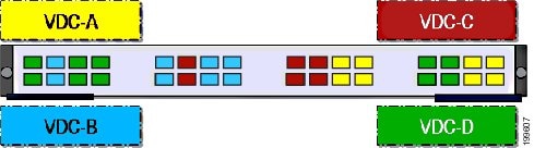
N7K-M132XP-12 (4 interfaces x 8 port groups = 32 interfaces) and N7K-M132XP-12L (same as non-L M132) (1 interface x 8 port groups = 8 interfaces)—All M132 cards require allocation in groups of 4 ports and you can configure 8 port groups. Interfaces belonging to the same port group must belong to the same VDC. See the example for this module in(2 interfaces x 16 port groups = 32 interfaces). Interfaces that belong to the same port group must belong to the same VDC (see Figure 1-1).
Note![]() You can configure the limit-resource module-type command only from the VDC configuration mode and not from a VDC resource template.
You can configure the limit-resource module-type command only from the VDC configuration mode and not from a VDC resource template.
Figure 1-1 Example Interface Allocation for Port Groups on the Cisco Nexus 7000 Series 10-Gbps Ethernet Module N7K-F132XP-15
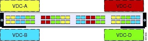
(4 interfaces x 12 port groups = 48 interfaces). Interfaces that belong to the same port group must belong to the same VDC (see Figure 1-2).
Figure 1-2 Example Interface Allocation for Port Groups on the Cisco Nexus 7000 Series 10-Gbps Ethernet Modules N7K-F248XP-25[E] and N7K-F248XT-25[E] and Cisco Nexus 7700 Series 48-Port 1 and 10-Gbps Ethernet Module N77-F248XP-23E
When interfaces in different VDCs share the same port ASIC, reloading the VDC (with the reload vdc command) or provisioning interfaces to the VDC (with the allocate interface command) might cause short traffic disruptions (of 1 to 2 seconds) for these interfaces. If such behavior is undesirable, make sure to allocate all interfaces on the same port ASIC to the same VDC.
This example shows how to map interfaces to the port ASIC:
The interface number is listed in the FP port column, and the port ASIC number is listed in the MAC_0 column, which means that in the above example, interfaces 1 through 12 share the same port ASIC (0).

MAC Addresses
The default VDC has a management MAC address. Beginning with Cisco NX-OS Release 5.2(1) for the Cisco Nexus 7000 Series devices, subsequent nondefault VDCs that you create are assigned MAC addresses automatically as part of the bootup process.
You will see a syslog message if there are not sufficient MAC addresses to supply all the VDCs on the device.
- followed by If sufficient MAC addresses to program the management port of all the nondefault VDCs are unavailable, do not program the MAC address in any of the nondefault VDCs.
- A syslog message is generated if sufficient MAC addresses are unavailable to program the management port in all VDCs.
- When a hardware issue occurs, syslog messages are sent to all VDCs.
- When you have back-to-back connected interfaces in two different virtual routing and forwarding (VRF) instances within the same VDC, the Address Resolution Protocol (ARP) fails to complete and packet drops occur because the VRFs obtain their own source MAC addresses. If you need two interfaces on the same VDC with different VRFs, assign a static MAC address to the VRF interfaces.
Note![]() See the Cisco NX-OS FCoE Configuration Guide for Cisco Nexus 7000 and Cisco MDS 9500 for information on allocating interfaces to storage VDCs for Fibre Channel over Ethernet (FCoE).
See the Cisco NX-OS FCoE Configuration Guide for Cisco Nexus 7000 and Cisco MDS 9500 for information on allocating interfaces to storage VDCs for Fibre Channel over Ethernet (FCoE).
Note![]() Beginning with Cisco NX-OS Release 5.2(1) for Nexus 7000 Series devices, all members of a port group are automatically allocated to the VDC when you allocate an interface.
Beginning with Cisco NX-OS Release 5.2(1) for Nexus 7000 Series devices, all members of a port group are automatically allocated to the VDC when you allocate an interface.
Beginning with Cisco NX-OS Release 6.1, CPU shares are used to control the CPU resources among the VDCs by allowing you to prioritize VDC access to the CPU during CPU contention. CPU shares are supported on Supervisor 2/2e modules only. You can also configure the number of CPU shares on a VDC. For example, a VDC with 10 CPU shares gets twice the CPU time compared to a VDC that has 5 CPU shares.
Some features require that all modules in a chassis be of a certain type. Beginning with Cisco NX-OS Release 6.1(3), you can apply the switchwide VDC mode to prevent accidental insertion of a module or to restrict certain line cards from powering on in the system. For example, the result bundle hashing (RBH) modulo feature does not operate with M Series modules in the system. Use the system module-type command to apply the switchwide VDC mode. This command controls which line cards are allowed in the chassis (see Table 1-1 ). Otherwise, widespread disruption is caused within a VDC.
Note![]() The modules that you do not enable must not be powered on after you configure this feature and enter yes. An error message forces you to manually disable these modules before proceeding, which prevents major disruptions and service issues within a VDC.
The modules that you do not enable must not be powered on after you configure this feature and enter yes. An error message forces you to manually disable these modules before proceeding, which prevents major disruptions and service issues within a VDC.
Beginning with Cisco NX-OS Release 6.2(2), the F2e Series module can be enabled on the chassis, which now allows interoperability with the M Series modules. For a chassis with only F2e Series modules, the default VDC will be created using an F2e Series module as a supported module unless you apply your own configuration. F2 Series modules are only compatible with F2e Series modules on the chassis. The F2e and F2 Series modules cannot exist with the F1 Series module in the same VDCs. Currently, only F1, F2, and F2e Series modules are supported by storage VDCs. While Supervisor 1 supports only F1 Series modules in a storage VDC, Supervisor 2/2e supports all these types. The rules of mixing module types in a storage VDC is the same as in an ethernet VDC. (See Table 1-1 and Table 1-2 for information on restrictions and conditions of allowed module type mixes within VDCs).
Note![]() When using the system module-type command to apply the switchwide VDC mode, there are no restrictions on the module types that can be mixed
When using the system module-type command to apply the switchwide VDC mode, there are no restrictions on the module types that can be mixed
|
|
|
|
|
|---|---|---|---|
|
|
|||
|
|
|||
|
|
Note![]() For Cisco NX-OS Release 6.1 only, because F2e Series modules are supported as F2 Series modules, F2e Series modules follow the same mixing rules as F2 Series modules.
For Cisco NX-OS Release 6.1 only, because F2e Series modules are supported as F2 Series modules, F2e Series modules follow the same mixing rules as F2 Series modules.
Note![]() Storage VDCs in Cisco NX-OS Release 6.2(6) do not support F3 Series modules.
Storage VDCs in Cisco NX-OS Release 6.2(6) do not support F3 Series modules.
|
|
|
||||||
|
|
|||||||
|
|
|||||||
|
|
|
||||||
|
|
|
||||||
|
|
|||||||
|
|
|||||||
|
|
Note![]() F3 F2E M2XL cannot coexist in the same VDC (although any two of them can coexist).
F3 F2E M2XL cannot coexist in the same VDC (although any two of them can coexist).
Table 1-3 Module Type Support on a Default VDC
Note![]() The Cisco Nexus 7710 switch and Cisco Nexus 7718 switch supports F2e and F3 Series module types in both an Ethernet VDC and Storage VDC. F3 Series modules do not support storage VDCs in Cisco NX-OS Release 6.2(6).
The Cisco Nexus 7710 switch and Cisco Nexus 7718 switch supports F2e and F3 Series module types in both an Ethernet VDC and Storage VDC. F3 Series modules do not support storage VDCs in Cisco NX-OS Release 6.2(6).
F2e Proxy Mode
To support the coexistence of an F2e Series module with an M Series module in the same VDC, the F2e Series module operates in a proxy mode so that all Layer 3 traffic is sent to an M Series module in the same VDC. For F2e proxy mode, having routing adjacencies connected through F2e interfaces with an M1 Series module is not supported. However, routing adjacencies connected through F2e interfaces with an M2 Series module is supported.
You cannot allocate F2e ports as shared interfaces in the storage VDC if the F2e port is in proxy mode in the Ethernet VDC.
Note![]() Beginning with Cisco NX-OS Release 6.2(2), F2e module type can exist with M1, M1XL, and M2XL module types in the same VDC.
Beginning with Cisco NX-OS Release 6.2(2), F2e module type can exist with M1, M1XL, and M2XL module types in the same VDC.
When you enter the limit-resource module-type command and it changes the F2e mode between the old VDC type and the new VDC type, you are prompted to enter the rebind interface command, as shown below:
Table 1-4 shows the VDC type changes that require the rebind interface command:
2.![]() [no] system module-type module-type
[no] system module-type module-type
DETAILED STEPS
 Feedback