Cisco DCNM Web Client Online Help, 10.4(2) Release
Bias-Free Language
The documentation set for this product strives to use bias-free language. For the purposes of this documentation set, bias-free is defined as language that does not imply discrimination based on age, disability, gender, racial identity, ethnic identity, sexual orientation, socioeconomic status, and intersectionality. Exceptions may be present in the documentation due to language that is hardcoded in the user interfaces of the product software, language used based on RFP documentation, or language that is used by a referenced third-party product. Learn more about how Cisco is using Inclusive Language.
- Updated:
- February 25, 2018
Chapter: Border Provisioning Use Case in VXLAN BGP EVPN Fabrics - Multi-Site
Border
Provisioning Use Case in VXLAN BGP EVPN Fabrics - Multi-Site
This chapter explains LAN Fabric border provisioning using EVPN Multi-Site feature.
- Overview
- Prerequisites
- Limitations
- Sample Scenario
- EVPN Multi-Site Configuration
- Deploying Networks and VRF Instances
- Additional References
- Appendix
Overview
This document explains how to connect two Virtual eXtensible Local Area Network (VXLAN) Border Gateway Protocol (BGP) Ethernet VPN (EVPN) fabrics through DCNM using EVPN Multi-Site feature. The EVPN Multi-Site configurations are applied on the Border Gateways (BGWs) of the two fabrics. Apart from VXLAN BGP EVPN fabrics, EVPN Multi-Site also allows you to extend Layer 2 and Layer 3 connectivity to data center networks built with older (legacy) technologies (Spanning Tree Protocol, virtual Port Channel [vPC], Cisco FabricPath, etc).
Prerequisites
-
The EVPN Multi-Site feature requires Cisco Nexus 9000 Series NX-OS Release 7.0(3)I7(1) or later.
-
Familiarity with VXLAN BGP EVPN data center fabric architecture and configuration through DCNM.
-
Fully configured VXLAN BGP EVPN fabrics and connected device (route servers, for example) configurations that are ready to be connected using the EVPN Multi-Site feature.
-
VXLAN BGP EVPN fabrics (and their interconnection) can be configured manually or using Cisco® Data Center Network Manager (DCNM). This document explains the process to connect the fabrics through DCNM. So, you should know how to configure and deploy a VXLAN BGP EVPN fabric through DCNM. For more details, see the LAN Fabric Provisioning section under Configure chapter in Cisco DCNM Web Client Online Help, 10.4(2) Release.
-
 Note | For a detailed explanation on the EVPN Multi-Site feature, see the VXLAN BGP EVPN Multi-Site Design and Deployment document. |
Limitations
Sample Scenario
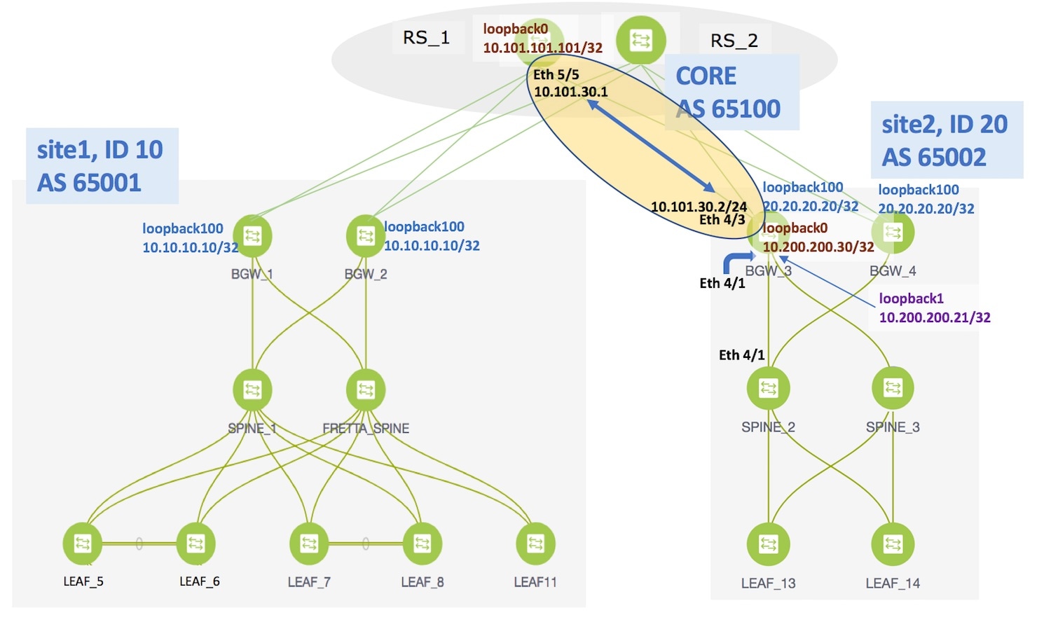
The EVPN Multi-Site feature is explained through an example scenario. Consider two VXLAN BGP EVPN fabrics, site1 and site2. This document will show you how to enable end-to-end Layer 3 and Layer 2 traffic between hosts in site1 and site2.
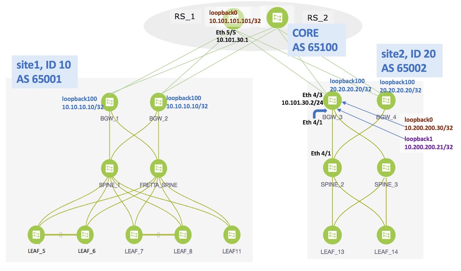
Network configurations for the two fabrics are provisioned through DCNM software, 10.4(2) release. VXLAN BGP EVPN configurations are configured on the switches in the two fabrics. However, server traffic between the sites is only possible through a Data Center Interconnect (DCI) function. If a server in site1 has to send traffic to a server in site2 or vice versa, the DCI function (such as the Multi-Site feature, used for this example) should be configured on the BGWs of both the fabrics.
Note | The DCI functions VRF Lite and VRF Lite + Multi-Site are in the scope of this document, but MPLS L3VPN and LISP technologies are not in the scope of this document. |
-
Top-Down deployment of the underlay for the IP core at the BGWs. This is a one-time configuration.
-
Top-Down deployment of the BGP overlay for the IP core. This is a one-time configuration for each BGW.
-
Deployment of networks/virtual routing and forwarding (VRF) instances on the leaf switches. This is a per network/VRF configuration.
-
Deployment of networks/VRFs at the BGWs. This is a per network/VRF configuration.
EVPN Multi-Site feature—This requires setting up the BGW base configuration for enabling the EVPN Multi-Site feature on the BGWs and the underlay peering to the external devices. This is followed by establishing overlay peering from the BGW to appropriate external devices, either BGWs in other fabrics or route servers. Both the underlay and overlay peering are established over eBGP. BGWs are special devices that allow clear control and data plane segregation from one site to another, allowing for policy enforcement points for any inter-fabric traffic. They allow the same data plane (VXLAN) and control plane (BGP EVPN) to be employed both for inter-fabric and intra-fabric traffic.
Note | DCNM 10.4.2 Top-Down provisioning only supports eBGP underlay. |
-
EVPN Multi-Site configurations on the BGWs (BGW_1, BGW_2, BGW_3 and BGW_4).
-
EVPN Multi-Site feature on the BGWs on site1—Overlay and underlay connections between the BGWs BGW_1 and BGW_2, and directly connected route servers RS_1 and RS_2.
-
EVPN Multi-Site feature on the BGWs on site2—This includes overlay and underlay connections between the BGWs BGW_3 and BGW_4, and directly connected route servers RS_1 and RS_2.
-
Configurations on RS_1 and RS_2—These configurations are not in the scope of DCNM provisioning and this document. For completeness, it is mentioned here, and sample configurations provided in the Appendix section.
For this example, BGW_3 EVPN Multi-Site configurations will be explained.
-
-
Deploying Networks and VRF Instances on the leaf switches and the BGWs
For this example, 2 networks will be configured on the BGWs in site2 (with the assumption that network deployment on leaf switches is already completed).
After successful deployment on both the sites, Layer 2 and Layer 3 traffic will flow between the two sites.
Note | In the DCNM GUI, the lines connecting devices managed by DCNM (for example, LEAF_5 to SPINE_1 and SPINE_1 to BGW_2) symbolize a physical cable connection, and not that the connection is functional and network traffic flows between them. |
To start off with, let us consider EVPN Multi-Site provisioning on BGW_3 through DCNM Top-Down LAN Fabric Provisioning.
EVPN Multi-Site Configuration
Prerequisite Configuration for EVPN Multi-Site Feature
Setting the BGW role to Border Gateway
After configuring the loopback interfaces on the BGWs, you should change the role of each designated BGW to Border Gateway, since, by default a device will be treated as a leaf switch.
To update the switch role, login to DCNM, and click Topology from the main menu at the left part of the screen. In the Topology screen, select the fabric/site from the Scope drop down box (site2 or site1 in this case), and click on the switch icon. A screen pops up with the switch information.
Change the entry from Leaf to Border Gateway as shown in the image.
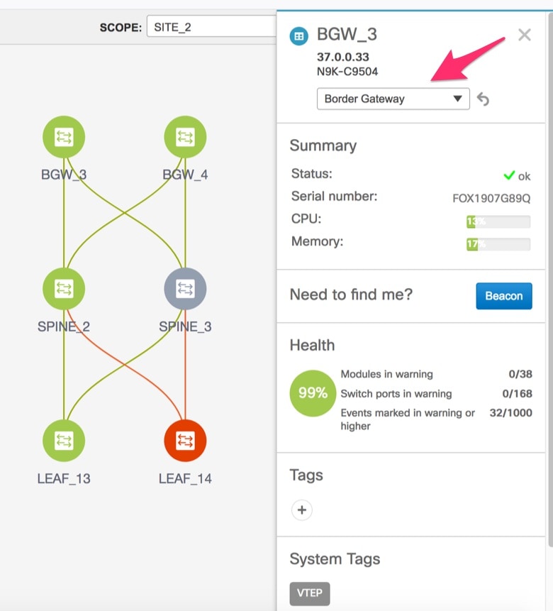
Likewise, update the role for BGW_4 in site2 and then select site1 from the scope box and update roles for BGW_1 and BGW_2. This is required for configuring the EVPN Multi-Site feature through the DCNM GUI.
After completing the EVPN Multi-Site specific prerequisites, start EVPN Multi-Site configuration on BGW_3 with extensions to the route server RS_1.
EVPN Multi-Site Extensions from BGW_3 to RS_1
From the Cisco DCNM Web Client, choose Configure > LAN Fabric Provisioning > Network Deployment. The LAN Fabric Provisioning page appears.
Click Continue. The Select a Fabric page comes up.
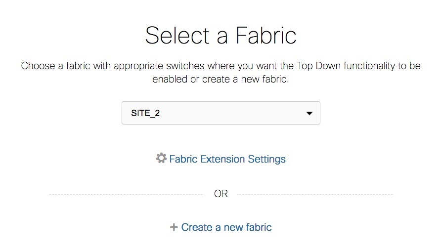
Select site2 from the drop-down box since you are configuring BGW BGW_3 on site2.
Click Fabric Extension Settings since the purpose of this task is to allow site2 to communicate to external fabrics through RS_1 and RS_2. The Fabric Extension screen comes up.
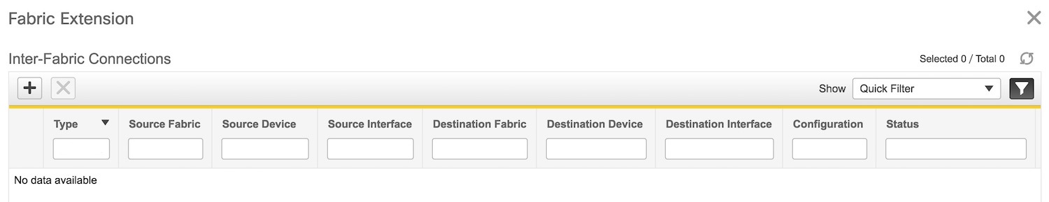
The Inter-Fabric Connections section lists previously created external connections from the BGWs on site2. Each line represents a physical or logical connection between a BGW in site2 and an external device in another fabric. For each connection, the source fabric, source device, source interface, destination fabric, destination device, and destination interface are listed along with the type of external connectivity. This section is empty as this is the first time you are adding an external connection.
To extend the fabric through EVPN Multi-Site, you should first create an underlay extension and then an overlay extension.
Underlay Extension from BGW_3 to RS_1
Click on the + icon to add a new external connection. The Add Inter-Fabric Connection screen appears.
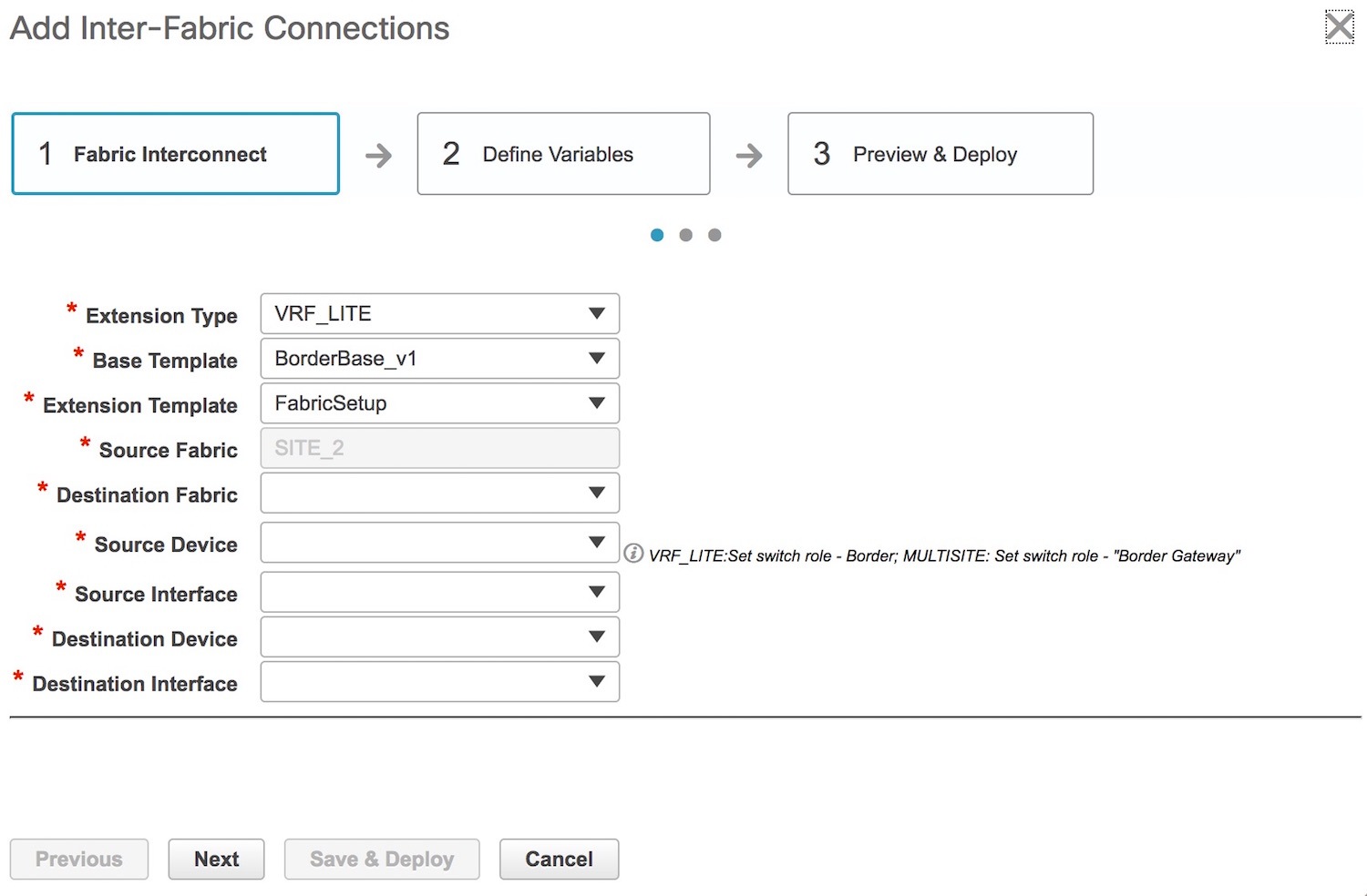
By default, VRF_LITE is populated in the Extension Type field. Change the selection to MULTISITE_UNDERLAY.
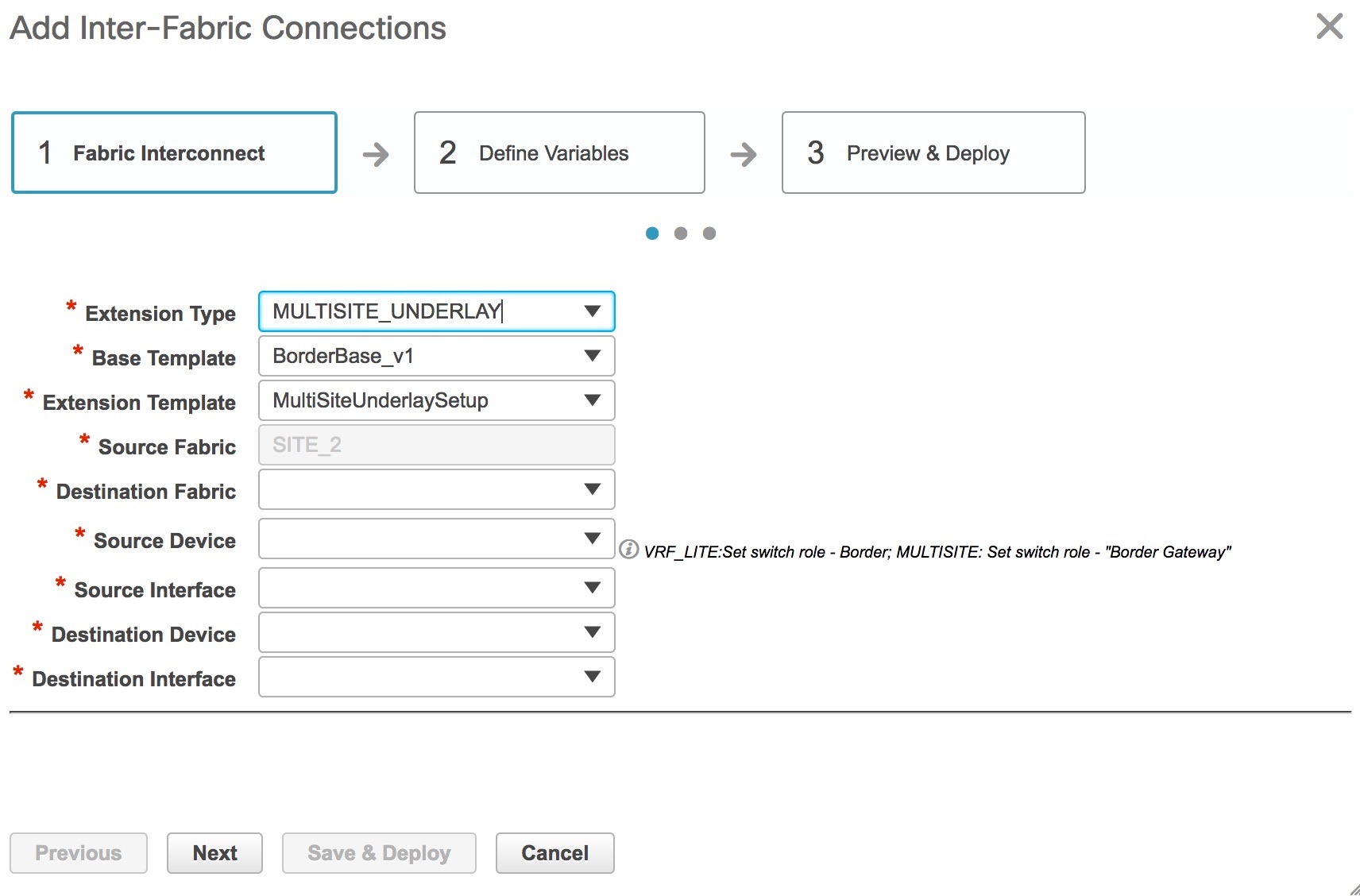
Base Template—By default, the BorderBase_v1 base template is populated. This template is a one-time configuration pushed to the BGW.
Extension Template—MultiSiteUnderlaySetup is a setup template that contains the configuration that will be generated and pushed to the BGW to setup the corresponding inter-fabric connection.
These templates are auto-populated with corresponding pre-packaged default templates based on your selection.
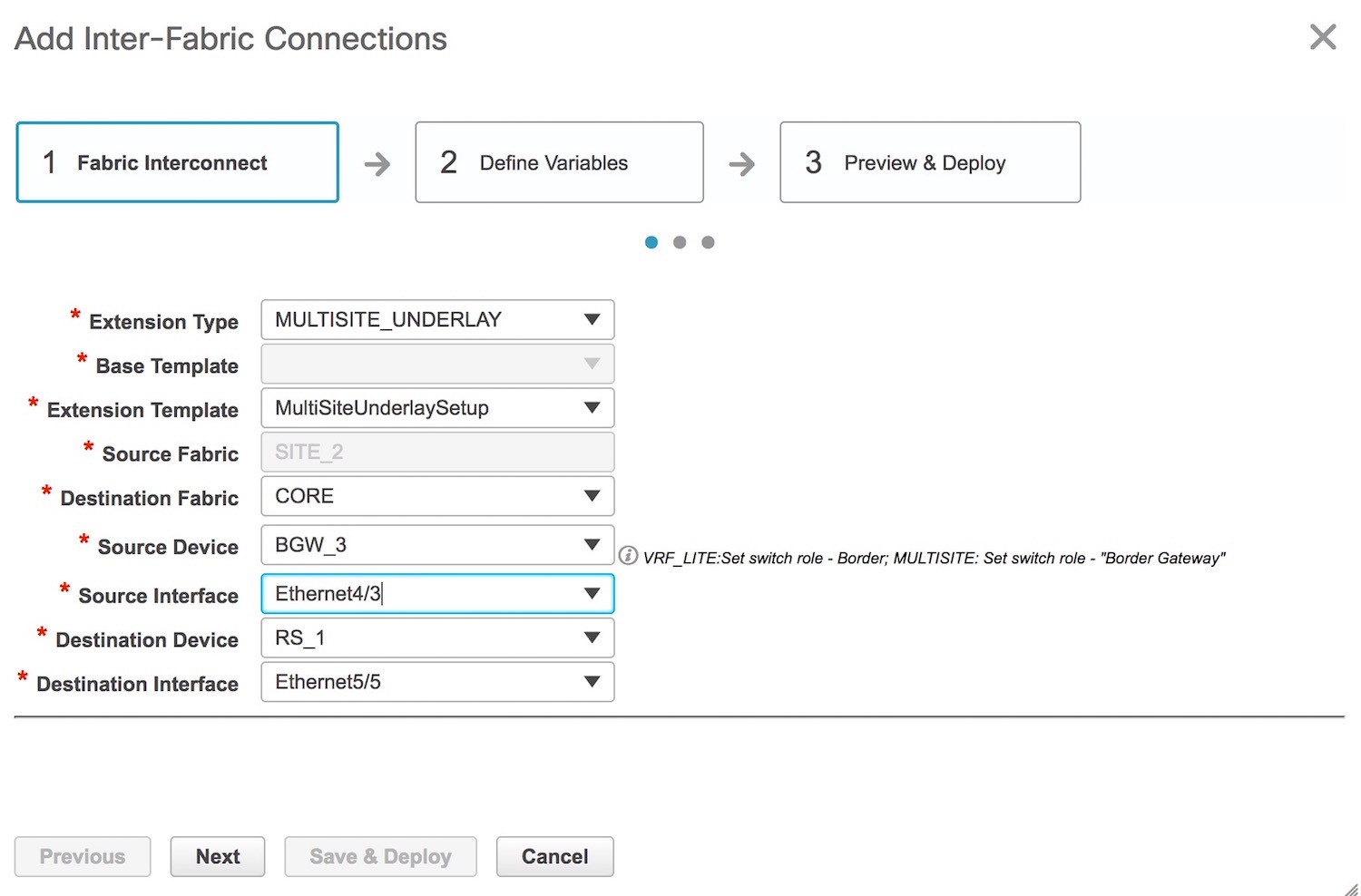
Source Fabric—This field is pre-populated with site2 since the EVPN Multi-Site underlay connection is between BGW_3 in site2 and RS_1 in the CORE fabric.
Destination Fabric—Choose CORE.
Source Device and Source Interface—Choose BGW_3 as the source device and an Ethernet interface that needs to be connected to RS_3.
Destination Device and Destination Interface—Choose RS_1 as the destination device and the Ethernet interface that connects to the BGW BGW_3
Note that based on the selection of the source device and source interface, the destination information will be auto-populated based on Cisco Discovery Protocol information, if available. There is extra validation performed to ensure that the destination external device is indeed part of the destination fabric.
After filling up the Fabric Interconnect section, the screen looks like this.
Click Next to go to the Define Variables section.
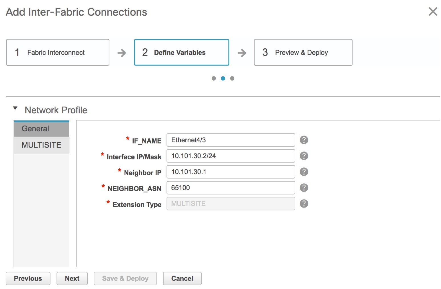
IF_NAME—In this field, the interface name is auto-populated from the previous step.
Interface IP_MASK—Fill up this field with the IP address of the BGW_3 interface that connects to RS_1.
NEIGHBOR_IP—Fill up this field with the IP address of the RS_1 interface that connects to BGW_3.
NEIGHBOR_ASN—In this field, the AS number of RS_1 will be auto-populated.
The corresponding connection in the topology is displayed:
Click the MULTISITE tab.
While the General tab contains external connection details, this tab contains intra-fabric information such as fabric IGP, fabric facing Ethernet interface, etc.
The MULTISITE tab only appears the first time you create an EVPN Multi-Site underlay on a device, since the details remain the same for subsequent connections. The next time you create an EVPN Multi-Site underlay connection, only the General tab will be available.
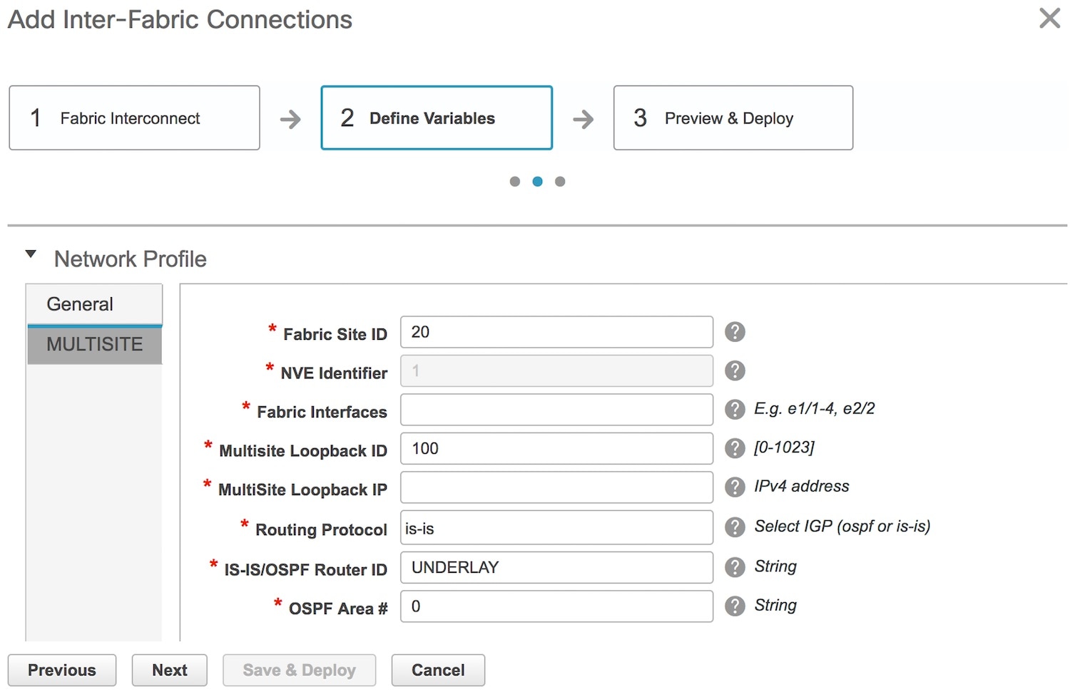
Fabric Site ID—This is the identification for the VXLAN BGP EVPN fabric site2 to which BGW_3 belongs. When you configure the EVPN Multi-Site feature on BGW_4 (or any other BGW on site2), the site ID will be 20. The site site1 will be assigned with a unique ID.
NVE Identifier—This is the VXLAN overlay ID.
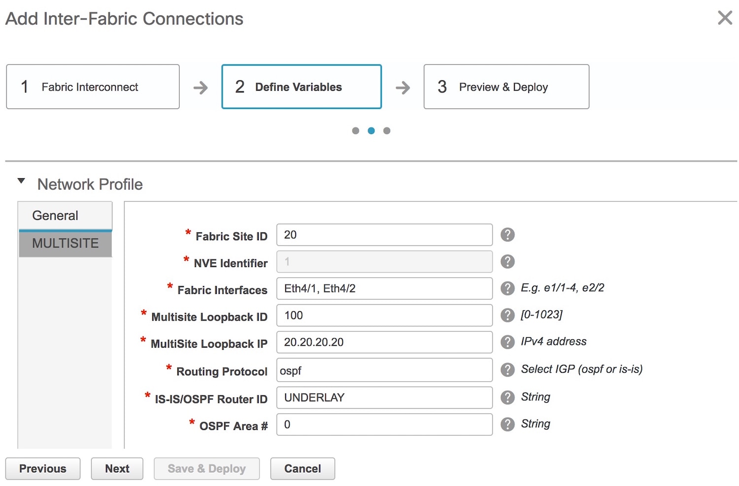
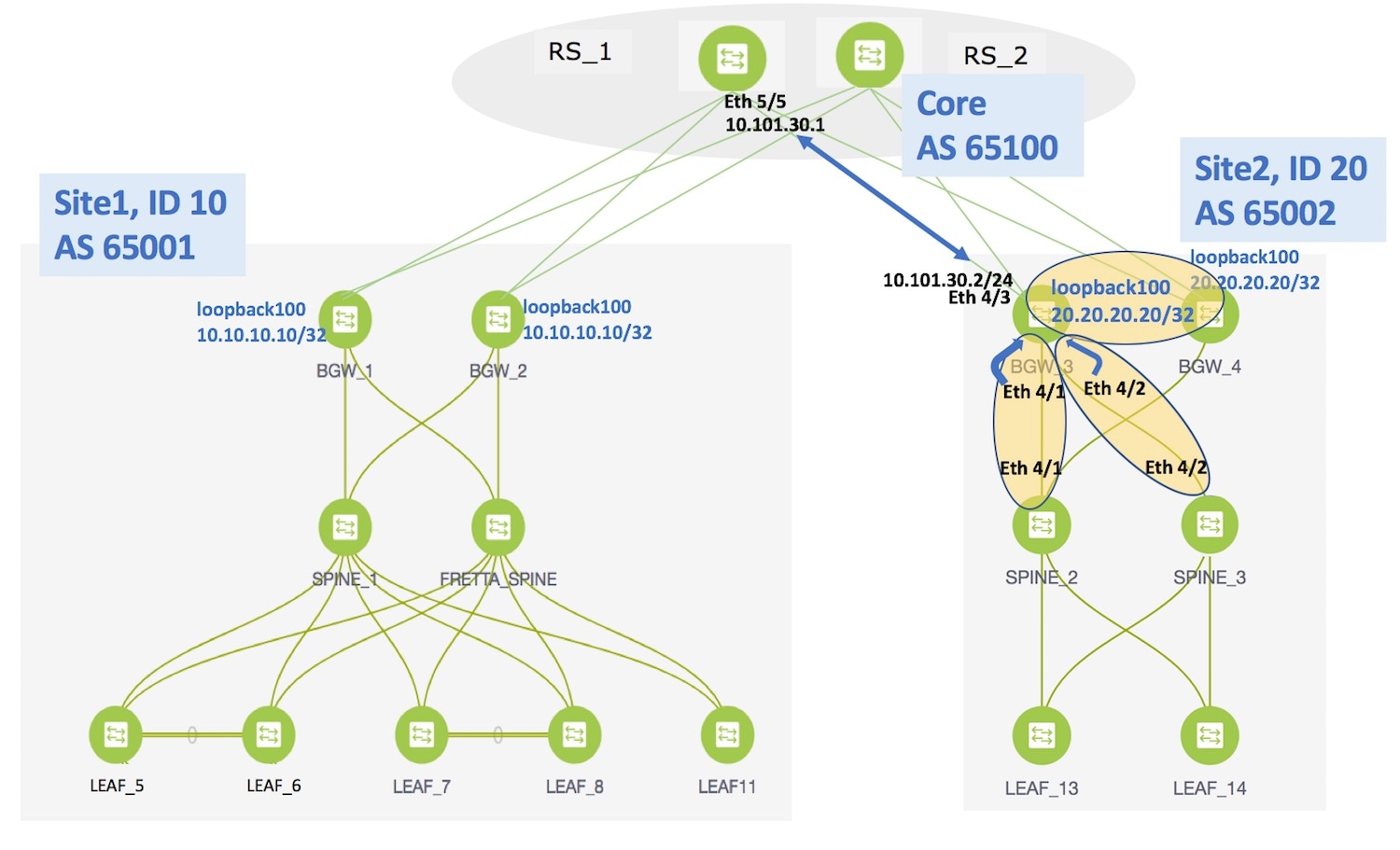
Fabric Interfaces—Fill up this field with the interfaces on BGW_3 that connects to other intra-fabric device ports. Since Ethernet 4/1 connects to SPINE_2 and Ethernet 4/2 connects to SPINE_3 in the topology, the interfaces should be entered over here.
Multisite Loopback ID and Multisite Loopback IP—These are the loopback ID and IP address of this EVPN Multi-Site instance.
Routing Protocol and Router ID—This is the IGP and the IGP instance ID within the fabric. Note that, if the IGP used in your setup is OSPF, the field has to be updated to OSPF.
OSPF AREA—OSPF area ID within the fabric.
A fully filled screen looks like this.
The corresponding topology depiction is given below:
Now that all the information is filled in, click Next to go to the Preview and Deploy section.
Here, you can preview the configuration that will be deployed to BGW_3. Note that no configuration will be pushed to the external device itself.
Click Save and Deploy to complete the task. This results in the configuration getting pushed to BGW_3. The external connection will appear in the Fabric Extension screen.
The view doesn't auto-refresh, hence the refresh button on the top right part of the screen needs to be clicked to trigger refresh. You can check the status of the deployment (Deployment Pending, Deployed, Failed) in the Status column. In this case, the status changes from Deployment Pending to Deployed after you click on the refresh button.
In case of FAILED or UNDEPLOYMENT FAILED status, use the hyperlink in the Status column to check the error messages for failure.
To view the configurations, click on View Config in the Configuration field.
After the underlay configuration, you need to configure the overlay configuration from BGW_3 to RS_1 (the external device connected to BGW_3), as shown in the next section.
Overlay Extension from BGW_3 to RS_1
Note | You can have multiple underlay connections to an external device but only one overlay connection from BGW_3 to each external device. |
In the Fabric Extension page, click on the + icon to add an external overlay connection. The Add Inter-Fabric Connection screen appears.
By default, VRF_LITE is populated in the Extension Type field. Change the selection to MULTISITE_OVERLAY. The screen changes accordingly.
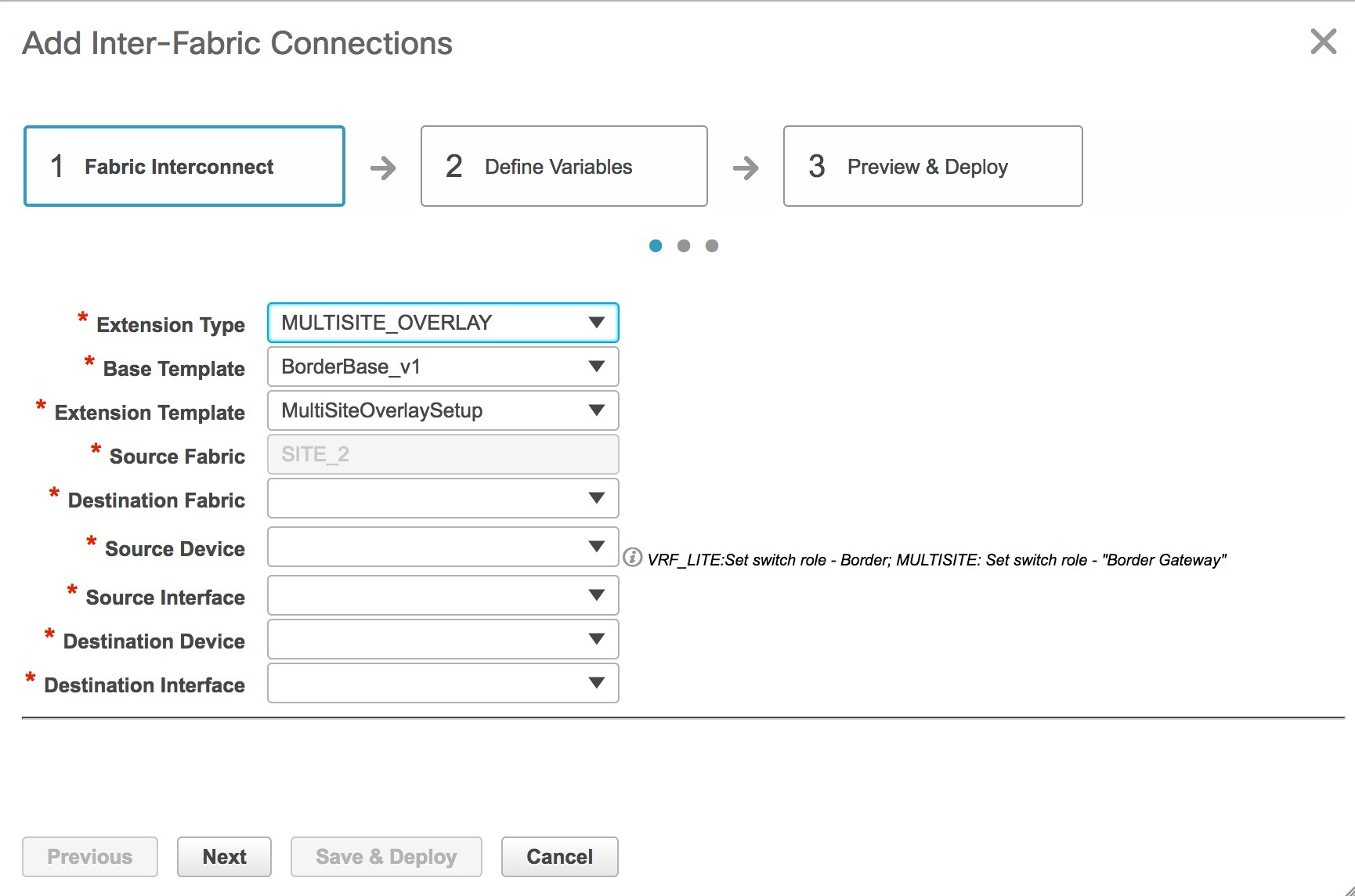
Base Template—BorderBase_v1 is auto-populated in this field. The BorderBase_v1 base template is a one-time configuration pushed to the BGW.
Extension Template—MultiSiteOverlaySetup is a setup template that contains the configuration that will be generated and pushed to the BGW to setup the corresponding inter-fabric connection. These templates are auto-populated with corresponding pre-packaged default templates based on your selection.
Source Fabric—This field is pre-populated with site2 since you are deploying the configurations in site2.
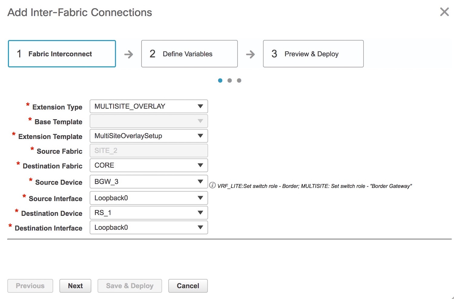
Destination Fabric—For the destination fabric, select the fabric that contains RS_1, CORE.
Source Device—Choose BGW_3 since the overlay connection is from BGW_3 to RS_1.
Source Interface—Typically, a loopback interface is created for the overlay. Choose the loopback interface amongst the 3 loopback interfaces you created as prerequisites. In this example, loopback0 is the BGP peer address.
Destination Device—Choose RS_1 since the overlay connection is from BGW_3 to RS_1.
Destination Interface—Choose the destination interface. Choose the interface which is the BGP peer address. Note that the destination interface is not used in generating the configuration.
After filling up the Fabric Interconnect section, the screen looks like this.
Click Next to go to the Define Variables section.
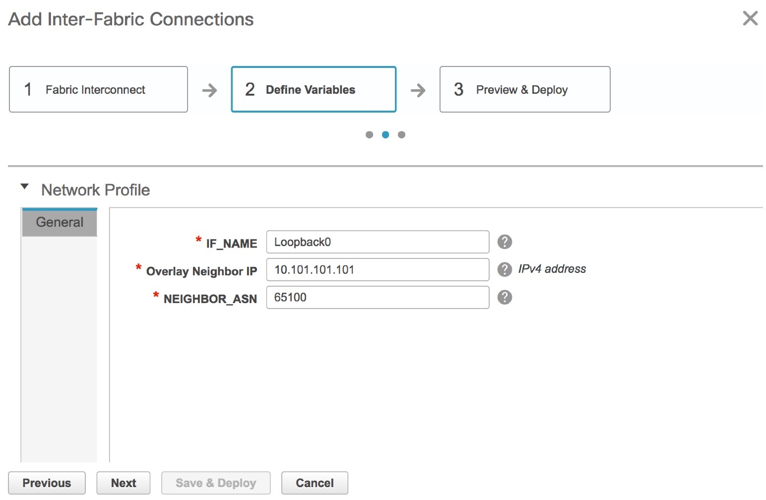
IF_NAME—In this field, the source interface is auto-populated from the previous step.
Overlay Neighbor IP—Enter the IP address on RS_1 that the overlay peers with. This is typically a loopback address.
NEIGHBOR_ASN—This field is populated with the RS_1's AS Number.
Click Next to go to the Preview and Deploy section.
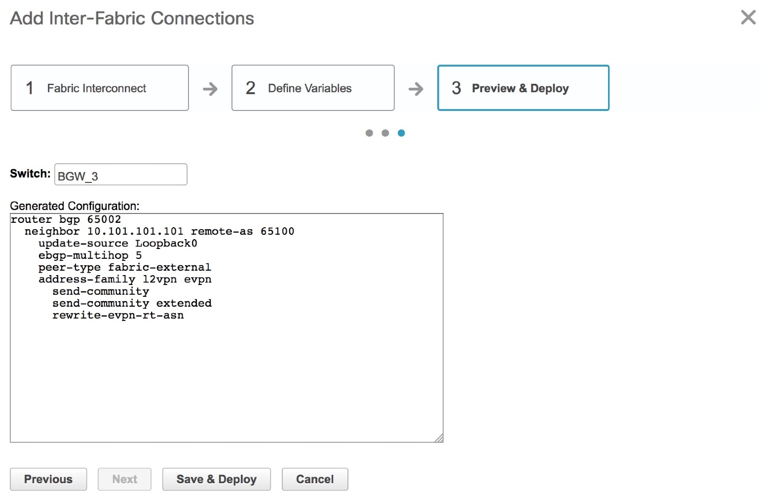
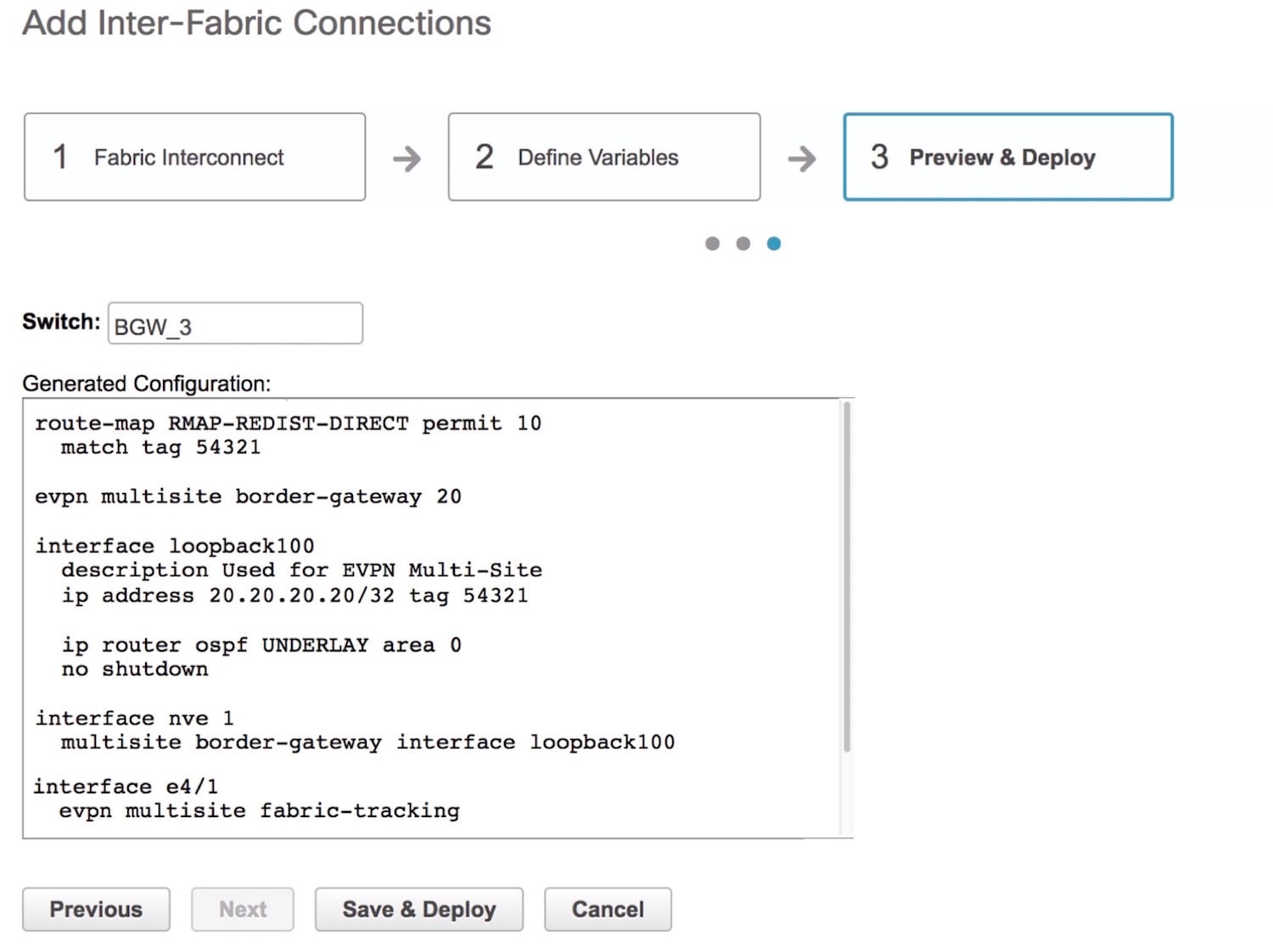
Here, you can preview the overlay configuration that will be deployed to BGW_3. In this section, you can see that an overlay connection is being established from Loopback0 on BGW_3 to the neighbor with AS Number 65100.
Note that no configuration will be pushed to the external device itself.
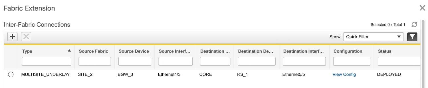
Click Save and Deploy to complete the task. This results in the configuration getting pushed to BGW_3. The external connection will appear in the Fabric Extension screen.
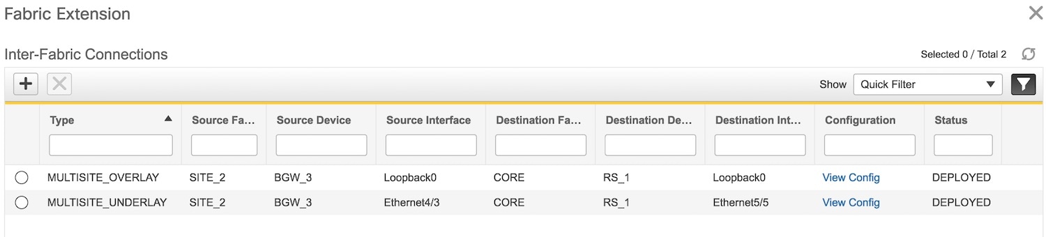
The view doesn't auto-refresh, hence the refresh button on the top right part of the screen needs to be clicked to trigger refresh. You can check the status of the deployment (Pending, Deployed, Failed) in the Status column. In case of FAILED or UNDEPLOYMENT FAILED status, use the hyperlink in the Status column to check the error messages for failure.
Note | Extensions will need to be deleted and then reconfigured in case of deployment failures. Currently there is no option to edit or redeploy an overlay or underlay extension. |
Other EVPN Multi-Site Configurations
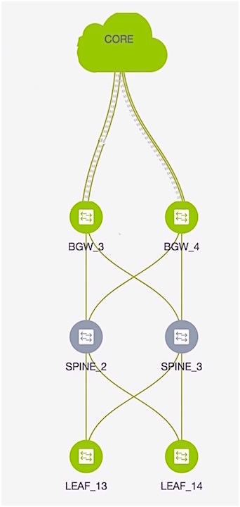
At this stage, overlay and underlay EVPN Multi-Site configurations are provisioned on BGW_3 towards RS_1 (as shown by the arrow in the figure).
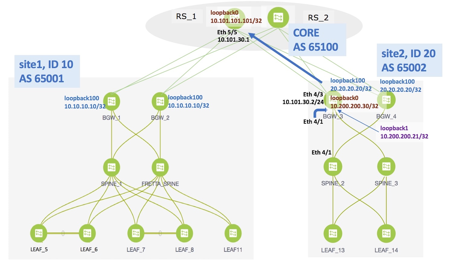
As noted earlier, the end-to-end Multi-Site configurations through DCNM Top-Down provisioning include these 2 steps:
(1) Multi-Site configurations on the BGWs (BGW_1, BGW_2, BGW_3 and BGW_4).
(2) Deploying Networks and VRF Instances on the leaf switches and the BGWs.
At this stage, the first step explanation is complete. In the next part of the document, the networks' configuration (second step), is explained. After appropriate network configurations on the leaf switches and BGWs, server traffic will flow across the 2 sites for the deployed and extended networks and VRFs.
Deploying Networks and VRF Instances
Typically, you create a fabric in DCNM, then create and deploy networks and VRFs on devices within the fabric on leaf switches, and then configure the BGWs for external connectivity. Though the focus of the document is external connectivity with EVPN Multi-Site configurations on BGWs using DCNM, for completeness and right context, network deployment on the BGWs is explained in this section. When EVPN Multi-Site deployment is completed, server traffic from these networks and VRFs on site2 will pass through a BGW (BGW_3 or BGW_4) towards site1.
Deploying Networks on the BGWs
Before you begin—In this scenario, we will deploy two networks in site2, MyNetwork_10000 and MyNetwork_10001, on the BGWs BGW_3 and BGW_4. You should ensure that you have already deployed the networks that you want to extend to site1 on the leaf switches ( LEAF_13 and LEAF_14 in this case).
After deploying the 2 networks on the leaf switches and the BGWs, the networks will be extended to site1. To know how to create a new fabric, network, and VRF, see LAN Fabric Provisioning section in the DCNM user guide.
In the Select a Fabric page, click the Continue button at the top right part of the screen.
(After Multi-Site overlays and underlays are created, the DCNM GUI automatically takes you to the Select a Fabric page).
After clicking Continue, the Networks page comes up.
We will deploy two new networks MyNetwork_10000 and MyNetwork_10001 on the BGWs. To do that, select the checkboxes (in the extreme left column).
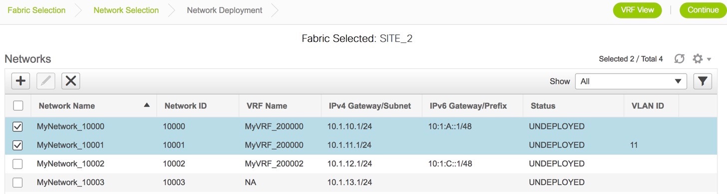
Note | In the image, you can see that the networks are deployed on the leaf switches (green color indicates deployed status). Note that the color code (and hence the deployment state) on switches is contextual and specific to the selection. In this scenario, the deployed state only depicts that networks MYNetwork10000 and MYNetwork10001 are deployed on leaf switches LEAF_13 and LEAF_14. It does not display information about other (networks and VRFs) deployment instances, if any. |
Select the multi-select check box at the bottom of the panel of options available at the right part of the page. (displayed as step 1 in the image).
Then, click your mouse (or track pad) and drag the cursor across BGW_3 and BGW_4. (step 2).
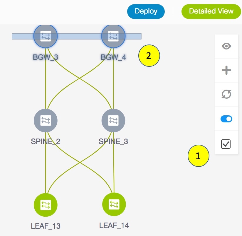
Immediately, the Switches Deploy screen (for networks) appears.
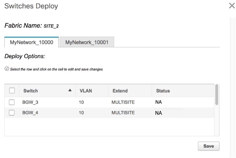
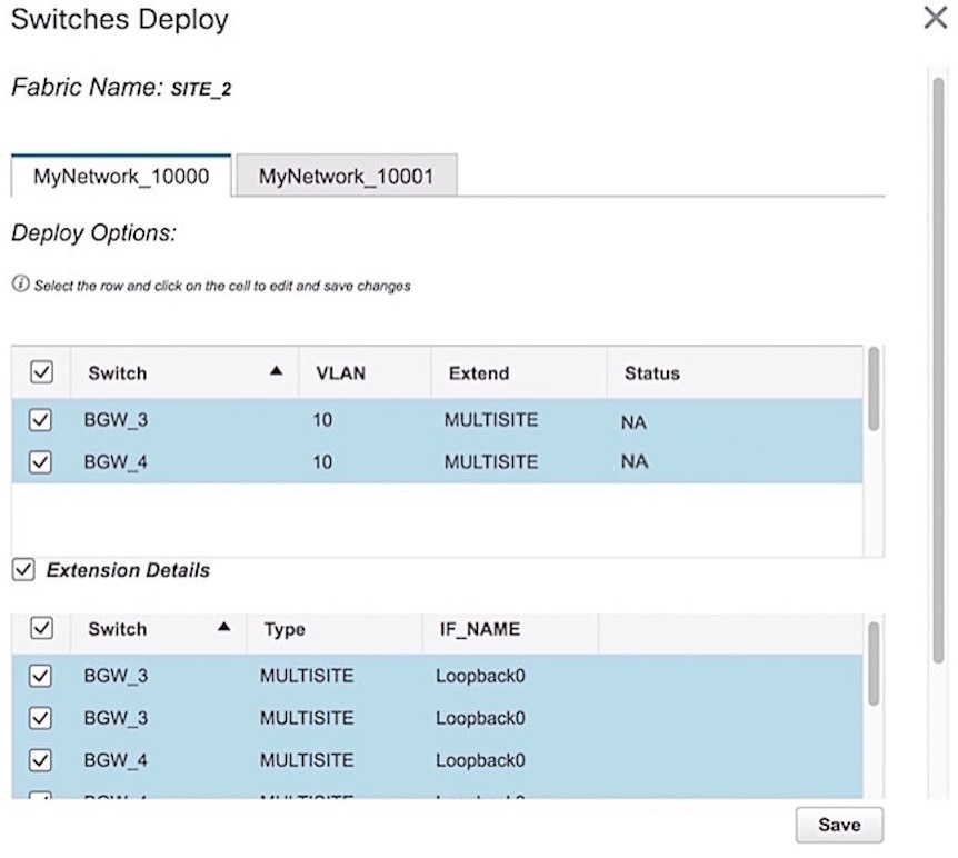
A tab is displayed for each network. Click the checkbox next to the Switch column. Both the BGW check boxes will be selected automatically and the Extension Details section will appear at the bottom part of the screen.
In the Extension Details section, select the Switch checkbox (or ensure that you select the check box in each row) and click Save (bottom right part of your screen).
After saving the details in this screen, the Network Deployment screen (Topology view) appears.
BGW_3 and BGW_4 will be displayed in blue color, indicating pending deployment. If you want to check your configurations again, click on the Preview (eye) icon.
After you verify that the configurations that are generated from the profiles are correct for the selected switches, click the Deploy button (on the top right part of the screen) to deploy the MYNetwork10000 and MYNetwork10001 network configurations on BGW_3 and BGW_4.
DCNM shows the deployment status in the topology by highlighting the switch icons with different colors, yellow for In Progress and green for Deployed.
From the snapshot, you can see that the 2 networks MYNetwork10000 and MYNetwork10001 have been implemented on the leaf switches and BGWs.
After configurations in site2 are complete, configure the following in site1 too.
Configurations in site1
Provision the networks MYNetwork10000 and MYNetwork10001 on the leaf switches (LEAF_5, LEAF_6, LEAF_7, LEAF_8, LEAF_11) and the BGWs (BGW_1 and BGW_2).
-
Since DCNM does not provision configurations for RS_1 and RS_2 (devices directly connected to the BGWs), enable appropriate configurations on these devices.
-
Configure the EVPN Multi-Site feature on the site1 BGWs (as explained in this document) so that server traffic from the 2 networks can flow to site2 and back.
Additional References
|
Document Title and Link |
Document Description |
|
This document explains Multi-Site design and deployment in detail. |
|
|
This document explains manual configurations for the Multi-Site solution. |
Appendix
Route Server Configurations
RS_1 configuration example for the overlay—The following configurations are enabled on RS1, and reproduced here for reference.
Note | switch(config)# refers to the global configuration mode. To access this mode, type the following on your switch: switch# configure terminal. |
switch(config)#

route-map ALL-PATHS permit 100
  set path-selection all advertise
route-map RMAP-REDIST-DIRECT permit 10
  match tag 12345
route-map UNCHANGED permit 10
  set ip next-hop unchanged

switch(config)#

interface loopback0
  ip address 10.101.101.101/32 tag 12345
line vty
router bgp 65100
  router-id 10.101.101.101
  address-family ipv4 unicast
    redistribute direct route-map RMAP-REDIST-DIRECT
    maximum-paths 4
    additional-paths send
    additional-paths receive
    additional-paths selection route-map ALL-PATHS
  address-family l2vpn evpn
    retain route-target all
  template peer OVERLAY-PEERING
    update-source loopback0
    ebgp-multihop 5
    address-family l2vpn evpn
      send-community both
      route-map UNCHANGED out
  neighbor 10.100.100.10
    inherit peer OVERLAY-PEERING
    remote-as 65001
    address-family l2vpn evpn
      rewrite-evpn-rt-asn
      route-map UNCHANGED out
  neighbor 10.100.100.20
    inherit peer OVERLAY-PEERING
    remote-as 65001
    address-family l2vpn evpn
      rewrite-evpn-rt-asn
      route-map UNCHANGED out
  neighbor 10.101.11.2
    remote-as 65101
    update-source Ethernet5/1
    address-family ipv4 unicast
      next-hop-self
  neighbor 10.101.12.2
    remote-as 65101
    update-source Ethernet5/2
    address-family ipv4 unicast
      next-hop-self
  neighbor 10.101.13.2
    remote-as 65102
    update-source Ethernet5/3
    address-family ipv4 unicast
      next-hop-self
  neighbor 10.101.14.2
    remote-as 65102
    update-source Ethernet5/4
    address-family ipv4 unicast
      next-hop-self
  neighbor 10.101.30.2
    remote-as 65002
    update-source Ethernet5/5
    address-family ipv4 unicast
      next-hop-self
  neighbor 10.101.40.2
    remote-as 65002
    update-source Ethernet5/6
    address-family ipv4 unicast
      next-hop-self
  neighbor 10.200.200.30
    remote-as 65002
    update-source loopback0
    ebgp-multihop 5
    address-family l2vpn evpn
      rewrite-evpn-rt-asn
      send-community both
      route-map UNCHANGED out
  neighbor 10.200.200.40
    remote-as 65002
    update-source loopback0
    ebgp-multihop 5
    address-family l2vpn evpn
      rewrite-evpn-rt-asn
      send-community both
      route-map UNCHANGED out
 Feedback