Cisco DCNM Web Client Online Help, 10.4(2) Release
Bias-Free Language
The documentation set for this product strives to use bias-free language. For the purposes of this documentation set, bias-free is defined as language that does not imply discrimination based on age, disability, gender, racial identity, ethnic identity, sexual orientation, socioeconomic status, and intersectionality. Exceptions may be present in the documentation due to language that is hardcoded in the user interfaces of the product software, language used based on RFP documentation, or language that is used by a referenced third-party product. Learn more about how Cisco is using Inclusive Language.
- Updated:
- June 20, 2016
Chapter: Configure
- Deploy
Configure
This section contains context-sensitive Online Help content for the Web Client > Configure tab.
- Deploy
- Templates
- Backup
- Image Management
- Credentials Management
- LAN Fabric Settings
- LAN Fabric Provisioning
- LAN Fabric Auto-Configuration
- Endpoint Locator
- SAN
Deploy
The Deploy menu includes the following submenus:
Configuring vPC Peer
A virtual PortChannel (vPC) allows links that are physically connected to two different Cisco Nexus devices to appear as a single PortChannel to a third device. The third device can be a Cisco Nexus 2000 Series Fabric Extender or a switch, server, or any other networking device. A vPC can provide Layer 2 multipathing, which allows you to create redundancy by increasing bandwidth, enabling multiple parallel paths between nodes and load-balancing traffic where alternative paths exist.
After you enable the vPC function, you create a peer keepalive link, which sends heartbeat messages between the two vPC peer devices.
The vPC domain includes both vPC peer devices, the vPC peer keepalive link, the vPC peer link, and all the PortChannels in the vPC domain connected to the downstream device. You can have only one vPC domain ID on each device.
vPC creation is divided into two steps, vPC Peer creation and vPC creation. In order to configure vPC user first needs to configure vPC domain. To create vPC Peer, navigate to Configure > Deploy > vPC Peer.
 Note | After you configure the vPC peer, select vPC peer using the radio button and click Add vPC. For information about how to add a vPC to the selected vPC peer, see Add vPC. |
You can view the history of tasks performed, navigate to Configure > Deploy > vPC Peer > History tab. For more information, see vPC Peer History.
You can view the list of vPC domains in the Pre Configured Peers table.
|
Column |
Description |
|---|---|
|
Search box |
Enter any string to filter the entries in their respective column. |
|
Domain ID |
Displays the domain ID of the vPC peer switches. |
|
Primary Switch |
Displays the vPC Primary device name. |
|
Primary Port Channel ID |
Displays the peer-link port channel for vPC primary device. |
|
Secondary Switch |
Displays the vPC secondary device name. |
|
Secondary Port Channel ID |
Displays the peer-link port channel for vPC secondary device. |
|
Consistency |
Displays the vPC Consistency status. Corresponds vPC peer-link configuration and Global Consistency parameters. |
This feature supports add, delete and edit option for Domain. You can also view vPC Peer History.
vPC Peer History
To view the deployed jobs on the vPC peers, navigate to Configure > Deploy > vPC Peer > History tab. You can view the list vPC Peer History information in the Table 1.
|
Column |
Description |
|---|---|
|
Domain Id |
Specifies the domain ID for the vPC peer |
|
Primary Switch |
Specifies the Primary Switch associated with the vPC Peer. |
|
Secondary Switch |
Specifies the Secondary Switch associated with the vPC Peer. |
|
Created By |
Specifies the DCNM username, who deployed this task. |
|
Started At |
Specifies the time at which the task was performed on the vPC peer. The time is displayed in the format YYYY-MM-DD HH:MM:SS. |
|
Task Performed |
Specifies the task performed on the vPC peer. |
|
Status |
Species the status of the task performed on the vPC Peer. The status can be Failed, Success, or in_progress. |
|
View Command History |
Select an activity, click View Command History. The Command History page displays the commands executed, status and error message on the Primary Switch and Secondary Switch, in their respective tabs. |
|
Delete vPC Peer Job |
Select a vPC Peer History entry and click Delete to delete the task history. |
Add vPC Peer Wizard
You can launch the vPC Peer configuration wizard by clicking the Add vPC Peer icon in the toolbar.
Delete vPC Peer
You can delete the vPC peer by clicking the Delete vPC Peer icon in the toolbar.
Edit vPC Peer Configuration
You can edit the vPC domain by clicking the Edit vPC Peer icon in the toolbar.
| Step 1 | From the menu bar, choose Configure > Deploy > vPC Peer tab. |
| Step 2 | Select the vPC
domain which you want to edit, and click the
Edit
vPC Peer icon in the toolbar.
You can edit the vPC Peer configuration by following the wizard as Add vPC Peer Wizard. |
Configuring vPC
After you finish configuring the vPC Peers, navigate to Configure > Deploy > vPC to configure the vPC.
You can view the history of tasks performed, navigate to Configure > Deploy > vPC > History. For more information, see vPC History.
You can view the list of virtual port-channels (vPC) in the Virtual Port-Channel(vPC) table.
|
Column |
Description |
|---|---|
|
Search box |
Enter any string to filter the entries in their respective column. |
| vPC ID |
Displays vPC ID's configured device. |
| Domain ID |
Displays the domain ID of the vPC peer switches. |
| Primary vPC Peer - Device Name |
Displays the vPC Primary device name. |
| Primary vPC Peer - Port Channel |
Displays the vPC port channel for primary vPC device connected to the multi-chassis endpoint or access switch. |
| Primary vPC Peer - Peer Port Channel |
Displays the peer-link port channel for vPC primary device. |
| Primary vPC Peer - Operational Mode |
Displays the operational mode of the primary vPC end points. |
| Secondary vPC Peer - Device Name |
Displays the vPC secondary device name. |
| Secondary vPC Peer - Port Channel |
Displays the vPC port channel for secondary device connected to the multi-chassis endpoint or access switch. |
| Secondary vPC Peer - Peer Port Channel |
Displays the peer-link port channel for vPC secondary device. |
| Secondary vPC Peer - Operational Mode |
Displays the operational mode of the secondary vPC end points. |
| Multi Chassis vPC EndPoints - Device Name |
Displays the multi-chassis vPC endpoints for each vPC ID under a vPC domain. |
| Multi Chassis vPC EndPoints - Port Channel ID |
Displays the port channel on multi chassis vPC devices or access devices connected to the vPC peer switches. |
| vPC Consistency |
Displays the vPC Consistency status. Corresponds vPC port channel and vPC. |
This feature supports add, delete and edit option for vPC.
vPC History
To view the deployed jobs on the created vPC peers, navigate to Configure > Deploy > vPC > History tab. You can view the list vPC Peer History information in the table.
|
Column |
Description |
|---|---|
|
vPC Id |
Specifies the domain ID for the vPC peer. |
|
Primary Switch |
Specifies the Primary Switch associated with the vPC. |
|
Secondary Switch |
Specifies the Secondary Switch associated with the vPC. |
|
Access Switch |
Specifies the Access Switch associated with the vPC. |
|
Created By |
Specifies the DCNM username who deployed this task. |
|
Started At |
Specifies the time at which the task was performed on the vPC peer. The time is displayed in the format YYYY-MM-DD HH:MM:SS. |
|
Task Performed |
Specifies the task performed on the vPC. |
|
Status |
Species the status of the task performed on the vPC. |
|
View Command History |
Select an activity, click View Command History. The Command History page displays the commands executed, status and error message for every command on the Primary Switch, Secondary Switch, and Access Switch, in their respective tabs. |
|
Delete vPC Job |
Select a vPC history and click Delete to delete the task history. |
Add vPC
You can launch the vPC configuration wizard by clicking the Add vPC icon in the toolbar.
| Step 1 | From the menu bar, choose Configure > Deploy > vPC tab. | ||
| Step 2 | Click the
Add
vPC icon in the toolbar.
You are directed to the vPC creation wizard. There are five steps to complete the vPC creation.
| ||
| Step 3 | In the Select Devices page, click on search button next to the Primary Switch text box to open a list of vPC peers.
After selection, click OK. Once the domain is selected the vPC domain page gets pre-populated with vPC domain information.
Click Ok. | ||
| Step 4 | In the
vPC
ID field, enter the value for this vPC.
By default, this field is auto-populated when selecting Devices. Select the option to Configure Access Switch/Fex, Configure New Fex or Configure Host and specify the Access Switch/Fex. A dual-home FEX will be created after you successfully deploy the vPC. | ||
| Step 5 | To enable
LACP on VPC port-channels, check
Create LACP Based Port Channels For Setting Up vPC
checkbox.
| ||
| Step 6 | In the Configure links with vPC Primary and vPC Secondary page, configure the port channel for the Primary and Secondary vPC. | ||
| Step 7 | Select or
create the port-channel to configure the vPC. Click
Existing Port Channel or
Create New port Channel radio button to configure
port channel.
A port channel bundles physical links into a channel group to create a single logical link that provides the aggregate bandwidth of up to 8 physical links on the M series module. If a member port within a port channel fails, the traffic previously carried over the failed link switches to the remaining member ports within the port channel.
Click Next to review and modify other vPC port channel settings. | ||
| Step 8 | In the
Configure vPC Port Channel Settings, review and configure parameters for the
port channel for both Primary and Secondary switches.
Edit the Description, Port Mode, Native VLAN and Protocol for the port channels of the primary and the secondary devices. If you did not check the Create LACP based Port Channels for setting up vPC in the Select Devices screen, the Protocol field will display NONE. If you want to create VLANs, the Allowed VLANs value must be a valid VLAN ID or range. Click Next. | ||
| Step 9 | In
theSummary page, you can view the summary of your
configuration for the Primary Switch, Secondary Switch, and Access Switch.
You can copy and save the configuration this configuration to your local directory. | ||
| Step 10 | Click Previous to change any configurations. | ||
| Step 11 | Click
Deploy to configure vPC on the devices.
After the deployment is complete, a status message shows whether the deployment is successful or a failure. Click Know More to view the status of each command deployed. |
Delete vPC
You can delete the virtual Port-Channel by clicking the Delete vPC icon in the toolbar.
Edit vPC Configuration
You can edit the vPC configuration by clicking the Edit vPC icon in the toolbar.
| Step 1 | From the menu bar, choose Configure > Deploy > vPC tab. |
| Step 2 | Select the vPC
which you want to edit, and click the
Edit
vPC icon in the toolbar.
You can edit the selected vPC configuration by following the Add vPC. |
POAP Launchpad
Note | These features appear on your Cisco DCNM Web Client application only if you have deployed the Cisco DCNM installer in the Unified Fabric mode. |
The POAP launchpad contains the following configuration steps:
Power-On Auto Provisioning (POAP)
Power-On Auto Provisioning (POAP) automates the process of upgrading software images and installing configuration files on Cisco Nexus switches that are being deployed in the network for the first time.
When a Cisco Nexus switch with the POAP feature boots and does not find the startup configuration, the switch enters POAP mode, locates a DHCP server and bootstraps itself with its interface IP address, gateway, and DNS server IP addresses. It also obtains the URL of an SCP server and downloads a configuration script that is run on the switch to download and install the appropriate software image and configuration file.
Note | When you move the mouse cursor over an error identified in a specific parameter in any window, it will display the exact error message before you move to the next screen. |
DHCP Scopes
DHCP scope is a well-defined term in DHCP arena. It is used to define a policy for giving out IP addresses and other options to host on a specific IP subnet. In DCNM, we use the DCHP scope to distribute IPv4 address, PYTHON bootscript, (or other supported protocol + access credential + server) which stores the bootscript.
From the menu bar, select Configure > Deploy > POAP.
The following table details the columns in the display.
|
DHCP Scopes |
Comment |
|---|---|
|
Scope Name |
The DHCP scope name must be unique amongst the switch scopes. This name is not used by ISC DHCP but used to identify the scope. |
|
Scope Subnet |
The IPv4 subnet used by the DHCP servers. |
|
IP Address Range |
The IP address ranges allocated to the POAP switches. Multiple IP addresses can be used, separated by comma. |
|
Lease Time |
Maximum lease time for the DHCP lease. |
|
Default Gateway |
The default gateway for the DHCP scope. You must enter a valid IP as the default gateway. |
|
Domain Name Servers |
The domain name server for the DHCP scope. |
|
Bootscript Name |
The Python Bootup script. |
|
TFTP/Bootscript Server |
The server that holds the bootscript. |
Adding a DHCP Scope
| Step 1 | From the menu bar, select Configure > Deploy > POAP > DHCP Scopes. |
| Step 2 | Click Add scope icon. |
| Step 3 | In the Add DHCP Scope window, specify values in the fields according to the information in Table 1. |
| Step 4 | Click OK to add a DHCP scope. |
Editing an existing DHCP Scope
Note | Once the DCNM is accessed for the first time, you must edit the default scope named enhanced_fab_mgmt and add free IP address ranges. |
Deleting a DHCP Scope
Image and Configuration Servers
The Image and Configuration Servers page allows you to specify the servers and credentials used to access the device images and the uploaded or Cisco DCNM generated or published device configuration. The server that is serving the images could be different from the one serving the configurations. If the same server is serving both images and configurations, you need to specify the server IP address and credentials twice for each server because the root directory holding the images or configuration files could be different. By default, the Cisco DCNM server will be the default image and configuration server. There will be two Cisco DCNM server addresses, one for configuration, one for image.
From the menu bar, choose Configure > Deploy > POAP. The Power-On Auto Provisioning (POAP) page appears. Click Images and Configuration.
The following table details the columns in the display.
|
Image and Configuration Servers |
Description |
|---|---|
|
Name |
Name of the image and configuration server. |
|
URL |
URL shows where images and files are stored. |
|
Username |
Indicates the username. |
|
Last Modified |
Indicates the last modified date. |
You can add your own image and configuration servers if they are different from the default.
- Add Image or Configuration Server URL
- Editing an Image or Configuration Server URL
- Deleting an Image or Configuration Server URL
Add Image or Configuration Server URL
Perform the following task to add an image or a configuration server URL:
| Step 1 | On the Image and Configuration Servers page, click the Add icon. |
| Step 2 | In the Add Image or Configuration Servers URL window, specify a name for the image. |
| Step 3 | Click the scp radio button to select the SCP protocol for POAP and Image Management. |
| Step 4 | Enter Hostname/Ipaddress and Path. |
| Step 5 | Specify the Username and Password. |
| Step 6 | Click OK to save. |
Editing an Image or Configuration Server URL
Perform the following task to edit an image or a configuration server URL to the repository.
| Step 1 | On the Image and Configuration Servers page, select an existing Image and Configuration Server from the list, and click the Edit icon. |
| Step 2 | In the Edit Image or Configuration Servers URL window, edit the required fields.
The Default_SCP_Repository cannot be edited. |
| Step 3 | Click OK to save or click Cancel to discard the changes. |
Deleting an Image or Configuration Server URL
Perform the following task to delete an image or a configuration server URL to the repository.
POAP Templates
Templates can be created or imported into the template builder of DCNM. There are some predefined Fabric specific POAP templates bundled with DCNM. The template builder can be invoked from the GUI, Configure > Templates > Deploy. The templates dedicated to POAP will be used to generate many different POAP device configurations
The following icons are listed at the menu bar of the window to customize the view of the information in the window:
-
Use the Show Filter icon to filter the templates.
-
Use the Print icon to print the list of templates and their details.
-
Use the Export icon to export the list of templates to a Microsoft Excel spreadsheet.
This section contains the following:
- Add POAP template
- Editing a Template
- Cloning a Template
- Importing a Template
- Exporting a Template
- Deleting a Template
Add POAP template
| Step 1 | From the menu bar, select Configure > Deploy > POAP > POAP Definitions. |
| Step 2 | In the Configuration Steps, click the template hyperlink in the POAP Definitions section. |
| Step 3 | Click Add template icon. |
| Step 4 | Specify the Template Name, Template Description and Tags. |
| Step 5 | Use the checkbox to specify the Supported Platforms. |
| Step 6 | Select the template type from the drop-down list.
By default, CLI template type is selected. |
| Step 7 | Select the Published checkbox if you want the template to have ‘Read Only’ access. |
| Step 8 | In the Template Content pane, you can specify the content of the template.
For help on creating the template content, click the Help icon next to the Template Content header. For information about POAP template annotations see the POAP Template Annotation section. |
| Step 9 | Click Validate Template Syntax to validate syntax errors. |
| Step 10 | Click Save to save the template. |
| Step 11 | Click Save and Exit to save the template and exit the window. |
| Step 12 | Click Cancel to discard the template. |
Editing a Template
| Step 1 | From the menu bar, select Configure > Deploy > POAP > POAP Definitions. |
| Step 2 | In the Configuration Steps, click the template hyperlink in the POAP Definitions section. |
| Step 3 | Select a template from the list and click Modify/View template icon. |
| Step 4 | Edit the template content and click Save to save the template or Save and Exit to save and exit the screen. |
Cloning a Template
| Step 1 | From the menu bar, select Configure > Deploy > POAP > POAP Definitions. |
| Step 2 | In the Configuration Steps, click the template hyperlink in the POAP Definitions section. |
| Step 3 | Select a template from the list and click Save Template As icon. |
| Step 4 | Edit the template and click Save to save the template or Save and Exit to save and exit the screen. |
Importing a Template
Exporting a Template
Deleting a Template
Note | Only user-defined templates can be deleted. |
POAP Template Annotation
Annotation is used to add semantic, validation logic and description to the template variable.
The Annotation for a given template variable is required to precede the given template variable. Only one annotation statement is required for each template variable. When a template variable has an associated annotation statement, the template variable has to be declared on a single line, Multiple variables cannot be declared under the same annotation statement.
Format of an annotation statement is as follows:
@(<key1>=<value1>,<key2>=<value2>, ..., <keyN>=<valueN>)
Note | Each annotation statement is composed of one or more key-values pair. |
The following is a sample template variable, “hostname”, with annotation statement with the keys “DisplayName”, and “Description”:
@(DisplayName=”Host Name”, Description = “Description of the host”)
String hostname;
The table displays the supported keys in the annotation statement:
|
Key Name |
Default Value |
Description |
|---|---|---|
|
DisplayName |
Empty String |
The value is displayed as a variable label in the template form GUI, on POAP definition screen. |
|
Description |
Empty String |
Displays the description next or below the template variable field in the template form GUI. |
|
IsManagement |
false |
The associated variable is of IP Address type. This will be used as the management IP address. DCNM used this IP address to manage the devices. |
|
IsMultiplicity |
false |
If true, this single value can take multiple values. For example; when it is used with IsManagement annotation, it allows you to type in multiple IP addresses and assign each IP address to a device. |
|
IsSwitchName |
false |
The associated variable value is used as the device host name. |
|
IsMandatory |
true |
It marks the field as mandatory if the value is set as ‘true’. |
|
UseDNSReverseLookup |
false |
This annotation compliments the IsSwitchName annotation. Once they are associated with a variable. The variable is populated with the reverse DNS name, if available during the creation time of the corresponding POAP definition record. |
|
IsFabricPort |
false |
The associated variable value contains a list of the ports used as fabric ports. The variable value will be used by the cable plan generation from POAP |
|
IsHostPort |
false |
Trunk ports connected to host/servers. |
|
IsVPCDomainID |
false |
Used as the vPC Domain ID. |
|
IsVPCPeerLinkSrc |
false |
Used as the VPC IPv4 source address. |
|
IsVPCPeerLinkDst |
false |
Used as the VPC IPv4 peer address. |
|
IsVPCPeerLinkPortChannel |
false |
Used for VPC port channel. |
|
IsVPCLinkPort |
false |
Used for VPC interface. |
|
IsVPC |
false |
Used as a VPC record. |
|
IsVPCID |
false |
Individual VPC ID. |
|
IsVPCPortChannel |
false |
Individual VPC port channel. |
|
IsVPCPort |
false |
VPC Interface. |
POAP Definitions
The POAP switch definition has two major functions:
You must copy the Cisco DCNM license files to the /var/lib/dcnm/license directory to install as part of the POAP process.
You must also copy the device licenses to the /var/lib/dcnm/licenses folder.
Note | The device licenses refers to the devices monitored by the Cisco DCNM. |
The following fields and icons are listed at the menu bar of the window to customize the view of the information in the window:
|
Fields and Icons |
Description |
|---|---|
|
Serial Number |
Specifies the serial number for the switch. |
|
Switch ID |
Specifies the ID defined for the switch |
|
Management IP |
Specifies the Management IP for the switch. |
|
Status |
|
|
Switch Status |
Indicates if the switch is published or not. |
|
Publish Status |
Indicates if this POAP template has been published successfully to the TFTP site. |
|
Bootscript Status |
Indicates the Bootscript execution state when the device executed POAP. For details, view the “Boot Log” file. |
|
Diff State |
Specifies if the configuration defined in POAP is different from the running configuration on the device. If a difference is detected, the user has an option to make changes to the device configuration, thereby ensuring that the configuration on the device in sync with the POAP configuration. The different states are:
|
|
Model |
Specifies the model of the switch. |
|
Template/Config File Name |
Specifies the template used for creating the POAP definition. Fabric and IPFabric POAP templates are available. |
|
Bootscript Last Updated Time |
Specifies the last updated time for bootscript. |
|
Last Published |
Specifies the last published time for the POAP definition. |
|
POAP Creation Time |
Specifies the time when the POAP definition was created. |
|
System Image |
Specifies the System Image used while creating the POAP definition. |
|
Kickstart Image |
Specifies the kickstart image used the POAP definition. |
|
Icons |
|
|
Add |
Allows you to add a POAP definition. For more information, see Creating a POAP definition. |
|
Edit |
Allows you to edit a POAP definition. For more information, see Editing a POAP Definition. |
|
Delete |
Allows you to delete a POAP definition. For more information, see Deleting POAP Definitions. |
|
Write Erase and Reload |
Allows you to reboot and reload a POAP definition. For more information, see . |
|
Change Image |
Allows you to change the image for the defined POAP definition. For more information, see Change Image. |
|
Boot Log |
Display the list and view log files from the device bootflash. |
|
Update Serial Number |
Allows the user to modify the serial number of the POAP definition. |
|
Refresh Switch |
Refreshes the list of switches. |
|
Refresh Diff State |
Refreshes the Diff state. |
|
Show Filter |
Filters list of switches based on the defined value for each column. |
|
|
Prints the list of devices and their details. |
|
Export |
Exports the list of devices and their details to a Microsoft Excel spreadsheet. |
|
Select Columns |
Displays the columns to be displayed. You can choose to show/hide a column. |
Note | Each annotation statement is composed of one or more key-values pair. The value can be true, false or a string. If the value is a string, it should be mentioned in double-quotes. |
This section contains the following:
- Creating a POAP definition
- Uploading a POAP Definition
- Editing a POAP Definition
- Deleting POAP Definitions
- Publishing POAP definitions
- Write, Erase and Reload the POAP Switch Definition
- Change Image
- Updating the Serial Number of a Switch for an existing POAP Definition
Creating a POAP definition
| Step 1 | From the menu bar, select Configure > Deploy > POAP > POAP Definitions. | ||
| Step 2 | From the Scope drop-down list, select the scope for POAP definition. | ||
| Step 3 | Click Add to add a new POAP definition. | ||
| Step 4 | Click on Generate Definition radio button to generate POAP definition from a template, and click Next to specify the switch details. | ||
| Step 5 | Enter the
serial number of switches separated by comma. Alternatively, you can click
Import
from CSV File to import the list of switches.
| ||
| Step 6 | Use the drop-down list to select the Switch Type. | ||
| Step 7 | Use the drop-down list to select the Image Server. | ||
| Step 8 | Use the drop-down list to select the System Image and Kickstart image. | ||
| Step 9 | Specify the Switch User Name and Switch Password. | ||
| Step 10 | Click Next to Select the Switch Config Template. | ||
| Step 11 | Use the drop-down to select the Template and click View to specify the Template Parameters. | ||
| Step 12 | Enter Template Parameters. | ||
| Step 13 | From the Settings File drop-down list to select the file. If the settings file in unavailable, click Save Parameter as New Settings File button to specify a name for the settings file. | ||
| Step 14 | Select the variables and click Manage. | ||
| Step 15 | Click Add to see the variables to be saved. Specify a name for the settings file and click Save. | ||
| Step 16 | Click Manage to modify the settings file parameters. | ||
| Step 17 | Click Preview CLI to view the generated configuration. | ||
| Step 18 | Click Finish to publish the POAP definition. | ||
| Step 19 | Click Next to generate the configuration. |
Uploading a POAP Definition
| Step 1 | From the menu bar, select Configure > Deploy > POAP > POAP Definitions. |
| Step 2 | Click Upload Startup Config radio button to upload startup configuration to the POAP repository Server, and click Next to enter the switch details. |
| Step 3 | Enter the serial number of switches separated by comma. |
| Step 4 | Use the drop-down to select the Switch Type. |
| Step 5 | Use the drop-down to select the Image Server. |
| Step 6 | Use the drop-down to select the System Image and Kickstart Image. |
| Step 7 | Specify the Switch User Name and Password. |
| Step 8 | Click Browse to select the upload configuration file. |
| Step 9 | Click Finish to publish the POAP definition. |
Editing a POAP Definition
| Step 1 | From the menu bar, select Configure > Deploy > POAP > POAP Definitions. | ||
| Step 2 | Select the POAP switch definitions from the list and click the Edit icon. | ||
| Step 3 | Follow the steps listed in
Creating a POAP definition
and
Uploading a POAP Definition
sections.
|
Deleting POAP Definitions
| Step 1 | From the menu bar, select Configure > Deploy > POAP > POAP Definitions. |
| Step 2 | Select the POAP switch definitions from the list and click the Delete icon. |
| Step 3 | Click
Yes to delete the switch definitions.
A prompt appears to delete the device from the data source. Check or uncheck the checkbox based if you want to delete the switches associated with the POAP Definition. |
| Step 4 | Click OK to confirm to delete the device. Based on the check box, the device will be deleted from the data source also. |
Publishing POAP definitions
Write, Erase and Reload the POAP Switch Definition
| Step 1 | From the menu bar, select Configure > Deploy > POAP > POAP Definitions. |
| Step 2 | Select the POAP switch definitions from the list and click the Edit icon. |
| Step 3 | Click the Write Erase and Reload button.
The Write Erase and Reload button works only when the selected switch(es) are listed in the Inventory > Discovery > LAN Switches screen. Also, valid credentials must be specified in the Configure > Credentials Management > LAN Credentials screen. |
| Step 4 | Click Continue to reboot and reload the switch definitions. |
Change Image
| Step 1 | From the menu bar, select Configure > Deploy > POAP > POAP Definitions. | ||
| Step 2 | Select the POAP switch definitions from the list and click the Edit icon. | ||
| Step 3 | Select the
switch for which you need to change the image. Click
Change
Image.
The Multi Device Image Change screen appears. | ||
| Step 4 | From the Image Server drop down list, select the server where the new image is stored. | ||
| Step 5 | From the System Image drop down list, select the new system image. | ||
| Step 6 | From the Kickstart Image drop down list, select the new image which will replace the old image. | ||
| Step 7 | Click OK to apply and change the image. |
Updating the Serial Number of a Switch for an existing POAP Definition
| Step 1 | Ensure that the old switch is in place with POAP definition and discovered. |
| Step 2 | Manually update serial number in Cisco DCNM on the POAP screen. Note: this button may be hidden underneath a >> button. Now two devices in Cisco DCNM will have the same IP address. |
| Step 3 | Physically remove the old switch from the network. |
| Step 4 | Place the new switch in the rack and connect network cables and power. Bring up the new switch. The new switch reboots several times so that it comes up with necessary configurations. |
| Step 5 | Manually rediscover the switches in Cisco DCNM. Now there will be one device in Cisco DCNM with the same IP. |
Cable Plan
Note | If you are generating POAP definitions from the uploaded configuration, then generation of cable plan using the option of “Generate Cable Plan from POAP definition” will not work as the POAP definitions generated from the uploaded configuration will not have the required meta-data to generate the cable plans. You must select either “Capture from Existing Deployment” or “Import Cable plan file” to create a cable plan. |
The Cable plan configuration screen has the following options:
- Create a Cable Plan
- Viewing an Existing Cable Plan Deployment
- Deleting a Cable Plan
- Deploying a Cable Plan
- Revoking a Cable Plan
- Viewing a Deployed Cable Plan from Device
Create a Cable Plan
| Step 1 | From the menu bar, select Configure > Deploy > POAP > Cable Plan. |
| Step 2 | Click
Create Cable Plan.
In the Create Cable Plan pop-up, use the radio button to select the options. |
| Step 3 | If you select:
|
Viewing an Existing Cable Plan Deployment
| Step 1 | From the menu bar, select Configure > Deploy > POAP > Cable Plan. |
| Step 2 | Click View. |
| Step 3 | In the Cable Plan – Existing_Deployment window, you can view the existing cable plan deployments. |
| Step 4 | You can use the Table View and XML View icons to change the view of the cable plan deployments table. |
Deleting a Cable Plan
Deploying a Cable Plan
Revoking a Cable Plan
Viewing a Deployed Cable Plan from Device
Templates
The Templates menu includes the following submenus:
Deploying Templates
Cisco DCNM allows you to add, edit or delete user-defined templates configured across different Cisco Nexus and Cisco MDS platforms. The following parameters are displayed for each template configured on the Web Client of the Cisco DCNM Configure > Templates > Deploy. This uses the Java runtime provided Java script environment to perform arithmetic operations, string manipulations in the template syntax.
The following table describes the fields that appear on this page.
|
Field |
Description |
|---|---|
|
Add Template |
Allows you to add a new template. |
|
Launch job creation wizard |
Allows you to create jobs. |
|
Modify/View Template |
Allows you to view the template definition and modify as required. |
|
Save Template As |
Allows you to save the selected template in a different name. You can edit the template as required. |
|
Delete Template |
Allows you to Delete a template |
|
Import Template |
Allows you to import a template from your local directory, one at a time. |
|
Export template |
Allows you tot export the template configuration to a local directory location. |
|
Import Template Zip File |
Allows you to import .zip file, that contains more than one template bundled in a .zip format All the templates in the zip file will be extracted and listed in the table as individual templates. |
|
Field |
Description |
|---|---|
|
Name |
Displays the name of the configured template. |
|
Description |
Displays the description provided while configuring templates. |
|
Platforms |
Displays the supported Cisco Nexus platforms compatible with the template. |
|
Tags |
Displays the tag assigned for the template and aids to filter templates based on the tags. |
|
Template Type |
Displays the type of the template. |
|
Template Sub Type |
Specifies the sub type associated with the template. |
|
Published |
Specifies if the template is published or not. |
|
Modified Time |
Displays the date and time when the template was last modified, in the format YYYY-MM-DD HH:MM:SS. |
Additionally, from the menu bar, select Configure > Delivery > Templates and you can also:
-
Click the Launch Job Creation icon to configure and schedule jobs for individual templates. For more information, see Configuring Template Job.
-
Click the Show Filter icon to filter the templates based on the headers.
-
Click the Print icon to print the list of templates.
-
Click the Export to Excel icon to export the list of template to a Microsoft Excel spreadsheet.
This section contains the following:
- Template Structure
- Adding a Template
- Configuring Template Job
- Modifying a Template
- Importing a Template
- Installing POAP Templates
- Exporting a Template
- Deleting a Template
Template Structure
The configuration template content mainly consists of four parts. You can click on the Help icon next to the Template Content window for information about editing the content of the template. Click on the Help icon next to the Template Content window for information about editing the content of the template.
This section contains the following:
- Template Format
- Template Variables
- Variable Meta Property
- Variable Annotation
- Templates Content
- Advanced Features
Template Format
This section describes the basic information of the template. The possible fields are as detailed in the table below.
|
Property Name |
Description |
Valid Values |
Optional? |
|---|---|---|---|
|
name |
The name of the template |
Text |
No |
|
description |
Brief description about the template |
Text |
Yes |
|
userDefined |
Indicates whether the user created the template. Value is ‘true’ if user created. |
“true” or “false” |
Yes |
|
supportedPlatforms |
List of device platforms supports this configuration template. Specify ‘All’ to support all platforms. |
N1K, N3K, N3500, N4K, N5K, N5500, N5600, N6K, N7K, N9K, MDS, VDC list separated by comma. |
No |
|
configType |
Specifies the type of Template used. |
Yes |
|
|
Template Sub Type |
Specifies the sub type associated with the template. |
|
|
|
published |
Used to Mark the template as read only and avoids changes to it. |
“true” or “false” |
Yes |
|
timestamp |
Shows the template modified time |
Modified date and time in the format YYYY-MM-DD HH:MM:SS |
Yes |
Example: Template Properties
##template properties
name =FCOE template;
description = This file specifies the template configuration for FCOE;
userDefined= false;
supportedPlatforms = N7K, N6K, N5K, N5500, MDS;
templateType = CLI;
templateSubType=NA;
published = false;
timestamp = 2013-05-16 07:11:37;
##
Template Variables
This section contains declared variables, the data type, default values, and valid values conditions for the parameters that are used in the template. These declared variables are used for value substitution in the template content section during the dynamic command generation process. Also these variables are used in decision making and in iteration blocks in the template content section. Variables have predefined data types. You can also add a description about the variable. The following table describes the syntax and usage for the available datatypes.
|
Variable Type |
Valid Value |
Iterative? |
|---|---|---|
|
string |
Free text Example: Description for the variable |
No |
|
boolean |
true|false |
No |
|
enum |
Example: running-config, startup-config |
No |
|
float |
Floating number format |
No |
|
Integer |
Any number |
No |
|
ipAddress |
IPv4 OR IPv6 address |
No |
|
ipV4Address |
IPv4 address |
No |
|
ipV6Address |
IPv6 address |
No |
|
ipV4AddressWithSubnet |
Example: 192.168.1.1/24 |
No |
|
ipV4AddressWithSubnet |
Example: 1:2:3:4:5:6:7:8/22 |
No |
|
ipV6AddressWithPrefix |
Example: 1:2:3:4:5:6:7:8 22 |
No |
|
ipAddressWithoutPrefix |
Example: 192.168.1.1 or Example: 1:2:3:4:5:6:7:8 |
No |
|
macAddress |
14 or 17 character length MAC address format |
No |
|
interface |
Format: <if type><slot>[/<sub slot>]/<port> Example: eth1/1, fa10/1/2 etc. |
No |
|
integerRange |
Contiguous numbers separated by “-“ Discrete numbers separated by “,” Example: 1-10,15,18,20 |
Yes |
|
floatRange |
Example: 10.1,50.01 |
Yes |
|
ipV4AddressRange |
Example: 172.22.31.97 - 172.22.31.99, 172.22.31.105 - 172.22.31.109 |
Yes |
|
interfaceRange |
Example: eth10/1/20-25, eth11/1-5 |
Yes |
|
string[] |
Example: {a,b,c,str1,str2}
|
Yes |
|
ipAddress[] |
Example:{192.168.1.1, 192.168.1.2, 10.1.1.1}
|
Yes |
|
wwn (Available only in the Web Client) |
Example: 20:01:00:08:02:11:05:03 |
No |
Example: Template Variables
##template variables
integer VSAN_ID;
string SLOT_NUMBER;
integerRange PORT_RANGE;
integer VFC_PREFIX;
##
Variable Meta Property
Each variable defined in the template variable section has a set of meta properties. The meta properties are mainly the validation rules defined for the variable.
The following table describes the various meta properties applicable for the available variable types.
|
Variable Type |
Description |
Variable Meta Property |
|||||||||||
|---|---|---|---|---|---|---|---|---|---|---|---|---|---|
|
default Value |
valid Values |
decimal Length |
min |
max |
min Slot |
max Slot |
min Port |
max Port |
min Length |
max Length |
regular Expr |
||
|
string |
literal string |
Yes |
Yes |
Yes |
Yes |
||||||||
|
boolean |
A boolean value. Example: true |
Yes |
|||||||||||
|
enum |
|
Yes |
|||||||||||
|
float |
signed real number. Example: 75.56, -8.5 |
Yes |
Yes |
Yes |
Yes |
Yes |
|||||||
|
integer |
signed number Example: 50, -75 |
Yes |
Yes |
Yes |
Yes |
||||||||
|
ipAddress |
IP address in IPv4 or IPv6 format |
Yes |
|||||||||||
|
ipV4Address |
IPv4 address |
Yes |
|||||||||||
|
ipV6Address |
IPv6 address |
Yes |
|||||||||||
|
ipV4AddressWithSubnet |
IPv4 Address with Subnet |
Yes |
|||||||||||
|
ipV6AddressWithPrefix |
IPv6 Address with Prefix |
Yes |
|||||||||||
|
ipAddressWithoutPrefix |
IPv4 or IPv6 Address (does not require prefix/subnet) |
||||||||||||
|
macAddress |
MAC address |
||||||||||||
|
interface |
specifies interface/port Example: Ethernet 5/10 |
Yes |
Yes |
Yes |
Yes |
Yes |
Yes |
||||||
|
integerRange |
Range of signed numbers Example: 50-65 |
Yes |
Yes |
Yes |
Yes |
||||||||
|
floatRange |
range of signed real numbers Example: 50.5 - 54.75 |
Yes |
Yes |
Yes |
Yes |
Yes |
|||||||
|
ipV4AddressRange |
|
Yes |
|||||||||||
|
interfaceRange |
|
Yes |
Yes |
Yes |
Yes |
Yes |
Yes |
||||||
|
string[] |
string literals separated by a comma (,) Example: {string1, string2}
|
Yes |
|||||||||||
|
ipAddress[] |
List of IP addresses separated by a comma (,) |
Yes |
|||||||||||
|
wwn |
WWN address |
||||||||||||
|
struct |
set of parameters bundled under a single variable |
||||||||||||
Example: Meta Property usage
##template variables

integer VLAN_ID {
min = 100;
max= 200;
};

string USER_NAME {
defaultValue = admin123;
minLength = 5;
};

##
Variable Annotation
You can configure the variable properties marking the variables using annotations.
Note | Variable Annotations are available for POAP only. However, the annotations do not impact on the template type ‘CLI’. |
The following annotations can be used in the template variable section.
|
Annotation Key |
Valid Values |
||
|---|---|---|---|
|
DisplayName |
Text
|
||
|
Description |
Text |
||
|
IsManagementIP |
“true” or “false”
|
||
|
IsDeviceID |
“true” or “false” |
||
|
IsInternal |
“true” or “false” |
||
|
IsMandatory |
“true” or “false” |
||
|
UsePool |
“true” or “false” |
||
|
Username |
Text |
||
|
Password |
Text |
||
|
DataDepend |
Text |
Example: Variable Annotation
##template variables
@(DisplayName="Host Name", Description = "Description of the host")
String hostname;
@(DisplayName="Host Address", Description = " test description" IsManagementIP=true)
ipAddress hostAddress;
##
Example: IsMandatory Annotation
##template variables
@(IsMandatory="ipv6!=null")
ipV4Address ipv4;
@(IsMandatory="ipv4!=null")
ipV6Address ipv6;
##
IsShowAnnotation
##template variables
boolean isVlan;
@(IsShow="isVlan==true")
integer vlanNo;
##
Templates Content
This section includes the configuration commands and any parameters that you want to include in the template. These commands can include the variables declared in the template variables section. During the command generation process the variable values are substituted appropriately in the template content.
Note | You must specify the commands that you include as if you were entering them in the global configuration command mode on any device. You must consider the command mode when you include commands. |
Template content is governed by the usage of variables.
- Scalar variables—does not
take a range or array of values which cannot be used for iteration (In the
variable types table those marked iterate-able as 'No'). Scalar variables must
be defined inside the template content.
Syntax: $$<variable name>$$
Example: $$USER_NAME$$
- Iterative variables—used
for block iteration. These loop variable must be accessed as shown below inside
the iteration block.
Syntax:@<loop variable> Example: foreach val in $$INTEGER_RANGE_VALUE$$ { @val } - Scalar Structure
Variable—Structure member variables can be accessed inside the template
content.
Syntax: $$<structure instance name>.<member variable name>$$
Example: $$myInterface.inf_name$$
- Array Structure
Variable—Structure member variables can be accessed inside the template
content.
Syntax: $$<structure instance name>.<member variable name>$$
Example: $$myInterface.inf_name$$
In addition to the template variables, you can use the conditional and iterative command generation using the following statements:
- if-else if-else
Statement—makes a logical decision in inclusion/exclusion of set of
configuration command based on the value assigned for the variable in it.
Syntax: if(<operand 1> <logical operator> <operand 2>){ command1 .. command2.. .. } else if (<operand 3> <logical operator> <operand 4> ) { Command3 .. Command4.. .. } else { Command5 .. Command6.. .. } Example: if-else if-else statement if($$USER_NAME$$ == 'admin'){ Interface2/10 no shut } else { Interface2/10 shut } - foreach Statement—used for
iterating a block of commands. The iteration is performed based on the assigned
loop variable value.
Syntax: foreach <loop index variable> in $$<loop variable>$$ { @<loop index variable> .. } Example: foreach Statement foreach ports in $$MY_INF_RANGE$${ interface @ports no shut } - Optional parameters—By default all parameters are mandatory. To make a parameter optional, you must annotate the parameter.
-
@(IsMandatory=false)
-
Integer frequency;
In the template content section, a command can be excluded or included without using “if” condition check, by assigning a value to the parameter. The optional command can be framed as below:
-
probe icmp [frequency frequency-value] [timeout seconds] [retry-count retry-count-value]
Advanced Features
The following are the advanced features available to configure templates.
-
Assignment Operation
Config template supports assignment of variable values inside the template content section. The values are validated for the declared data type of the variable. If there is a mismatch, the value is not assigned.
Assignment operation can be used under the following guidelines:
- The operator on the left hand side must be any of the template parameter or a for loop parameter.
- The operator on the right hand side values can be any of value from template parameter, for loop parameter, literal string values surrounded by quotes or simple string values.
If a statement does not follow these guidelines, the does not suit this format would not be considered as assignment operation. It is substituted during command generation like other normal lines. Example: Template with assignment operation ##template properties name =vlan creation; userDefined= true; supportedPlatforms = All; templateType = CLI; published = false; ## ##template variables integerRange vlan_range; @(internal=true) integer vlanName; ## ##template content foreach vlanID in $$vlan_range$${ vlan @vlanID $$vlanName$$=@vlanID name myvlan$$vlanName$$ } ## -
Evaluate methods
Config template uses the Java runtime provided Java script environment to perform arithmetic operations (such as ADD, SUBTRACT, and so on), string manipulations, and so on.
Locate the javascript file in the template repository path. This file contains primary set of arithmetic, string functions. You can also add custom Javascript methods.
These methods can be called from config template content section in below format: Example1: $$somevar$$ = evalscript(add, 100, $$anothervar$$)
Also the evalscript can be called inside if conditions as below: if($$range$$ > evalscript(sum, $$vlan_id$$, -10)){ do something... }You can call a method located at the backend of the Java script file.
-
Dynamic decision
Config template provides a special internal variable “LAST_CMD_RESPONSE”. This variable stores the last command response from the device during the execution of the command. This can be used in the config template content to make dynamic decisions to deliver the commands based on the device condition.
Note
The if block must be followed by an else block in a new line, which can be empty.
An example use case to create a VLAN, if it is does not exist on the device. Example: Create VLAN ##template content show vlan id $$vlan_id$$ if($$LAST_CMD_RESPONSE$$ contains "not found"){ vlan $$vlan_id$$ } else{ } ##This special implicit variable can be used only in the “IF” blocks.
-
Template referencing
You can have a base template with all the variables defined. This base template can be imported to multiple templates. The base template content is substituted in the appropriate place of the extending template. The imported template parameters and the contents can be accessed inside the extending template.
Example: Template Referencing
Base template:
##template properties
	name =a vlan base;
	userDefined= true;
	supportedPlatforms = All;
	templateType = CLI;
	published = false;
	timestamp = 2015-07-14 16:07:52;
	imports = ;
##
##template variables
	integer vlan_id;
##
##template content
	vlan $$vlan_id$$
##

Derived Template:
##template properties
	name =a vlan extended;
	userDefined= true;
	supportedPlatforms = All;
	templateType = CLI;
	published = false;
	timestamp = 2015-07-14 16:07:52;
	imports = a vlan base,template2;
##
##template variables
	interface vlanInterface;
##
##template content
	<substitute a vlan base>
	interface $$vlanInterface$$
	<substitute a vlan base>
##
When you launch the extended template, the parameter inputs for the base template are also obtained. Additionally, the substituted content is used for complete CLI command generation.
-
Solution POAP Templates for VXLAN and FabricPath
From Cisco DCNM Release 10.0(1), Cisco provides you a set of defined templates to aid in POAP operations. You can download Cisco-defined templates from https://software.cisco.com/download/release.html.
For instructions on how to download and install POAP templates, refer to Cisco DCNM Installation Guide, Release 10.0(x).
Adding a Template
You can add user-defined templates and schedule jobs.
| Step 1 | From the menu
bar, select
Configure > Templates > Deploy.
You see the name of the template along with its description, Platforms and Tags. | ||
| Step 2 | Click the Add icon to add a new template. | ||
| Step 3 | Specify a Template Name, Template Description and Tags for the new template. | ||
| Step 4 | From the
Imports > Template
Name list, check the template check box.
The base template content is displayed in the Template content window. The base template displays the template properties, template variables and template content. This can be imported in to another template and the base template content is substituted in the appropriate place of the extending template. When the user launches the extended template, the parameter inputs for the base template are also obtained. Additionally, the substituted content is used for complete CLI command generation.
| ||
| Step 5 | Select the Supported Platforms that the template must support. | ||
| Step 6 | Click in the
Template Content window to edit the template syntax.
For information about the structure of the Configuration Template, see Template Structure. | ||
| Step 7 | Select
POAP to make
this template available when you power on the application.
| ||
| Step 8 | Select Published to make the template read-only. You cannot edit a published template. | ||
| Step 9 | Click
Validate
Template Syntax to validate the template values.
If an error or a warning message appears, you can check the validation details in the Validation Table.
| ||
| Step 10 | Click Save to save the template. | ||
| Step 11 | Click Save and Exit to save the configuration and go back to the configuring templates screen. |
Configuring Template Job
You can configure and schedule jobs for individual templates from the Config > Delivery > Templates page.
| Step 1 | From the menu
bar, select
Config
> Templates.
You see the name of the template along with its description, Platforms and Tags. | ||
| Step 2 | Use the checkbox to select a template from the list. | ||
| Step 3 | Click the Launch Job Creation Wizard icon and click Next. | ||
| Step 4 | Use the
drop-down to select the Device Scope.
The devices configured under the selected Device Scope are displayed.
| ||
| Step 5 | Use the arrows to move the devices to the right column for job creation and click Next. | ||
| Step 6 | Specify the VSAN_ID, VLAN_ID, ETH_SLOT_NUMBER, VFC_SLOT_NUMBER, SWITCH_PORT_MODE, ETH_PORT_RANGE and ALLOWED_VLANS values. | ||
| Step 7 | Use the checkbox Edit variables per device to edit the variables for specific devices and click Next. | ||
| Step 8 | If you have selected multiple devices, use the drop-down to select a specific device and preview its configuration. Click Back to edit the configuration or click Next. | ||
| Step 9 | Specify a Job
Description.
The Device Credentials will be populated from Configure > Credentials Management > LAN Credentials. | ||
| Step 10 | Use the radio
button to select
Deliver
Instantly or
Choose
time to deliver.
If you select Choose time to deliver, specify the date and time for the job delivery. | ||
| Step 11 | Use the checkbox to select Copy Run to Start. | ||
| Step 12 | If you want to configure additional Transaction and Delivery options, use the checkbox to select Show more options. | ||
| Step 13 | Under Transaction Options (Optional), if you have a device with rollback feature support, select Enable Rollback checkbox and select the appropriate radio button. | ||
| Step 14 | Under Delivery Options (Optional), specify the Timeout in seconds and use the radio button to select the Delivery Order. | ||
| Step 15 | Click
Finish to create the job.
A confirmation message is displayed that the job has been successfully created. |
Modifying a Template
You can edit the user-defined templates. However, the pre-defined templates cannot be edited. You cannot edit a template if it is already Published.
| Step 1 | From the menu bar, select
Config > Templates.
You can see the name of the template along with its description, Platforms and Tags. |
| Step 2 | Select a template from the list and click the Modify/View template icon. |
| Step 3 | Edit the Template Description, Tags.
The edited Template content is displayed in the right-hand pane. |
| Step 4 | From the Imports > Template Name list, check the
template check box.
The base template content is displayed in the Template content window. You can edit the template content based on your requirement in the Template Content window. Click on the Help icon next to the Template Content window for information about editing the content of the template. |
| Step 5 | Edit the Supported Platforms for the template. |
| Step 6 | Click Validate Template Syntax to validate the template values. |
| Step 7 | Click Save to save the template. |
| Step 8 | Click Save and Exit to save the configuration and go back to the configuring templates screen. |
Importing a Template
Perform the following task to import a template to the Web Client.
Note | You can import Cisco-defined FabricPath and IP VXLAN Programmable Fabric POAP Templates to the Cisco DCNM Web Client. For more information, see Installing POAP Templates. |
| Step 1 | From the menu bar, select Config > Templates and click on the Import template icon. |
| Step 2 | Browse and select the template saved on your computer. You can edit the template parameters, if required. For information, see Modifying a Template. |
| Step 3 | Click Validate Template Syntax to validate the template. |
| Step 4 | Click Save to save the template or Save and Exit to save the template and exit. |
Installing POAP Templates
Cisco DCNM allows you to add, edit or delete user-defined templates configured across different Cisco Nexus platforms. From Cisco DCNM Release 10.0(x), Cisco-defined FabricPath and IP VXLAN Programmable Fabric POAP Templates are provided as a separate download on the official Cisco website. These templates are compatible for use with the DCNM Virtual Appliance (OVA or ISO) for use with Nexus 2000, Nexus 5000, Nexus 6000, Nexus 7000, and Nexus 9000 Series switches.
You can download the Cisco-defined templates from https://software.cisco.com/download/release.html.
Perform the following task to install the POAP templates from the Cisco DCNM Web Client.
| Step 1 | Navigate to
www.cisco.com/go/dcnm,
and download the latest file.
You can choose one of the following: |
| Step 2 | Unzip and extract the files to the local directory on your computer. |
| Step 3 | Launch the Cisco DCNM Web Client and navigate to Configure > Templates > Deploy. |
| Step 4 | Click on the Import template icon. |
| Step 5 | Browse and select the template saved on your computer. You can edit the template parameters, if required. |
| Step 6 | Check POAP and Publish checkbox to designate these templates as POAP templates. |
| Step 7 | Click Validate Template Syntax to validate the template. |
| Step 8 | Click Save to save the template or Save and Exit to save the template and exit. |
Exporting a Template
| Step 1 | From the menu bar, select Configure > Templates > Deploy. |
| Step 2 |
Use the checkbox to select a template(s) and click the Export template icon.
The browser will request you to open or save the template to your directory. |
Deleting a Template
You can delete the user-defined templates. However, you cannot delete the pre-defined templates.
What to Do Next
The template will be deleted from the list of templates on the Web Client. However, when you restart the DCNM services, the deleted templates will be displayed on the Web Client > Configure > Templates > Deploy.
To delete the template permanently, delete the template under in your local directory: Cisco Systems\dcm\dcnm\data\templates\.
Configuring Jobs
| Step 1 | From the menu bar, select Configure > Templates > Jobs.
The jobs are listed along with the Job ID, description and status. |
| Step 2 | Click the Show Filter icon to filter the jobs by Job ID, Description, Devices and Status.
In the Status column, use the drop-down to select the job status. |
| Step 3 | Select a job and click the Delete icon to delete the job. |
| Step 4 | To view the status of a job, click the Job ID radio button and click Status. |
| Step 5 | To view the command execution status for a device, click the radio button of a device name from the Devices table in the Job Excecution Status window. |
Backup
The Backup menu includes the following submenus:
Switch Configuration
This feature allows you to backup device configurations from running configuration as a regular text file in the file system. However, you can also perform operations on startup configuration. The backup files can be stored in the DCNM server host or on a file server.
You can also configure the archive system to support scheduling of jobs for the selected list of devices. You can configure only one job for a switch.
Note | When FCoE is enabled for the Cisco Nexus 5000 or 6000 Series Switches, the configuration archive feature cannot generate archives for these switches as the checkpoint files work only when FCOE is disabled. |
The following tables describe the icons and fields that appear on Configure > Backup > Switch Configuration.
|
Icon |
Description |
|---|---|
|
Import |
Allows you to import a user-defined configuration file to the DCNM server. |
|
Compare |
Allows you to compare two configuration files, from different devices or on the same device. |
|
Copy |
Allows you to Copy a configuration file of a switch to the bootflash of the selected destinations switch(es). |
|
Restore |
Allows you to restore configuration from the selected devices. You can also choose to restore from a Golden backup. |
|
View/Edit |
Allows you to view or edit the configuration file. |
|
Delete |
Allows you to delete the configuration file. |
|
Field |
Description |
|---|---|
|
Device Name |
Displays the device name Click on the arrow next to the device to view the configuration files. |
|
IP Address |
Displays the IP address of the device. |
|
Group |
Displays the group of the device. |
|
Configuration |
Displays the configuration files archived for that device. |
|
Archive Time |
Displays the time when the device configuration files were archived. The format is Day:Mon:DD:YYYY HH:MM:SS. |
|
Size |
Displays the size of the archived file. |
|
Golden |
Displays if the current version is a Golden backup or not. |
This section contains the following:
- Import Configuration File
- Compare Configuration Files
- Copy Configuration
- Restore Configuration
- Golden Backup
- View or Edit Configuration
- Delete Configuration
- Archive Jobs
Import Configuration File
You can import the configuration file from the file server to the Cisco Prime DCNM.
Perform the following task to import a single or multiple configuration files.
| Step 1 | From Cisco Prime
DCNM
Web Client > Configure > Backup, click
Import.
The file server directory opens. |
| Step 2 | Browse the directory and select the configuration file you want to
import. Click
Open.
A confirmation screen appears. |
| Step 3 | Click
Yes to import the selected file.
The imported configuration file appears as User Imported file on the Configure > Backup > Switch Configuration page. |
Compare Configuration Files
Perform the following task to compare the configuration files.
| Step 1 | From Cisco DCNM Web Client > Configure > Backup > Switch Configuration, click on the arrow next to the device name to view the configuration files on the device. |
| Step 2 | Check the checkbox and select two configuration files to compare.
The first file you selected is designated as Source and the second configuration file is designated as the Target file. |
| Step 3 | Click
Compare.
View Config Diff page appears, displaying the difference between the two configuration files. The Source and Target configuration files content is displayed in two columns. From the drop-down list in the right-top corner, choose All to view the entire configuration or choose Changed to view the configuration differences of the configuration files. The differences in the configuration file are show in the table, with legends. RedDeleted configuration details GreenNew added configuration BlueModified configuration details |
| Step 4 | Click Copy to Target to copy the source configuration to the target configuration file. Click Cancel to revert to the configuration details page.
The Copy Configuration window displays the source configuration preview and the target device of the destination configuration. The selected devices area shows the following fields:
|
| Step 5 | Click Yes to copy the configuration to the destination device configuration. |
Copy Configuration
You can copy the configuration files to the same device, to another device, or multiple devices concurrently.
Perform the following task to view the status of tasks.
| Step 1 | From Cisco DCNM Web Client > Configure > Backup > Switch Configuration, select any startup/running/archive configuration of the device that you need to copy. | ||
| Step 2 | Click Copy icon.
Copy Configuration page appears, displaying the Source Configuration preview and Selected Devices area.. Source Configuration Preview area shows the contents of running/startup/version configuration file which will be copied to the devices. | ||
| Step 3 | In the Selected Devices area, check device name checkbox to copy
the configuration to the device.
The selected devices area shows the following fields:
| ||
| Step 4 | Click
Copy.
A confirmation window appears. | ||
| Step 5 | Click Yes to copy the configuration to the destination device configuration. |
Restore Configuration
You can restore the configuration file from the selected switches or from the Golden backup.
Note | You cannot restore the configuration for SAN switches. |
Perform the following task to restore the configuration from the selected devices.
| Step 1 | From Cisco DCNM Web Client > Configure > Backup > Switch Configuration, select any startup/running/archive configuration. Click Restore. | ||
| Step 2 | Check the Device Name check box from which you want to restore the configuration. Click Restore.
In the Restore Settings area, select the following based on the requirement.
The selected devices area shows the following fields:
|
Golden Backup
You can restore the configuration file from a Golden Backup.
Perform the following task to restore the configuration from a Golden Backup.
| Step 1 | From Cisco DCNM Web Client > Configure > Backup > Switch Configuration, click Golden Backup. |
| Step 2 | In the Copy/Restore Settings area, choose from the following:
|
| Step 3 | In the Selected Devices areas, check the Device Name check box to select the device as golden backup. By default, DCNM selects golden configuration.
The selected devices area shows the following fields:
|
| Step 4 | Click Restore. |
View or Edit Configuration
You can view or edit the configuration file on the device.
Perform the following task to view or edit the configuration file for the devices.
| Step 1 | From Cisco DCNM Web Client > Configure > Backup > Switch Configuration, click the arrow next to the device name to view the configuration files on the device. Click the configuration file radio button to view or edit the selected configuration file. |
| Step 2 | Click the View/Edit Configuration icon.
The View/Edit configuration window appears showing the configuration file content in the right column. |
| Step 3 | Edit the configuration file as required. |
| Step 4 | Click Save to apply the changes or click Cancel to discard changes. |
Delete Configuration
Perform the following task to delete the configuration file from the device.
Note | Ensure that you take a backup of the configuration file before you delete. |
| Step 1 | From Cisco Prime DCNM Web Client > Configure > Backup > Switch Configuration, click on the arrow next to the device name to view the configuration files on the device. | ||
| Step 2 | Click the
configuration file radio button to be deleted.
| ||
| Step 3 | Click Yes to delete the configuration file. |
Archive Jobs
This section contains context sensitive online help content under Cisco DCNM Web Client > Configure > Backup > Archive Jobs.
The following table describes the fields that appear on Configure > Backup > Switch Configuration > Archive Jobs window.
|
Field |
Description |
|---|---|
|
User |
Specifies the who created this job |
|
Group |
Specifies the group to which this job belongs. |
|
Schedule |
Specifies the schedule of the job. Also show the recurrence information. |
|
Last Execution |
Specifies the date and time at which this job was last executed. |
|
Job Status |
Specifies if the job was successful or failure. |
Note | When you upgrade the Cisco DCNM to Release 10.0.x, the Archive Jobs will not be migrated. You will have to create new jobs. Navigate to Cisco DCNM Web Client > Configure > Backup > Switch Configuration > Archive Jobs > Archive Jobs tab to create new jobs. The Archive files created for a device before upgrading to Cisco DCNM Release 10.0.x, will be visible only after you create a new job for the device after upgrading. |
Archive Jobs
You can add, delete or view the job.
Note | You must set the SFTP/TFTP credentials before you configure Jobs. On the DCNM Web Client, navigate to Administration > DCNM Server > SFTP/TFTP Credentials to set the credentials. |
| Step 1 | To add a job,
from the Cisco DCNM
Web
Client > Configure > Backup > Archive Jobs > Archive
Jobs tab, click
Add
Job.
The Create Job screen displays the Schedule, Device Selection and Selected Devices. A backup will be scheduled as defined. |
| Step 2 | To view the
details of the job, from the Cisco DCNM
Web
Client > Configure > Backup > Archive Jobs > Archive
Jobs, check the job check box.
|
What to Do Next
You can also configure the Cisco DCNM to retain the number of archived files per device. On the Cisco DCNM Web Client > Administration > DCNM Server > Server Properties, update the archived.versions.limit field.
Job Execution Details
The Cisco Prime DCNM Web Client > Configure > Backup > Switch Configuration > Archive Jobs > Archive Jobs > Job Execution Details tab shows the following tabs in the Job Execution History table.
|
Field |
Description |
||
|---|---|---|---|
|
Job Name |
Displays the system-generated job name. |
||
|
User |
Specifies the persona of the person who created the job. |
||
|
Device Group |
Specifies fabric or the LAN group under which the job was created. |
||
|
Device |
Specifies the IP Address of the Device. |
||
|
Server |
Specifies the IP Address of the DCNM Server to which the device is associated with. |
||
|
Protocol |
Specifies if the SFTP or TFTP protocol is applied. |
||
|
Execution time |
Specifies the time at which the job was last executed. |
||
|
Status |
Specifies the status of the job. |
||
|
Error Cause |
Specifies the error if the job has failed. The categories are as follows:
|
Network Config Audit
Cisco DCNM provides auditing for the configuration changes across the network switches. The Network Audit Reporting feature enables you to a generate audit report so that you can track the added, deleted or modified configurations. You will be able to generate network audit reports only when you have existing archival jobs. Using the generated reports, you can view the config differences on a device for a specified period.
This section contains the following:
Generating Network Config Audit Reports
| Step 1 | From Cisco Prime DCNM Web Client > Configure > Backup, click Network Config Audit. The Network Audit Report page appears. |
| Step 2 | In the Devices drop-down list, choose the devices for which you want to generate a report. |
| Step 3 | Specify the Start Date and End Date. |
| Step 4 | Click the Generate Report button to view the configuration differences. The configuration differences are shown using colors.
After you generate a report, you can export the configuration reports into a HTML file. |
Creating a Network Config Audit Report
| Step 1 | From Cisco DCNM Web Client, choose Monitor > Report > Generate. The left pane of the page shows various reports that you can create. |
| Step 2 | Choose Common > Network Config Audit. |
| Step 3 | In the Report Name field, enter the name of the report. |
| Step 4 | In the Repeat field, choose the appropriate repeat interval, that is, Daily, Weekly or Monthly. Daily job generates report of configuration differences for all the selected devices for last 1 day. Weekly job generates a report for the last 7 days and the monthly job generates a report for the last 30 days. |
| Step 5 | In the Start and End date fields, specify the start and end date for the report. |
| Step 6 | In the Email Report field specify the email delivery options.
If you select Link Only or Contents option, enter the email address and subject in the To and Subject fields. |
Monitoring Network Config Audit Report
| Step 1 | From Cisco DCNM Web Client, choose Monitor > Report > View. |
| Step 2 | Choose Common > Network Config Audit on the left pane to the network config audit reports. |
Deleting a Network Config Audit Report
| Step 1 | From Cisco DCNM Web Client, choose Monitor > Report > View. |
| Step 2 | Choose Common > Network Config Audit. The View Reports page displays the reports you have created. |
| Step 3 | Select the reports that you want to delete, and then click the Delete button. |
Image Management
The Image Management menu includes the following submenus:
Upgrade [ISSU]
The Upgrade [ISSU] menu includes the following submenus:
Upgrade History [ISSU]
This feature enables you to upgrade the Cisco Nexus Platform Switches using In-Service Software Upgrade (ISSU). This upgrade procedure may be disruptive or non-disruptive based on the device configuration. You can select the Kickstart, System, or SSI images required for the upgrade from a remote server using SFTP, SCP, TFTP, FTP or from the file system on the device. In order to select the images from the server, the same needs to be configured from Web Client > Configure > Image Management > Repositories tab.
The following table describes the fields that appear on Configure > Image Management > Upgrade [ISSU] > Upgrade History.
|
Field |
Description |
|---|---|
|
Task Id |
Specifies the serial number of the task. The latest task will be listed in the top. |
|
Task Type |
Specifies the type of task. |
|
Owner |
Based on the Role-Based Authentication Control (RBAC), specifies the owner who initiated this task. |
|
Devices |
Displays all the devices that were selected for this task. |
|
Job Status |
Specifies the status of the job.
|
|
Created Time |
Specifies the time when the task was created. |
|
Scheduled At |
Specifies the time when the task is specified to be executed. You can also choose to schedule a task to be executed at a later time. |
|
Comment |
Shows any comments that the Owner has added while performing the task. |
Note | After a fresh Cisco DCNM installation, this page will have no entries. |
You can perform the following:
New Installation
Perform the following task to upgrade the devices discovered by Cisco DCNM.
| Step 1 | From Cisco DCNM Web Client > Configure >
Upgrade, click New Installation to install or upgrade the
kickstart and the system images on the devices.
The devices with default VDCs are displayed in the Select Switches page. | ||
| Step 2 | Select the check box to the left of the Switch Name.
You can select more than one device and move the devices to the right column. | ||
| Step 3 | Click on Add or Remove icons
to include the appropriate switches for upgrade.
The selected switches appear in the right hand column. | ||
| Step 4 | Click Next to navigate to Specify Software Images page. This tab displays the switches you selected in the previous screen and allows you to choose the images for upgrade.
| ||
| Step 5 | Click Select Image
in the Kickstart image column.
Software Image Browser screen appears.
| ||
| Step 6 | Click on the Select Image in
the System image column.
Software Image Browser screen appears. | ||
| Step 7 | (Optional) Click on the Storage Services Interface (SSI) Image in the System image column. Determine the correct Cisco MDS Software release and SSI image version. This step is applicable only for Cisco MDS devices. | ||
| Step 8 | On the Software Image Browser
screen, you can choose the Kickstart image from File Server or Switch File
System.
If you choose File Server: If you choose Switch File System:
| ||
| Step 9 | The Vrf column indicates the name of the virtual routing and forwarding (VRF).
VRF is not applicable for Cisco MDS devices. | ||
| Step 10 | In the Available Space column specify the available space for the Primary Supervisor and Secondary Supervisor modules of the switch.
Available Space column shows the available memory in MB on the switch (for less than 1 MB, it is shown and marked as KB). Bootflash browser shows the File Name, Size and Last Modified Date for all the files and directories on the switch bootflash. You can delete the files(s) by selecting files(s) and clicking 'Delete' to increase the available space on switch. | ||
| Step 11 | Selected Files Size column shows the size of images selected from the SCP or SFTP server.
If the total size of selected images is greater than available space on switch, the file size is marked in red. We recommend that you create more space on switch to copy images to switch and install. | ||
| Step 12 | Drag and drop the switches to reorder the upgrade task sequence. | ||
| Step 13 | Select Skip Version Compatibility if you are sure that the version of the Cisco NX-OS software on your device is compatible with the upgrade images that you have selected. | ||
| Step 14 | Select Select Parallel Line
Card upgrade to upgrade all the line cards at the same time.
Upgrade of parallel line card is not applicable for Cisco MDS devices. | ||
| Step 15 | Click Next.
If you did not select Skip Version Compatibility, the Cisco DCNM performs a Compatibility check. You can choose to wait until the check is complete or click Finish Installation Later. The installation wizard is closed and a Compatibility task is created in Web Client > Configure > Image Management > Upgrade tasks. The time taken to check the compatibility of the image depends on the configuration and the load on the device. The Version Compatibility Verification status column displays the status of verification. Click on the arrow next to the device Name to view the response from the device for the task. If you choose to Skip Version Compatibility, the Cisco DCNM displays all the devices and the images for upgrade. | ||
| Step 16 | Click Finish Installation Later to perform the upgrade later. | ||
| Step 17 | Click Next. | ||
| Step 18 | Check Next check box to put device in maintenance mode before upgrade. | ||
| Step 19 | Select the check box to save the running configuration to the startup configuration before upgrading the device. | ||
| Step 20 | You can schedule the
upgrade process to occur immediately or at a later date.
| ||
| Step 21 | You can choose the
execution mode based on the devices and the line cards you have chosen to
upgrade.
| ||
| Step 22 | Click Finish to
begin the upgrade process.
The Installation wizard closes and a task to Upgrade is created on the Web Client > Configure > Image Management > Upgrade page. |
Finish Installation
You can choose to complete the installation for tasks which was completed on the Compatibility Check page. Perform the following task to complete the upgrade process on the devices.
| Step 1 | From Cisco DCNM Web Client > Configure > Upgrade, select a task for which the compatibility check is complete.
Select only one task at a time. |
| Step 2 | Click Finish Installation.
Software Installation Wizard appears. |
| Step 3 | Select the checkbox to save the running configuration to the startup configuration before upgrading the device. |
| Step 4 | Select the checkbox to put device in maintenance mode before upgrade. This option is valid only for the devices that support maintenance mode. |
| Step 5 | You can schedule the upgrade process to occur immediately or at a later date.
|
| Step 6 | You can choose the execution mode based on the devices and the line cards you have chosen to upgrade.
|
| Step 7 | Click Finish to complete the upgrade process. |
View
Perform the following task to view the status of tasks.
| Step 1 | From Cisco DCNM Web Client > Configure > Upgrade, select the task id check box.
Select only one task at a time. | ||
| Step 2 | Click View.
Installation Task Details screen appears. | ||
| Step 3 | Click on the Settings icon drop-down list.
Select Columns and choose the column details options.
This displays the location of the kickstart and system images, compatibility check status, installation status, descriptions and logs. | ||
| Step 4 | Select the device.
The detailed status of the task is displayed below. For the completed tasks, the response from the device is displayed. If the upgrade task is in progress, a live log of the installation process appears.
|
Delete
Perform the following task to delete a task.
| Step 1 | From Cisco DCNM Web Client > Configure > Upgrade, select the task id checkbox. |
| Step 2 | Click Delete. |
| Step 3 | Click OK to confirm deletion of the job. |
Switch Level History
You can view the history of the upgrade process at a switch level. You can view the current version of the switch and other details.
The following table describes the fields that appear on Configure > Image Management > Upgrade [ISSU] > Switch Level History.
|
Field |
Description |
|---|---|
|
Switch Name |
Specifies the name of the Switch |
|
IP Address |
Specifies the IP Address of the Switch |
|
Platform |
Specifies the Cisco Nexus Switch platform |
|
Current Version |
Specifies the current version on the switch software |
Click the radio button next to the Switch Name to select the switch for which you need to view the upgrade history. Click View to view the upgrade task history for the selected switch.
The following table describes the fields that appear on Configure > Image Management > Upgrade [ISSU] > Switch Level History > View > Upgrade Tasks History
|
Field |
Description |
|---|---|
|
Owner |
Specifies the owner who initiated the upgrade. |
|
Job Status |
Specifies the status of the job.
|
|
KickStart Image |
Specifies the KickStart image used to upgrade the Switch. |
|
System Image |
Specifies the System image used to upgrade the Switch. |
|
Completed Time |
Specifies the date and time at which the upgrade was successfully completed. |
Patch [SMU]
The Patch [SMU] menu includes the following submenus:
Patch Installation History
This feature allows you to activate or deactivate packages using Software Maintenance Update (SMU). Personnel with Admin privileges can perform this operation.
The following table describes the fields that appear on Configure > Image Management > Patch [SMU] > Installation History.
|
Field |
Description |
|---|---|
|
Task Id |
Specifies the serial number of the task. The latest task will be listed in the top. The tasks are performed in the sequential order. |
|
Switch Name |
Specifies the name of the switch for which the patch file is installed. |
|
IPAddress |
Specifies the IP Address of the device. |
|
Task |
Specifies if the patch is installed or uninstalled on this device. |
|
Package |
Specifies the name of the patch file. |
|
Status |
Specifies the status of installation or uninstallation of the patch files. |
|
Status Description |
Describes the status of installation or uninstallation of the patch files. |
This section contains the following:
Install Patch
Perform the following task to install the patch on your devices via Cisco DCNM Web Client.
| Step 1 | From Cisco DCNM Web Client > Configure >
Patch, click Install.
The SMU Installation Wizard appears. Cisco Nexus licensed switches discovered by Cisco DCNM are displayed. |
| Step 2 | Select the checkbox to the left of the Switch Name.
You can select more than one device. |
| Step 3 | Click on Add or Remove icons to include the appropriate switches for installing patch.
The selected switches appear in the right hand column. |
| Step 4 | Click Next. |
| Step 5 | Click on Select Packages in the Packages column.
SMU Package Browser screen appears. |
| Step 6 | On the SMU Package Browser screen, you can choose the patch file from File Server or Switch File System.
If you choose File Server: If you choose Switch File System: |
| Step 7 | Click Finish.
You can view the list of patches installed on the switch, on the Web Client > Inventory > Switches page. |
Uninstall Patch
Perform the following task to uninstall the patch on your devices via Cisco DCNM Web Client.
| Step 1 | From Cisco DCNM Web Client > Configure > Patch [SMU], click Uninstall.
The SMU Installation Wizard appears. Cisco Nexus licensed switches discovered by Cisco DCNM are displayed. | ||
| Step 2 | Select the radio button to the left of the Switch Name.
You can select more than one image device. | ||
| Step 3 | Click on Add or Remove icons to include the appropriate switches for installing
patch.
The selected switches appear in the right hand column. | ||
| Step 4 | Click Next. | ||
| Step 5 | Select the check box to the left of the
Switch Name.
The patches applied to the switch is displayed in the right column. | ||
| Step 6 | Select the patches that you want to uninstall
from this device.
You can select more than one patch applied on the device.
| ||
| Step 7 | Click Finish to
uninstall the patch from the device.
You can uninstall more than one patch at a time. |
Delete Patch Installation Tasks
Perform the following steps to delete the patch installation tasks.
| Step 1 | From Cisco DCNM Web Client > Configure > Image Management > Patch [SMU] > Installation History, select the task id checkbox. |
| Step 2 | Click Delete. |
| Step 3 | Click OK to confirm deletion of the patch installation task. |
Switch Installed Patches
You can view the patches installed on all the Switches in the network. You can refresh the view to see the latest installed patches.
The following table describes the fields that appear on Configure > Image Management > Patch [SMU] > Switch Installed Patches.
|
Field |
Description |
|---|---|
|
Switch Name |
Specifies the name of the Switch. |
|
IP Address |
Specifies the IP Address of the Switch. |
|
Platform |
Specifies the Cisco Nexus Switch platform. |
|
Installed Patches |
Specifies the currently installed patches on the licensed switches. |
Click Refresh to refresh the table.
Package [RPM]
The Package [RPM] menu includes the following submenus:
Package Installation [RPM]
The package [RPM] feature allows you to install RPM packages. This feature is available for the Nexus 9000 switches only.
The following table describes the fields that appear on Configure > Image Management > Package (RPM) > Installation History.
|
Field |
Description |
|---|---|
|
Task Id |
Specifies the serial number of the task. The latest task will be listed in the top. The tasks are performed in the sequential order. |
|
Switch Name |
Specifies the name of the switch for which the package file is installed. |
|
IPAddress |
Specifies the IP Address of the device. |
|
Task |
Specifies if the package is installed or uninstalled on this device. |
|
Package |
Specifies the name of the package file. |
|
Status |
Specifies the status of installation or uninstallation of the package files. |
|
Completed Time |
Specifies the time at which the installation or uninstallation task completed. |
|
Status Description |
Describes the status of installation or uninstallation of the package files. |
This section contains the following:
Install Package (RPM)
Perform the following task to install the package on your devices via Cisco DCNM Web Client.
| Step 1 | From Cisco DCNM Web Client > Configure > Package (RPM), click Install.
The RPM Installation Wizard appears. | ||
| Step 2 | Select the checkbox to the left of the Switch Name.
You can select more than one device. | ||
| Step 3 | Click on Add or Remove icons to include the appropriate switches for installing packaging.
The selected switches appear in the right hand column. | ||
| Step 4 | Click Next. | ||
| Step 5 | Click on Select Packages in the Packages column.
The RPM Package Browser screen appears. | ||
| Step 6 | On the RPM Package Browser screen, you can choose the package file from File Server or Switch File System.
If you choose File Server: If you choose Switch File System: | ||
| Step 7 | In the Installation Type drop-down list, choose one of the installation types:
| ||
| Step 8 | Click Finish.
You can view the list of packages installed on the switch, on the Web Client > Inventory > Switches page.
|
Uninstall Package [RPM]
Perform the following task to uninstall the RPM on your devices via Cisco DCNM Web Client.
| Step 1 | From Cisco DCNM Web Client > Configure > Package [RPM], click Uninstall.
The RPM Uninstallation Wizard appears. | ||
| Step 2 | Select the check box to the left of the Switch Name.
You can select more than one switch. | ||
| Step 3 | Click the Add or Remove icons to include the appropriate switches for uninstalling the package.
The selected switches appear in the right hand column. | ||
| Step 4 | Click Next. | ||
| Step 5 | Select the radio button to choose active packages on devices for uninstallation.
The packages applied to the switch is displayed in the right column. | ||
| Step 6 | Click Finish to uninstall the package from the device.
You can uninstall more than one package at a time.
|
Delete Package Installation Tasks
Perform the following tasks to delete the package installation tasks from the history view.
| Step 1 | From Cisco DCNM Web Client > Configure > Image Management > Package [RPM] > Installation History, select the task id checkbox. |
| Step 2 | Click Delete. |
| Step 3 | Click OK to confirm deletion of the task. |
Switch Installed Packages
You can view the RPM packages installed on all the Switches in the network. You can refresh the view to see the latest installed packages.
The following table describes the fields that appear on Configure > Image Management > Packages [RPM] > Switch Installed Packages.
|
Field |
Description |
|---|---|
|
Switch Name |
Specifies the name of the Switch. |
|
IP Address |
Specifies the IP Address of the Switch. |
|
Platform |
Specifies the Cisco Nexus Switch platform. |
|
Installed Packages |
Specifies the currently installed packages on the licensed switches.If there are multiple RPM packages installed on the switch, the names of the packages are separated by commas. |
Click Refresh to refresh the table.
Maintenance Mode [GIR]
The Maintenance Mode [GIR] menu includes the following submenus:
Maintenance Mode [GIR]
This feature allows you to isolate the Cisco Nexus Switch from the network in order to perform an upgrade or debug, using Graceful Insertion and Removal (GIR). When the switch maintenance is complete, you can return the switch to normal mode. When the switch is in the maintenance mode, all protocols are gracefully brought down and all physical ports are shut down. When the normal mode is restored, all the protocols and ports are initiated again.
Perform the following to change the system mode of the devices.
| Step 1 | From Cisco DCNM Web Client > Configure > Maintenance Mode [GIR], check the Switch Name check box.
You can select multiple switches. | ||
| Step 2 | For Cisco Nexus 9000 and 3000 Series Switches, Mode Selection allows you to choose from one of the following options.
| ||
| Step 3 | Click
Change System Mode.
A confirmation message appears. | ||
| Step 4 | Click
OK to confirm to change the maintenance mode
of the device.
The status of operation can be viewed in the System Mode and the Maintenance Status. |
Switch Maintenance History
You can view the history of the maintenance mode changes executed from the Cisco DCNM.
The following table describes the fields that appear on Configure > Image Management > Maintenance Mode [GIR] > Switch Maintenance History.
|
Field |
Description |
|---|---|
|
Task Id |
Specifies the serial number of the task. The latest task will be listed in the top. |
|
Switch Name |
Specifies the name of the Switch for which the maintenance mode was changed. |
|
IP Address |
specifies the IP Address of the Switch. |
|
User |
Specifies the name of the user who initiated the maintenance. |
|
System Mode |
Specifies the mode of the System. |
|
Maintenance Status |
Specifies the mode of the maintenance process. |
|
Status |
Specifies the status of the mode change. |
|
Completed Time |
Specified the time at which the maintenance mode activity was completed. |
Click the radio button next to the Switch Name to select the switch for which you need to view the upgrade history. Click View to view the upgrade task history for the selected switch.
The following table describes the fields that appear on Configure > Image Management > Upgrade [ISSU] > Switch Level History > View > Upgrade Tasks History
|
Field |
Description |
|---|---|
|
Owner |
Specifies the owner who initiated the upgrade. |
|
Job Status |
Specifies the status of the job. |
|
KickStart Image |
Specifies the KickStart image used to upgrade the Switch. |
|
System Image |
Specifies the System image used to upgrade the Switch. |
|
Completed Time |
Specifies the date and time at which the upgrade was successfully completed. |
Repositories
This feature allows you add image servers and configuration servers information to fetch images for Upgrade, Patch and POAP mode operations.
You need to specify valid servers for SFTP/FTP/TFTP. DCNM does not perform the validation for SFTP/FTP/TFTP servers while creating or updating the servers. DCNM performs validation only for the SCP servers.
Note | The SCP repositories use SSH protocol for directory listing and therefore you need to enable SSH on the SCP repository server. The SFTP repository uses SFTP protocol for directory listing. The TFTP and FTP repositories do not support directory listing. You need to manually provide the file path. |
- Add Image or Configuration Server URL
- Editing an Image or Configuration Server URL
- Deleting an Image or Configuration Server URL
- File Browser
- Image Upload
Add Image or Configuration Server URL
Perform the following task to add an image or a configuration server URL to the repository.
| Step 1 | On the Image and Configuration Servers page, click the Add icon. |
| Step 2 | Click the radio
button to select the protocol.
The available protocols are scp, ftp, sftp, and tftp. You can use both IPv4 and IPv6 addresses with these protocols. |
| Step 3 | In the Add Image or Configuration Servers URL window, specify a Name for the image. |
| Step 4 | Enter Hostname/Ipaddress and Path to download or upload files. |
| Step 5 | Specify the Username and Password. |
| Step 6 | Click OK to save. |
Editing an Image or Configuration Server URL
Perform the following task to edit an image or a configuration server URL to the repository.
Deleting an Image or Configuration Server URL
Perform the following task to delete an image or a configuration server URL to the repository.
File Browser
You can view the contents of the server on the Image and Configuration Servers page.
On the Image and Configurations, check the Server Name check box to view the content.
Click File Browser to view the contents of this server.
Image Upload
Perform the following task to upload different types of images to the server. These images will be used by the devices during POAP.
| Step 1 | On the Image and Configuration Servers page,
check the server name check box to select the server for uploading images.
The Select Image File window appears. |
| Step 2 | Click Browse to select the image file from the directory. |
| Step 3 | From the Platform drop-down list, select the device to which you need to upload this image. |
| Step 4 | From the Type drop-down list, select the type of the image you are uploading to the device. |
| Step 5 | Click OK.
The image is uploaded to the repository. |
Credentials Management
The Credential Management menu includes the following submenus:
SAN Credentials
The Cisco DCNM Web Client > Configure > Credentials Management > SAN Credentials displays the SNMP access details to the fabric seed switch. If the Web Client user has validated the access to all the fabrics, the SNMP credentials for all the seed switches of the fabrics is displayed.
The Switch Credentials for the DCNM User table has the following fields.
|
Field |
Description |
|---|---|
|
Fabric Name |
The fabric name to which the switch belongs. |
|
Seed Switch |
IP Address of the switch. |
|
User Name |
Specifies the username of the switch DCNM user. |
|
Password |
Displays the encrypted form of the switch snmp user. |
|
SNMPv3/SSH |
Specifies if the SNMP protocol is validated or not. The default value is false. |
|
Auth/Privacy |
Specifies the Authentication protocol The default value is NOT_SET. |
|
Status |
Displays the status of the switch |
Before the Cisco DCNM user configures the Fabric using SNMP, the user must furnish and validate SNMP credentials on the seed switch of the fabric. If the user does not provide valid credentials for the fabric seed switch, the Switch Credentials table shows the default values for SNMPv3/SSH and AuthPrivacy fields.
Click on the switch row and enter correct credentials information. Click Save to commit the changes.
If the user changes the configuration, but does not provide a valid switch credential, the user action will be rejected. You must validate the switch credentials to commit your changes.
You can perform the following operations on this screen.
-
To Revalidate the credentials:
-
To clear the switch credentials:
-
From the Cisco DCNM Web Client > Configure > Credentials Management > SAN Credentials, click on the Fabric Name radio button to select a seed switch to delete.
-
Click Clear.
A confirmation message appears.
-
Click Yes to delete the switch credential from the DCNM server.
-
LAN Credentials
While changing the device configuration, Cisco DCNM uses the device credentials provided by the user. However, if the LAN Switch credentials are not provided, Cisco DCNM prompts you to open the Web Client > Configure > Credentials Management > LAN Credentials > Default Credentials page to configure LAN credentials.
Cisco DCNM uses two sets of credentials to connect to the LAN devices:
-
Discovery Credentials—Cisco DCNM uses this credentials during discovery and periodic polling of the devices.
-
Configuration Change Credentials—Cisco DCNM uses this credentials when user tries to use the features that change the device configuration.
LAN Credentials Management allows you to specify configuration change credentials. Before changing any LAN switch configuration, you must furnish Configuration Change SSH credentials for the switch. If you do not provide the credentials, the configuration change action will be rejected.
These features get the device write credentials from LAN Credentials feature.
-
Upgrade (ISSU)
-
Maintenance Mode (GIR)
-
Patch (SMU)
-
Template Deployment
-
POAP-Write erase reload, Rollback
-
Interface Creation/Deletion/Configuration
-
VLAN Creation/Deletion/Configuration
-
VPC Wizard
You must specify the configuration change credentials irrespective of whether the devices were discovered initially or not. This is a one-time operation. Once the credentials are set, that will be used for any configuration change operation.
Default Credentials
Default credentials is used to connect all the devices that the user has access to. You can override the default credentials by specifying credentials for each of the devices in the Switch Table below.
Cisco DCNM tries to use individual switch credentials in the Switch Table, to begin with. If the credentials (username/password) columns are empty in the Switch Table, the default credentials will be used.
Switch Table
Switch table lists all the LAN switches that user has access. You can specify the switch credentials individually, that will override the default credentials. In most cases, you need to provide only the default credentials.
You can perform the following operations on this screen.
The LAN Credentials for the DCNM User table has the following fields.
|
Field |
Description |
|---|---|
|
Switch |
Displays the LAN switch name. |
|
IP Address |
Specifies the IP Address of the switch. |
|
User Name |
Specifies the username of the switch DCNM user. |
|
Password |
Displays the encrypted form of the SSH password. |
|
Group |
Displays the group to which the switch belongs. |
Edit Credentials
Perform the following task to edit the credentials.
-
From the Cisco DCNM Web Client > Configure > Credentials Management > LAN Credentials, check the Switch check box for which you need to edit the credentials.
-
Click Edit icon.
-
Specify User Name and Password for the switch.
Validate Credentials
Perform the following task to validate the credentials.
-
From the Cisco DCNM Web Client > Configure > Credentials Management > LAN Credentials, check the Switch check box for which you need to validate the credentials.
-
Click Validate.
A confirmation message appears, stating if the operation was successful or a failure.
Clear Switch Credentials
Perform the following task to clear the switch credentials.
-
From the Cisco DCNM Web Client > Configure > Credentials Management > LAN Credentials, check the Switch check box for which you need to clear the credentials.
-
Click Clear.
-
Click Yes to clear the switch credentials from the DCNM server.
LAN Fabric Settings
The LAN Fabric Settings menu includes the following submenus:
LAN Fabrics
You can use Cisco DCNM Web Client to edit and update the LAN Fabric Settings.
The following table describes the fields that appear on Configure > LAN Fabric Settings > LAN Fabrics .
|
Field |
Description |
|---|---|
|
Fabric Name |
Specifies the name of the fabric provided while adding a new fabric. |
|
Fabric Provision Mode |
Specifies the provision mode for the fabric. |
|
Fabric Encapsulation |
Specifies the fabric encapsulation you choose for this fabric. The options are:
|
|
Allowed Leaf Switches |
Specifies the type(s) of leaf switches in this fabric. |
|
ASN |
Specifies the Fabric Autonomous System Number . |
|
Description |
Displays the description that you provided while you created the fabric. |
This section contains the following:
Add LAN Fabric
Perform the following task to add LAN fabric.
| Step 1 | From Cisco DCNM
Web
Client > Configure > LAN Fabric Settings > LAN Fabrics,
click add icon to add a LAN fabric.
The Add/Edit LAN Fabric screen appears. |
| Step 2 | On the General
Settings tab, configure the general settings for the LAN fabric.
|
| Step 3 | On the Fabric
Provision Settings tab, configure the various parameters for provisioning this
fabric.
|
| Step 4 | On the Pool
Settings tab, configure L2 Segment, L3 partition and VLAN range information.
|
| Step 5 | On the Fabric
Border tab, configure the border settings for the fabric.
|
| Step 6 | Click Save to add a LAN Fabric. |
Delete LAN Fabric
Perform the following task to delete the LAN fabric.
| Step 1 | From Cisco DCNM Web Client > Configure > LAN Fabric Settings > LAN Fabrics, select the fabric to delete. | ||
| Step 2 | Click the Delete icon.
Cisco DCNM will ensure no fabric plan, POAP definition, auto-config data are associated with that LAN fabric before it is deleted.
|
Edit LAN Fabric
Perform the following task to edit the LAN fabric.
| Step 1 | From Cisco DCNM Web Client > Configure > LAN Fabric Settings > LAN Fabrics, click on the fabric that you want to edit. |
| Step 2 | Click the Edit icon..
You can edit all the parameters. For detailed information, see Add LAN Fabric. |
| Step 3 | Click Save to save your changes or click Cancel to discard the changes. |
Add Fabric Plan
Perform the following task to add a fabric plan for the existing LAN fabric.
| Step 1 | From Cisco DCNM Web Client > Configure > LAN Fabric Settings > LAN Fabrics, select the fabric to which you want to add a fabric plan. | ||
| Step 2 | Click
Add
Fabric Plan.
The Fabric Plan Wizard screen appears. | ||
| Step 3 | In the
Define
Switch Type tab, configure the switch types.
| ||
| Step 4 | Click Next. | ||
| Step 5 | In the Define
Switch Interface tab, configure the interfaces for the switch.
You can configure the Management IP, fabric and vPC interfaces for the switch. | ||
| Step 6 | Click
Next.
The Specify Switch Definition tab appears. | ||
| Step 7 | In the Specify
Switch Definitions tab, you can configure parameters for the POAP templates.
For every POAP template chosen while you configured the Leaf, Spine, or BorderLeaf switches, you can configure POAP parameters, which include administrative username and password. | ||
| Step 8 | Click
Next.
The Publish Fabric Plan tab appears. | ||
| Step 9 | You can view,
edit the Fabric Plan parameters shown in the table. Click on the cell you want
to edit and enter the new parameters.
Use the scroll bar to view table columns to the right. | ||
| Step 10 | Click Finish to publish the Fabric Plan. |
Delete Fabric Plan
Perform the following task to delete a fabric plan for the LAN fabric.
General LAN Fabric Settings
Cisco DCNM allows you to configure the LAN Fabric Settings under Web Client > Configure > LAN Fabric Settings > General tab.
- LAN Fabric General Settings
- LAN Fabric Border-Leaf Settings
- LAN Fabric POAP Settings
- LAN Fabric Encapsulation Settings
LAN Fabric General Settings
This sections details the fields and their descriptions for the parameters on the Web Client > Configure > LAN Fabric Settings > General > General Settings tab.
LAN Fabric Border-Leaf Settings
This sections details the fields and their descriptions for the parameters on the Web Client > Configure > LAN Fabric Settings > General > Border-Leaf Settings tab.
LAN Fabric POAP Settings
This sections details the fields and their descriptions for the parameters on the Web Client > Configure > LAN Fabric Settings > General > POAP Settings tab.
LAN Fabric Encapsulation Settings
This sections details the fields and their descriptions for the parameters on the Web Client > Configure > LAN Fabric Settings > General > Fabric Encapsulation Settings .
Mobility Domains
Cisco DCNM allows you to create mobility domains to configure a Mobility Domain Network. The Mobility Domains configured on this page can be used in Configure > LAN Fabric Settings > Mobility Domains page.
The following icons are listed at the menu bar of the window to customize the view of the information in the window:
|
Field |
Description |
|---|---|
|
Mobility Name |
Specifies the name for the mobility domain. |
|
Detectable VLAN Range |
Specifies detectable VLAN range for the particular mobility domain. |
|
Add |
Allows you to add a new mobility domain. |
|
Edit |
Allows you to edit the selected mobility domain and the VLAN range. |
|
Delete |
Allows you to delete the mobility domain. |
|
Refresh |
Refreshes the list of mobility domains. |
|
Show Filter |
Filters list of domains based on the defined value for each column. |
|
|
Prints the list of mobility domains and VLAN range. |
|
Export |
Exports the list of mobility domains and their details to a Microsoft Excel spreadsheet. |
Add Mobility Domains
| Step 1 | From the menu bar, select Configure > LAN Fabric Settings > Mobility Domains. |
| Step 2 | Click Add to add a new mobility domain. |
| Step 3 | In the Mobility Domain Name field, specify the name for the Mobility Domain. |
| Step 4 | In the Detectable VLAN Range field, specify the VLAN IP Address Range for mobility domain. |
| Step 5 | Click OK to add a mobility domain. |
Modify Mobility Domains
Delete Mobility Domains
Segment IDs
Cisco DCNM allows you to create a new Segment ID range, and map the orchestrator ID. DCNM will associate the range with the specified orchestrator ID.
The following icons are listed at the menu bar of the window to customize the view of the information in the window:
|
Field |
Description |
|---|---|
|
Orchestrator Name |
Specifies the Orchestrator name. |
|
Section ID Range |
Specifies the segment ID range for that Orchestrator. The Segment ID range is unique for all Orchestrators. The default Segment ID range cannot be used for any orchestrator. |
|
Add |
Allows you to add a new Orchestrator. |
|
Edit |
Allows you to edit the selected Orchestrator and segment ID range. |
|
Delete |
Allows you to delete the Orchestrator. |
|
Refresh |
Refreshes the list of Orchestrators. |
|
Show Filter |
Filters list of switches based on the defined value for each column. |
|
|
Prints the list of Orchestrator and their details. |
|
Export |
Exports the list of Orchestrators and their details to a Microsoft Excel spreadsheet. |
Add Orchestrator
| Step 1 | From the menu bar, select Configure > LAN Fabric Settings > Segment IDs. |
| Step 2 | Click Add to add a new orchestrator. |
| Step 3 | In the Orchestrator Name field, specify the name for the Orchestrator. |
| Step 4 | In the Segment ID Range field, specify Segment ID range to be associated with the Orchestrator. |
Modify Orchestrator
Delete Orchestrator
LAN Fabric Provisioning
The LAN Fabric Provisioning menu includes the following submenus:
- LAN Fabric Provisioning
- Viewing the Status of the LAN Fabric Provisioning
- Migrating Cisco NFM Overlay Networks to Cisco DCNM
LAN Fabric Provisioning
The LAN Fabric Provisioning feature provides a wizard based workflow for overlay provisioning in Cisco Nexus 9000 Series switches based VXLAN BGP EVPN fabrics. At a very high-level, it allows you to create networks and VRFs in a flexible manner that in turn can be deployed to a set of leaf switches or border devices in a few clicks. A list of networks or a list of VRFs can be selected and simultaneously deployed to multiple switches within a fabric at one go. This newly introduced “Multi-to-Multi” functionality is one of the highlights of the top down provisioning that has been significantly enhanced in the DCNM 10.4(2) release. Also, you can view the status and history of each deployment in a granular way. In the case of networks, optionally, interfaces can be selected on a per switch basis on which the associated VLAN needs to be provisioned. Access and trunk switch ports are supported along with all vPC cases.
The following is a high-level set of features newly introduced in DCNM 10.4(2) with LAN Fabric Provisioning:
-
4-byte ASN support for LAN fabrics including Default_LAN.
-
VRF deployment support to leaf switches.
-
Auto-selection of vPC port-channel, one on the other vPC peer when a vPC on one peer is selected.
-
Support for deployment of multiple networks/VRFs to multiple leaf switches at the same time (maximum 10 selections at one go).
-
Multi selection support of switches using a click & drag (box) selection.
-
Support for the option of VLAN input at network creation time, which in turn is used as a hint for network deployment to the switches that can be overridden by the user.
-
External fabric support for border node deployments:
-
Support for deployment on border leaf switches for the following:
-
EVPN Multi-Site support for Border Gateways:
-
Resource Manager visibility into the current usage of all the resources employed by the DCNM for LAN fabric provisioning on a per fabric per switch basis:
-
REST API support for each of the LAN fabric provisioning functionality as published on swagger.
Note | The LAN Fabric Provisioning > Network Deployment feature requires NX-OS version 7.0(3)I5(2) or later. |
The following sections will help you configure a new fabric or update an existing one.
- Creating a New Fabric
- Creating a Network
- Deploying the Network
- Editing a Network
- Undeploying a Network
- Deleting a Network
- Creating a VRF
- Deploying VRF Instances
- Editing a VRF
- Undeploying a VRF
- Deleting a VRF
- Adding Fabric Extensions
Creating a New Fabric
| Step 1 | From Cisco
DCNM Web Client, choose
Configure > LAN Fabric Provisioning > Network
Deployment. The LAN Fabric Provisioning page appears.
A new fabric can also be created through Configure > LAN Fabric Settings > LAN Fabrics. |
| Step 2 | Click Continue. The Select a Fabric page comes up.
|
| Step 3 | In the Select a Fabric page, perform any of the following tasks: |
| Step 4 | In the Select a Fabric page, click Create a new fabric.
The Create Fabric page comes up.
|
| Step 5 | Under the General Settings area, specify the details of the fabric. If you are connecting a VXLAN EVPN fabric to an external fabric, select External in the Fabric Encapsulation drop down list, fill in the Autonomous System Number (ASN) of the external fabric and go to Step 8. An external fabric is one that can have either managed or unmanaged devices to which the border nodes of the VXLAN fabric connect to. |
| Step 6 | For a VXLAN fabric, choose the appropriate replication mode in the Replication Mode drop-down list, either Multicast Replication or Ingress Replication. |
| Step 7 | In the Pool Settings area, specify the appropriate ranges of L2 Segment ID (Networks), L3 Segment ID (VRFs), Network VLAN, and VRF VLAN. Note that a new range has been introduced called “Subinterface ID Range”. This is used for picking the next free dot1q ID in the pool when instantiating subinterfaces for VRFs when extended over VRF_LITE on a border node. Another optional parameter called Site ID has been introduced. This is applicable for VXLAN EVPN Multi-Site deployments.
|
| Step 8 | Click Create Fabric. A fabric is created. |
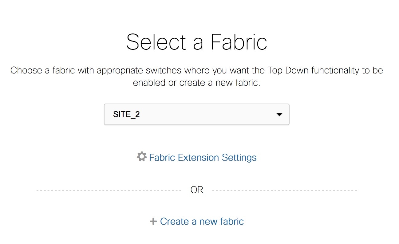
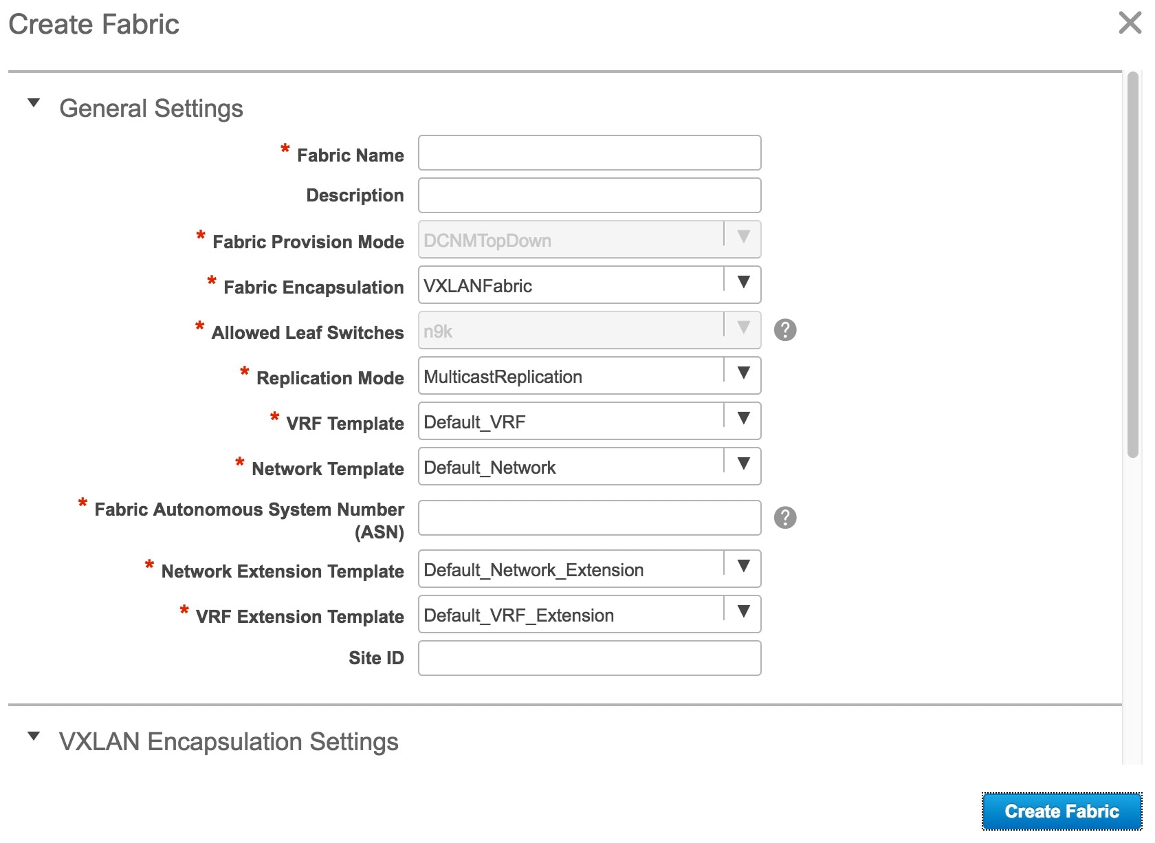
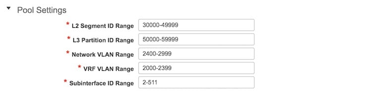
What to Do Next
Select the appropriate VXLAN fabric from the drop down list and then click on the Continue button (top right part of the screen) to create Networks and VRFs that make up the fabric. This workflow is applicable for deployment to leaf switches.
If external connectivity and network or VRF extensions need to be provisioned on the border nodes, the first step is to follow the wizard to define and provision the physical connectivity from the border nodes to the external devices. The external devices are typically part of an external fabric. External devices may be other Nexus 9000 Series switches, Nexus 7000 Series switches, or non-Nexus device (including non-Cisco devices). The provisioning of external connectivity is performed only on the border devices. The external device peer for the border node needs to be provisioned independently.
To start provisioning the external connectivity for a given fabric, select that fabric and then click on the Fabric Extension Settings option to add the Inter-Fabric interconnect links.
Creating a Network
| Step 1 | From Cisco DCNM Web Client, choose Configure > LAN Fabric Provisioning > Network Deployment. The LAN Fabric Provisioning page appears. | ||
| Step 2 | Select or create a fabric. Select the external fabric name if you want to extend traffic to an external fabric. | ||
| Step 3 | Click Continue (at the top right part of the screen). The Networks page comes up.
| ||
| Step 4 | In the Networks page, click the Add Network button. The Create Network page comes up.
If you are using the VRF view, you can switch to the Network View by clicking the Network View button. | ||
| Step 5 | Specify the
Network Information settings:
The following parameters are relevant for network extension to another fabric. | ||
| Step 6 | Specify the general network profile settings: | ||
| Step 7 | Optionally, specify the advanced profile settings by clicking the Advanced tab: | ||
| Step 8 | Click
Create Network.
The network is added to DCNM and an entry appears in the Networks page.
| ||
| Step 9 | Repeat the procedure to add relevant networks. | ||
| Step 10 | To continue the fabric provisioning process, select the corresponding check boxes next to the network names to add them to specific devices (or add and extend the networks, in case of external fabrics) and click Continue (on the top right part of the screen). You can select a maximum of 10 networks on this screen to proceed for network deployment. |
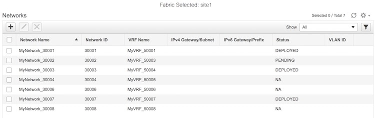
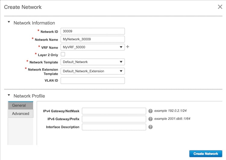
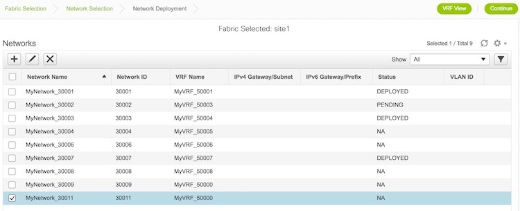
Deploying the Network
You can deploy the network after creating or selecting a network.
| Step 1 | After you
select a fabric, you need to select one or more networks. Based on the fabric
settings, network definitions will be available.
| ||||
| Step 2 | Click
Continue
(on the top right part of the screen) to start deploying the network. If you
also want to deploy other undeployed networks, select the appropriate check
boxes and then click
Continue.
The Network Deployment page (Topology View) appears
After clicking on Save, the Topology screen appears. The Leaf-82 and Leaf-84 switch icons are displayed in blue color now, indicating a Pending deployment state. Single switch configuration - To save network configurations onto a single switch, double-click a switch and save configurations in the Switches Deploy screen that comes up. | ||||
| Step 3 | Click on the
Preview (eye) icon to preview the configurations. To view network configuration
for a specific switch, select the switch and the network from the drop-down
boxes at the top of the screen. In this example, the preview displays
MyNetwork_30006 configuration on the Leaf-84 switch.
| ||||
| Step 4 | Deployment - After you verify the configurations that are generated from the profiles are correct for the selected switches, click the Deploy button to deploy the configuration. DCNM will SSH to the switches and deploy the configuration. Then, DCNM shows the deployment status with the topology by highlighting the switches with different colors. You can also select the switch and view the deployment status details. | ||||
| Step 5 | The other
view from which you can deploy configurations is the Detailed View. Click the
Detailed
View button (on the top right part of the screen) to see a tabular form,
which has similar functions as the Topology view.
You can perform the following tasks using the button options on the top left part of the table:
Click the Topology View button (on the top right part of the page) to switch to the topology view. Once you initiate the deployment process, DCNM displays the deployment status for all the networks in the fabric. You can select a switch and click the History button to view the network deployment history for the selected switch. If the role of the device is border gateway, then the network has to be extended on that border leaf switch and cannot be instantiated without extension. |

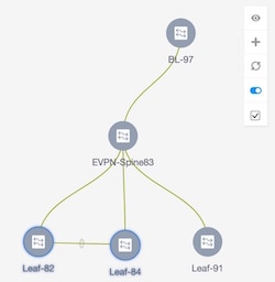
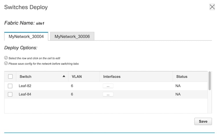
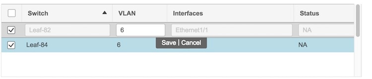
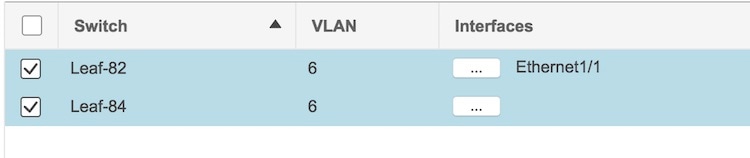 .
.
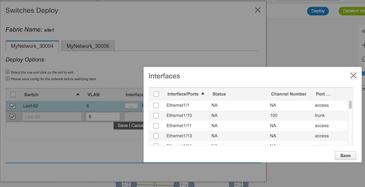 Select the relevant interface checkboxes and click on Save.
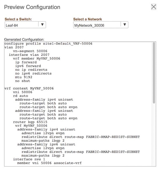
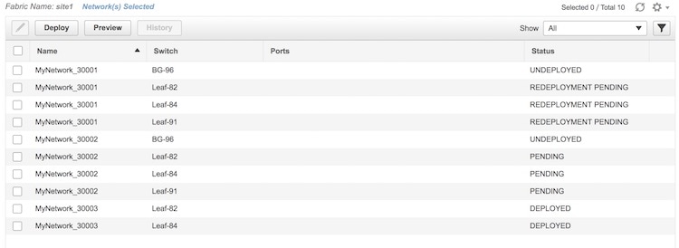

Editing a Network
| Step 1 | From Cisco DCNM Web Client, choose Configure > LAN Fabric Provisioning > Network Deployment. The LAN Fabric Provisioning page appears. |
| Step 2 | Click Continue. The Select a Fabric page that comes up. |
| Step 3 | Select the appropriate fabric from the drop-down box and click on the Continue button at the top right part of the screen. The Networks page comes up.
|
| Step 4 | Select a
network. You can only edit one network at a time.
If you are using the VRF view, you can switch to the Network View by clicking the Network View button. |
| Step 5 | Click the Edit button. The Edit Network page appears. You can add/update the Network Profile section by selecting the General and Advanced tabs. You cannot modify the Network Information section.
|
| Step 6 | After updating
information, click
Save.
Note that updating a network is not allowed while the network is being deployed. Also, the Save option will only be successful if any values are changed. In this example, the IPv4 gateway address has been updated and displayed in the Networks page.
|
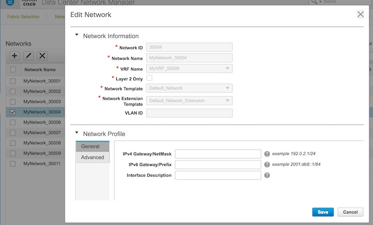
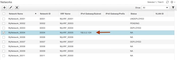
Undeploying a Network
Note | You can only undeploy networks that are deployed. |
| Step 1 | From Cisco DCNM Web Client, choose Configure > LAN Fabric Provisioning > Network Deployment. The LAN Fabric Provisioning page appears. | ||
| Step 2 | Click Continue. The Select a Fabric page comes up. | ||
| Step 3 | Select the appropriate fabric from the drop-down box and click on the Continue button at the top right part of the screen. The Networks page comes up. You can only undeploy networks whose status is DEPLOYED. For example, you can undeploy the networks MyNetwork_30003 and MyNetwork_30003.
| ||
| Step 4 | Select the networks you want to undeploy and click on the Continue button, at the top right part of the screen. The Topology screen comes up. This screen displays the fabric, the devices it is comprised of, and the connections between the devices.
| ||
| Step 5 | Double-click
on the Leaf-82 or Leaf-84 device icon (for the deployed networks). The
Switches
Deploy screen appears.
Each tab represents a network that you have chosen to undeploy (from the Networks page). The tab contains a table. Each row in the table represents a switch on which the network has presence. | ||
| Step 6 | Unselect the check box in each row, as appropriate and click on the Save button, at the bottom right part of the screen. For example, in the MyNetwork_30003 tab, if you unselect the Leaf-82 and Leaf-84 check boxes and click on Save, the network will be undeployed from those devices. | ||
| Step 7 | Select the
other tab and delete the selected network on appropriate switches, as explained
above.
Leaf-82 and Leaf-84 make up a vPC switch pair. If you click on one of the vPC switches, then the Switches Deploy screen will contain both the vPC switches since the configuration (or removal of configuration) is similar for a pair of vPC switches. | ||
| Step 8 | Alternatively,
you can click on the
Detailed
View button to undeploy networks. The network-switch combination displayed
in the
Switches
Deploy screen appears in a tabular form.
Select the appropriate network-switch combination and click the Edit button. The Switches Deploy screen will come up. Undeploy networks as per the process explained in the previous step. |
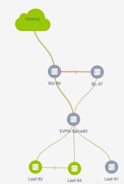
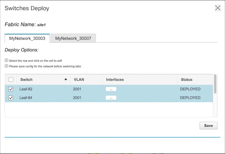
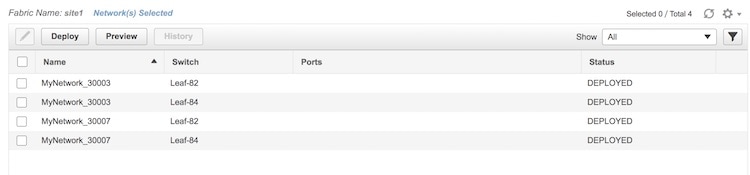
Deleting a Network
You should undeploy a network before deleting it.
| Step 1 | From Cisco DCNM Web Client, choose Configure > LAN Fabric Provisioning > Network Deployment. The LAN Fabric Provisioning page appears. |
| Step 2 | Click Continue. The Select a Fabric page comes up. |
| Step 3 | Select the
appropriate fabric from the drop-down box and click on the
Continue
button at the top right part of the screen.
The Networks page comes up.
|
| Step 4 | The delete button (X) is disabled by default. Select one or more networks you want to delete (by selecting appropriate check boxes). The delete button will be enabled. Click the delete button, and then click the Yes button that comes up to confirm network deletion. |
Creating a VRF
| Step 1 | From Cisco DCNM Web Client, choose Configure > LAN Fabric Provisioning > Network Deployment. The LAN Fabric Provisioning page appears. | ||
| Step 2 | Click Continue. The Select a Fabric page comes up. | ||
| Step 3 | Select the appropriate fabric from the drop-down box and click on the Continue button at the top right part of the screen. The Networks page comes up. | ||
| Step 4 | Click on the
VRF View
button, at the top right part of the screen. The
VRFs page
comes up.
This contains a list of VRF instances created for the site1 fabric.
| ||
| Step 5 | Click the
Create VRF (+)
button.
The
Create VRF
screen appears. The following fields are auto-populated.
| ||
| Step 6 | Click the Create VRF button. The VRF instance is added and an entry appears in the VRFs page, at the bottom. | ||
| Step 7 | Repeat the procedure to add relevant VRF instances. |
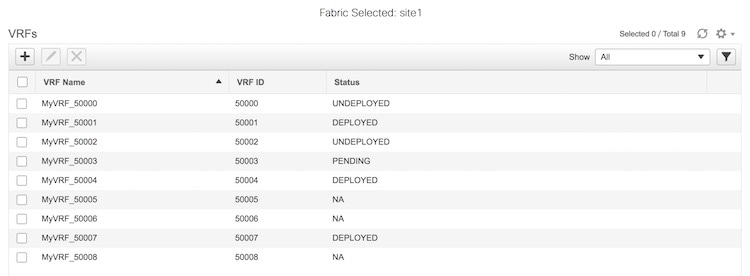
What to Do Next
Similar to deploying networks, you can deploy VRF instances after creating them, by selecting check boxes next to corresponding VRF instances and then associating them with specific devices. You can select a maximum of 10 VRF instances on this screen to proceed for deployment.
Deploying VRF Instances
When you create a VRF in the VRFs page, it gets added to the list of VRFs at the bottom of the page (MyVRF_50011 in this example). Also, the check box next to the newly created VRF is automatically selected for deployment.
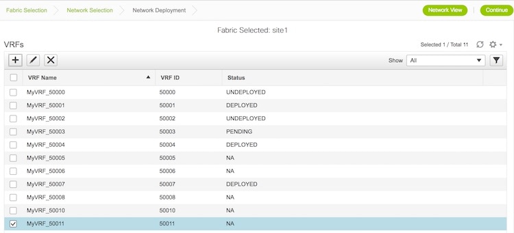
| Step 1 | Click
Continue (on the top right part of the screen) to
start deploying the VRF. If you also want to deploy other undeployed VRF
instances, select the appropriate check boxes and then click
Continue.
You can deploy one or more VRF instances at any point in time (and not just
immediately after creating a VRF) from the
VRFs page.
After clicking
Continue,
the VRF Deployment page (Topology View) appears. There are two views available:
| ||||
| Step 2 | In the
topology view, you can perform the following tasks using the options’ panel at
the right part of the screen:
| ||||
| Step 3 | You can
perform the following tasks using the button options on the top left part of
the table:
Click the Topology View button (on the top right part of the page) to switch to the topology view. | ||||
| Step 4 | Once you
initiate the deployment process, DCNM displays the deployment status for all
the VRF instances in the fabric. You can select a switch and click the History button to
view the VRF deployment history for the selected switch.
If the role of the device is border gateway, then the VRF has to be extended on that border leaf switch and cannot be instantiated without extension. |
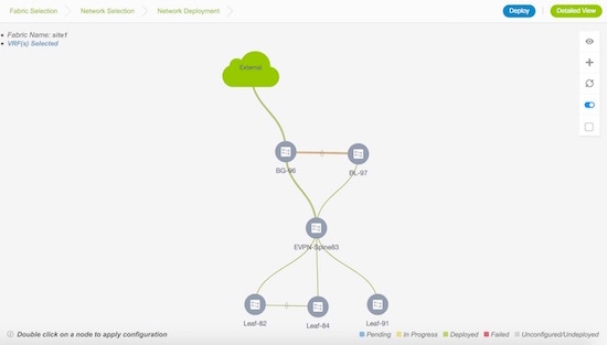
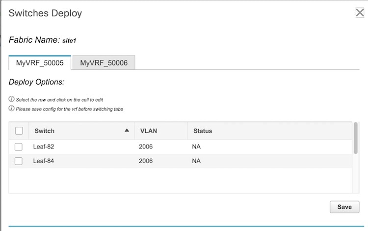 .
.
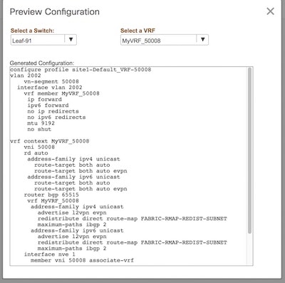
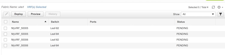

Editing a VRF
| Step 1 | From Cisco DCNM Web Client, choose Configure > LAN Fabric Provisioning > Network Deployment. The LAN Fabric Provisioning page appears. |
| Step 2 | Click Continue. The Select a Fabric page comes up. |
| Step 3 | Select the appropriate fabric from the drop-down box and click on the Continue button at the top right part of the screen. The Networks page comes up. |
| Step 4 | Click on the
VRF View
button to go to the VRFs page.
|
| Step 5 | Select a VRF. You can only edit one VRF at a time. |
| Step 6 | Click the Edit button. The Edit VRF screen appears. You cannot modify the VRF Information section. |
| Step 7 | Click
Save after updating information.
updating a VRF is not allowed while the VRF is being deployed. Also, the Save option will only be successful if any values are changed. |
Undeploying a VRF
Note | You can only undeploy VRF instances that are deployed. |
| Step 1 | From Cisco DCNM Web Client, choose Configure > LAN Fabric Provisioning > Network Deployment. The LAN Fabric Provisioning page appears. | ||
| Step 2 | Click Continue. The Select a Fabric page comes up. | ||
| Step 3 | Select the appropriate fabric from the drop-down box and click on the Continue button at the top right part of the screen. The Networks page comes up. | ||
| Step 4 | Click the
VRF View
button to see the list of VRF instances.
You can only undeploy VRF instances whose status is DEPLOYED. For example, you can undeploy MyVRF_50001 and MyVRF_50004. | ||
| Step 5 | Select the
VRFs you want to undeploy and click on the
Continue
button, at the top right part of the screen. s
The Topology screen comes up. This screen displays the fabric, the devices it is comprised of, and the connections between the devices.
Different colors denote different statuses for the selected networks, as noted in the status panel at the bottom part of your screen. The deployed devices Leaf-82 and Leaf-84 are displayed in green color because the selected VRF instances are deployed on these devices.
| ||
| Step 6 | Double-click
on the Leaf-82 or Leaf-84 device icon (for the deployed networks).
The Switches Deploy screen appears.
Each tab represents a VRF that you have chosen to undeploy (from the VRFs page). The tab contains a table. Each row in the table represents a switch on which the VRF has presence. Unselect the check box in each row, as appropriate and click on the Save button, at the bottom right part of the screen. For example, in the MyVRF_50001 tab, if you unselect the Leaf-82 and Leaf-84 check boxes and click on Save, the VRF instance will be undeployed from those devices. Select the other tab and delete the selected VRF on appropriate switches, as explained above.
Alternatively, you can click on the Detailed View button to undeploy networks. The network-switch combination displayed in the Switches Deploy screen appears in a tabular form.
Select the appropriate network-switch combination and click the Edit button. The Switches Deploy screen comes up. Delete networks as per the process explained in the previous step. |
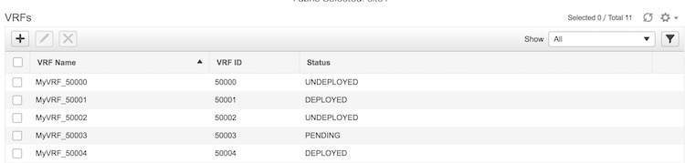
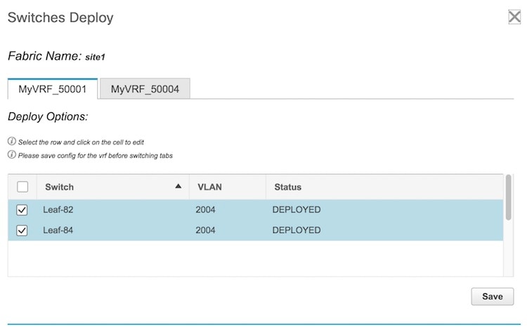
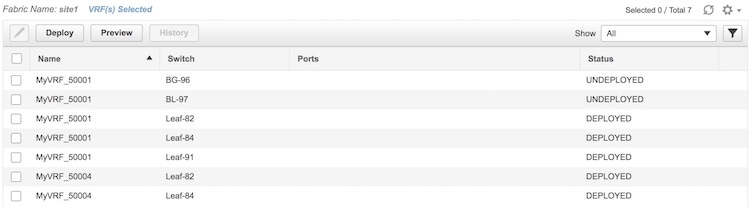
Deleting a VRF
You should undeploy a VRF before deleting it. The VRF must also be undeployed from all devices. You cannot delete a VRF when a device is under a deployment process on the same VRF. Also, a VRF can only be deleted after all the networks that use the VRF are deleted.
| Step 1 | From Cisco DCNM Web Client, choose Configure > LAN Fabric Provisioning > Network Deployment. The LAN Fabric Provisioning page appears. |
| Step 2 | Click Continue. The Select a Fabric page that comes up. |
| Step 3 | Select the appropriate fabric from the drop-down box and click on the Continue button at the top right part of the screen. The Networks page comes up. |
| Step 4 | Click on the VRF View button to see the list of VRFs. |
| Step 5 | The delete button (X) is disabled by default. Select one or more VRF instances you want to delete (by selecting appropriate check boxes). The delete button will be enabled. |
| Step 6 | Click the delete button and then click the Yes button that comes up to confirm network deletion. |
Adding Fabric Extensions
On the main topology, the border switches should be set with an appropriate role (e.g. Border Leaf or Border Gateway). The subsequent procedure describes how the inter-fabric connections between the border devices in the selected fabric and the external devices are defined.
| Step 1 | From the Cisco
DCNM Web Client, choose
Configure > LAN Fabric Provisioning > Network
Deployment. The LAN Fabric Provisioning page appears.
A new fabric can also be created through Configure > LAN Fabric Settings > LAN Fabrics. | ||||||||||
| Step 2 | Click
Continue.
The Select a Fabric page comes up.
| ||||||||||
| Step 3 | In the Select a Fabric page, click Fabric Extension Settings. The Fabric Extension screen comes up.
The Inter-Fabric Connections section lists previously created external connections. Each line represents a physical or logical connection between a border node in the selected fabric and an external device in some other fabric. For each connection, the source fabric, source device, source interface, destination fabric, destination device, and destination interface are listed along with the type of external connectivity. This section will be empty the first time you add an external connection. Two primary types of external connectivity are supported.
| ||||||||||
| Step 4 | Click on the
Add icon to add a new external connection.
The Add Inter-Fabric Connection screen appears.
| ||||||||||
| Step 5 | Fill up the fields in this page. The Source Fabric field is pre-populated in the Fabric Interconnect section. By default, the Extension Type is set to VRF_LITE. The Base template references the template that contains a one-time configuration pushed to border devices. The Extension template references the setup template that contains the configuration that will be generated and pushed to the border device to setup the corresponding inter-fabric connection. These templates are auto-populated with corresponding pre-packaged default templates based on user selections. The destination fabric that contains the external device peer must be selected. Note that based on the selection of the source device and source interface, the destination information will be auto-populated based on CDP information if available. There is extra validation performed to ensure that the destination external device is indeed part of the destination fabric. | ||||||||||
| Step 6 | Click Next to go to the Define Variables section.
Here, the IP address details of the source and destination port are pre populated from the previous step. The template variables are parsed from the templates selected in the previous step and displayed for user input. All mandatory parameters must be entered. | ||||||||||
| Step 7 | Click Next to go to the Preview and Deploy section.
Here, you can preview the configuration that will be deployed to the selected border device. Note that no configuration will be pushed to the external device itself. | ||||||||||
| Step 8 | Click
Save and
Deploy to complete the task.
This results in the configuration getting pushed to the appropriate border node. The external connection will appear in the Fabric Extension screen.
The view doesn’t auto-refresh, hence the refresh button on the top right needs to be clicked to trigger refresh. You can check the status of the deployment (Pending, Deployed, Failed etc.) in the Status column. In case of FAILED or UNDEPLOYMENT FAILED status, use the hyperlink in the Status column to check the error messages for failure. | ||||||||||
| Step 9 | For additional
inter-fabric connections, a similar set of steps is repeated. Note however, the
base configuration to the border node is only pushed once, when the first
inter-fabric connection is deployed for a given type. The connections can
either be added or deleted, they cannot be updated/edited. On successful
deployment of the inter-fabric connections, in the LAN Fabric provisioning
topology view, each inter-fabric connection will be displayed as an edge (solid
for physical or dotted for logical) between the appropriate border node and the
external fabric. Note that individual devices in the external fabric are not
shown and only a fabric/cloud icon with the fabric name is displayed.
|
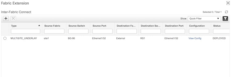
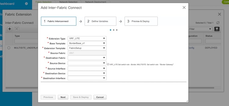
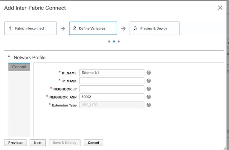
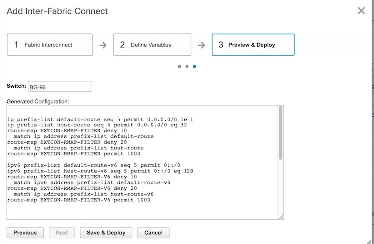
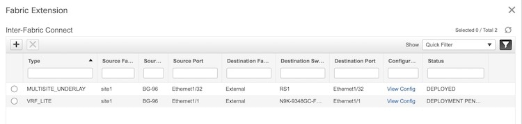
Viewing the Status of the LAN Fabric Provisioning
Cisco DCNM allows you to view the status of the LAN Fabric Provisioning and also to view which VLANs have been used on the devices within a scope.
-
You can view the status through Configure > LAN Fabric Provisioning > Status.
-
The Status column displays the status of the provisioning (Failed, Pending, or NA).
-
The VLAN Visibility button (on the top left part of the table) opens the VLAN Visibility screen. It displays the used and unused VLAN ID details for each switch. Select a switch from the list of switches to view corresponding VLAN details for the switch.
-
-
To view which VLANs have been used on the devices within a scope, use Configure > LAN Fabric Provisioning > Resource.
Migrating Cisco NFM Overlay Networks to Cisco DCNM
Cisco Nexus Fabric Manager (NFM) provides a simple point-and-click approach to build and manage both the underlay spine-leaf topology and the VXLAN overlay. Since it is fully fabric aware, it understands how the fabric should operate and can autonomously configure and maintain fabric health throughout its lifecycle. You can migrate your existing Cisco NFM deployments to Cisco DCNM to gain additional capabilities.
- Prerequisites
- Guidelines and Limitations
- Migration Workflow for Overlay Network
- Migration Workflow Status Definitions
- Using the Migration Wizard
- Viewing Migration Status
- Troubleshooting Cisco NFM to Cisco DCNM Migration
Prerequisites
-
Install Cisco DCNM if you have not done so already. For more information about installing Cisco DCNM, see the Cisco DCNM Installation Guide.
-
The NFM-managed switch nodes should be in steady and stable condition (for example, there should be no configuration updates in progress or further changes from NFM)
-
Cisco DCNM 10.4(2) enables you to migrate Cisco NFM Overlay Networks to Cisco DCNM using a migration wizard. During the migration process, you need to disable Cisco NFM so that it does not overwrite the new configuration profiles and settings deployed by Cisco DCNM.
-
No configuration changes must be made to the switches while migration is in progress.
-
You must upgrade the switch software to Cisco NX-OS version 7.0(3)I5(2) or later. For more information, see LAN Fabric Provisioning.
-
We recommend that you take a backup of the switch configurations and save them before the migration. These configurations can be used to restore the network if required.
Guidelines and Limitations
-
Cisco DCNM 10.4(2) supports only one migration to be active at a time.
-
Cisco NFM to Cisco DCNM Migration is supported for Cisco Nexus 9000 switches only.
-
When an overlay network that was deployed by NFM is migrated to DCNM, only the default templates “Default_Network” and “Default_VRF” are supported while creating the overlay network and VRF within DCNM.
Migration Workflow for Overlay Network
Cisco DCNM 10.4(2) provides a migration assistant to read and migrate the NFM-generated configurations of a switch into the LAN Fabric Provisioning functions of Cisco DCNM.
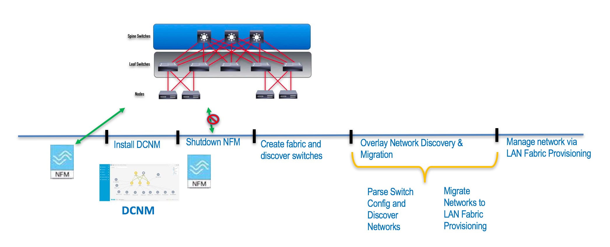
Using the migration assistant, you can perform the following steps to migrate from Cisco NFM to Cisco DCNM:
| Step 1 | Ensure that all the prerequisites have been met and Cisco DCNM is ready. |
| Step 2 | Install or upgrade Cisco DCNM to version 10.4(2). |
| Step 3 | Add your switch user credentials from the Configure > Credentials Management > LAN Credentials. |
| Step 4 | Shut down the Cisco NFM server to prevent NFM from undoing changes made by Cisco DCNM. From this point forward you do not use NFM for administering the switches. |
| Step 5 | Create a new LAN Fabric in Cisco DCNM or use an existing LAN Fabric that have matching settings listed below.
|
| Step 6 | Run the Cisco DCNM NFM Migration from Configure > LAN Fabric Provisioning > Migration menu.. This re-entrant function will automatically create equivalent overlay network entries in the Cisco DCNM Configuration > LAN Fabric Provisioning > Network Deployment entries and remove the NFM-generated CLI to migrate the switch to the DCNM mode of operation. For more information about using the Migration wizard, see the Using the Migration Wizard section. |
| Step 7 | Once the migration is complete (all networks are migrated), the Overlay networks can be managed from Configuration > LAN Fabric Provisioning > Network Deployment. |
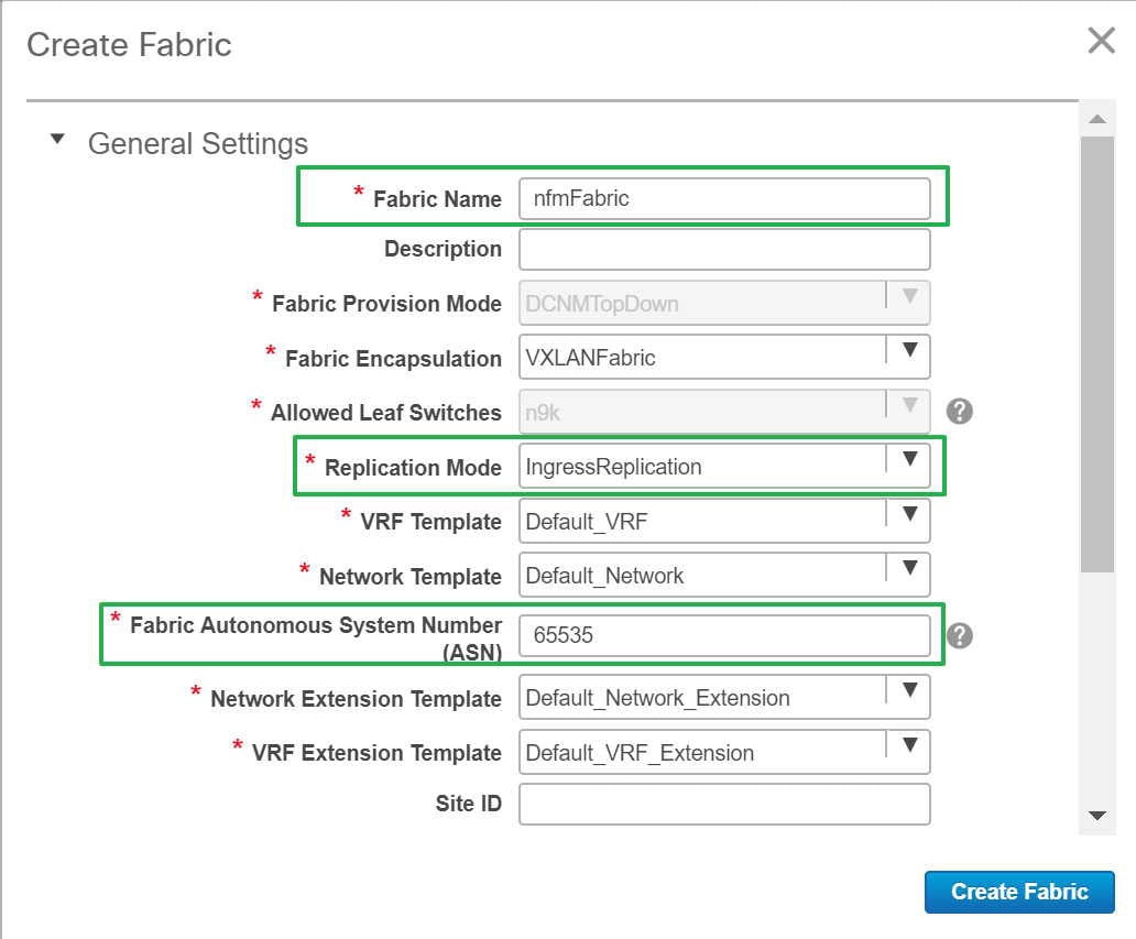
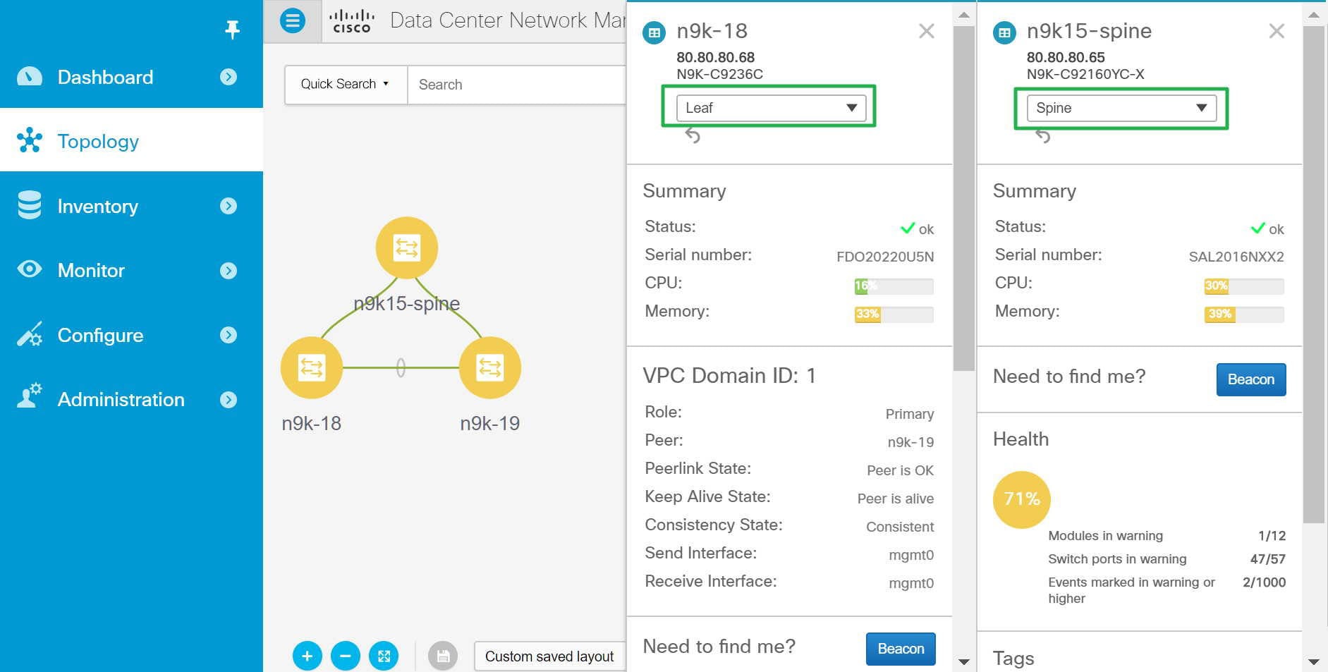
Migration Workflow Status Definitions
The following table describes the various states for the discovery or migration workflow.
Discovery-related Status Definitions:
|
Status |
Definition |
|---|---|
|
DISCOVERY INITIATED |
A discovery has been triggered and waiting to start |
|
DISCOVERY IN PROGRESS |
The discovery is active |
|
DISCOVERY FAILED |
The previous discovery failed |
|
DISCOVERY ABORT INITIATED |
An attempt to abort or cancel an active discovery has been initiated |
|
DISCOVERY ABORTED |
The previous discovery has been aborted |
|
DISCOVERY COMPLETED |
The discovery has been completed successfully |
Migration-related Status Definitions:
|
Status |
Definition |
|---|---|
|
MIGRATION INITIATED |
Migration has been initiated for a set of network(s) |
|
MIGRATION IN PROGRESS |
Migration is in progress for a set of network(s) |
|
MIGRATION FAILED |
The previous migration failed |
|
MIGRATION ABORT INITIATED- |
An attempt to abort or cancel an active migration has been initiated |
|
MIGRATION ABORTED |
Migration has been aborted |
|
MIGRATION PENDING |
There are more networks waiting to be migrated |
|
MIGRATION COMPLETED |
All the networks have been migrated |
Network Migration Status Definitions
The following table describes the various states of the network migration workflow:
|
Status |
Definition |
|---|---|
|
DISCOVERED |
The network has been discovered from the switch configurations |
|
SWITCH MIGRATION PREPARATION IN PROGRESS |
The switch where the network is present is being prepared |
|
SWITCH MIGRATION PREPARATION FAILED |
The switch preparation step failed |
|
NETWORK MIGRATION PREPARATION IN PROGRESS |
The L3 network is being prepared for migration |
|
NETWORK MIGRATION PREPARATION FAILED |
The L3 network preparation step failed |
|
NETWORK CREATION IN PROGRESS |
The LAN Fabric Provisioning Network entry is being created |
|
NETWORK CREATION FAILED |
The LAN Fabric Provisioning Network entry creation failed |
|
NETWORK DEPLOYMENT IN PROGRESS |
The LAN Fabric Provisioning Network deployment is in progress |
|
NETWORK DEPLOYMENT FAILED |
The LAN Fabric Provisioning Network deployment failed |
|
ORIGINAL CONFIGURATION REMOVAL PENDING |
The LAN Fabric Provisioning Network deployment is successful and waiting to remove the original NFM configured CLIs |
|
ORIGINAL CONFIGURATION REMOVAL IN PROGRESS |
The removal of the original NFM configured CLIs is in progress |
|
ORIGINAL CONFIGURATION REMOVAL RECOVERABLE FAILURE |
The removal of the original NFM configured CLIs failed, but, can be retried on a future attempt after fixing any underlying issues |
|
ORIGINAL CONFIGURATION REMOVAL FAILED |
The removal of the original NFM configured CLIs failed. The failure reason must be reviewed and manual corrective action must be taken. Please review the nature of the failure(s). If some of the configuration CLIs were partially applied, please reapply the failed and rest of the CLIs manually on the switch(es). |
|
COMPLETED |
The network was migrated successfully |
Network Migration History Definitions:
A network migration history will contain the following items and can be used to review detailed information.
|
Status |
Definition |
|---|---|
|
Switch Migration Preparation |
Provides status of preparing the switch for the migration. This action is performed only once per switch, but, will show up in all network histories |
|
Network Migration Preparation |
Provides status of the network migration preparations. This entry will be present for L3 network only |
|
Deploy Network |
Provides status of the LAN Fabric Network provisioning |
|
Unapply Manual Configurations |
Provides status of removing the network overlay CLIs configured by NFM. Note: This does not lead to any loss of configuration since LAN Fabric Provisioning uses configuration profiles. |
Using the Migration Wizard
Note | It is important that the discovered networks and data are verified before a migration is attempted. Once the first network is migrated (Migration Phase) it is not possible to go back to the Discovery Phase to make changes. |
Cisco NFM supports single fabric, whereas Cisco DCNM supports multiple fabrics, so the original NFM-deployed fabric becomes one fabric among all the Cisco DCNM-managed fabrics.
Note | It is important that no configuration or network changes are made to the switches until the migration is completed. Any out-of-band configuration changes can interfere with the migrations and can cause significant network issues. |
-
Preparing the switch for migration to DCNM Top-Down managed networks.
-
Removing the original configuration that existed on the switch prior to the deployment
Note
The migration status will be presented to you for review.
To use the Migration wizard perform the following steps:
| Step 1 | Launch Cisco DCNM Web Client. |
| Step 2 | From the menu bar, choose Configure > LAN Fabric Provisioning > Migration. |
| Step 3 | Select the
fabric that have the NFM fabric switches, and then click
Continue.
The discovery process auto-generates the network name of the form as Auto_Net_VLANxxx_VNIyyyyy . Cisco DCNM will retrieve the running configuration from the switch(es), parse the configurations to discover the VXLAN overlay data. At this point, the migration is considered to be in progress. The parsing occurs in the background and the page refreshed with the discovered networks. One cannot proceed further till the discovery process is completed. The ‘Continue’ button and check boxes will be disabled while discovery is in progress. The discovered networks are persisted till one of the following event occurs:
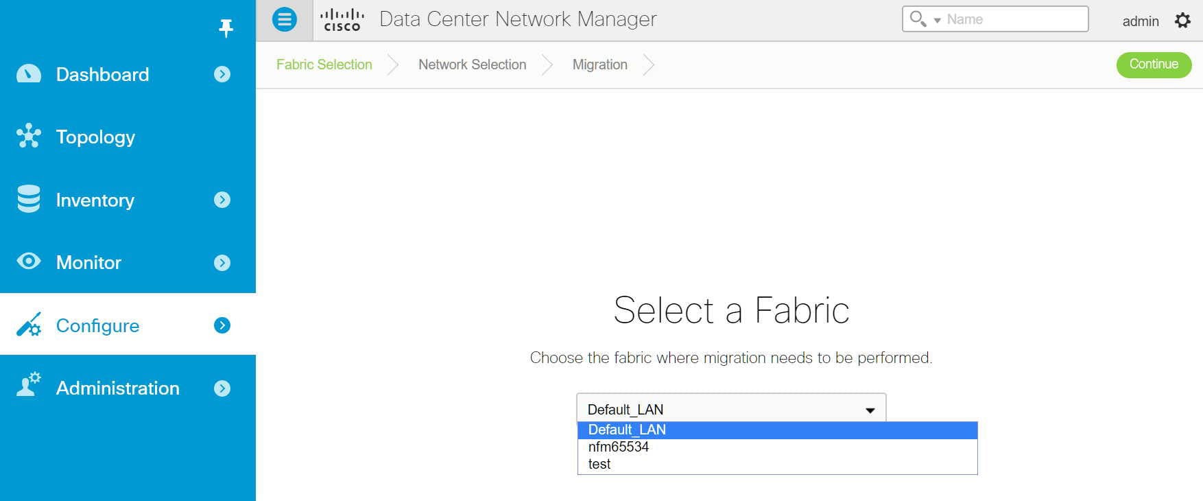 |
| Step 4 | Select the
network(s) that you wish to migrate by clicking the
Continue button.
The Network Selection page displays the following buttons:
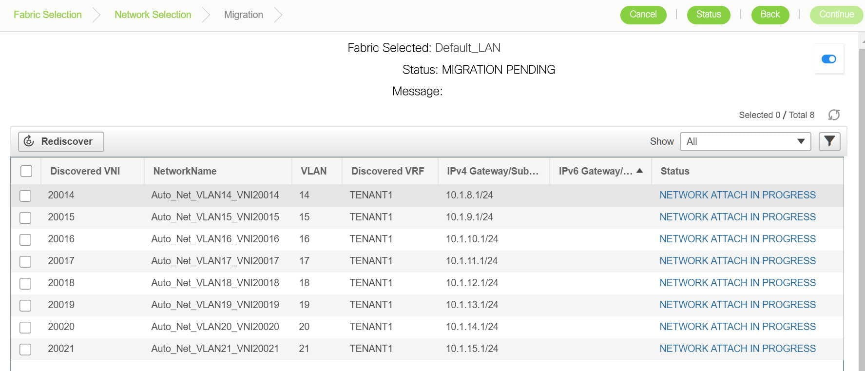
|
| Step 5 | Select the
network(s) that need to be migrated and click the
Continue button.
The
following page that appears has some additional options that allow you to
perform the following functions:
|
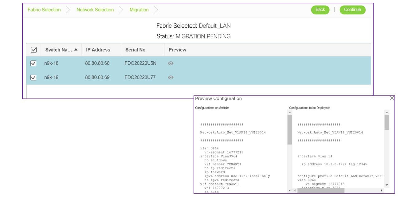
Viewing Migration Status
| Step 1 | In the Migration page, click the Status button. This status page appears when you click the Status button. This reports the cumulative status of all migrations performed so far.
|
| Step 2 | You can click the hyperlinks to view migration history and status.
|
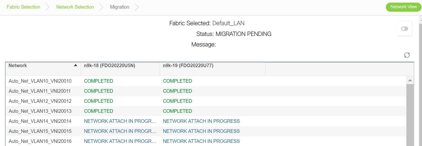
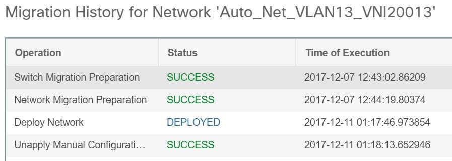
Troubleshooting Cisco NFM to Cisco DCNM Migration
The Migration workflow involves multiple steps and some unexpected issues that might be encountered while migrating Cisco NFM to Cisco DCNM.
Issues (if any) will be indicated with an appropriate "FAILED" status for the individual network(s) or the entire workflow.
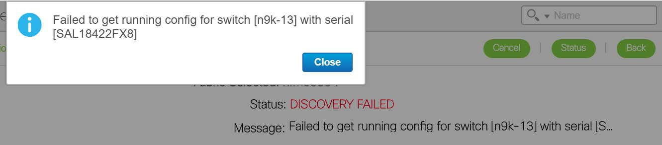
Network Migration Failures
-
Go to the Migration page.
-
Identify the network and switch that has encountered the failure and click on the Status hyperlink. The resulting popup will show the status of each migration step.
Further details can be obtained by clicking the appropriate hyperlinks.
Additional details can be obtained by reviewing the log files.
Migration Workflow Failures
The migration status will indicate a FAILURE. Additional details can be obtained by reviewing the log files.
Detailed Logs
The migration workflow logs are maintained on DCNM. You can review them using this procedure.
-
SSH into DCNM
-
cd /usr/local/cisco/dcm/fm/logs
-
ls -ltr migrate.log*
Multiple logs files can exist (because of rollover) with the most recent one being 'migrate.log'
Example log file:
[root@dcnm84 logs]# pwd
/usr/local/cisco/dcm/fm/logs
[root@dcnm84 logs]# ls -ltr migrate.log*
-rw-r--r-- 1 root root 10485678 Nov 20 22:01 migrate.log.3
-rw-r--r-- 1 root root 10484761 Nov 20 23:36 migrate.log.2
-rw-r--r-- 1 root root 10485721 Nov 21 03:03 migrate.log.1
-rw-r--r-- 1 root root 7414428 Nov 21 05:36 migrate.log
Note | The logs are for review purpose only. Do not attempt to delete or make changes to them. |
Contact Cisco TAC if further assistance is needed.
LAN Fabric Auto-Configuration
The LAN Fabric Auto-Configuration menu includes the following submenus:
- LAN Fabric Auto-Configuration
- Organizations
- Partitions
- Networks
- Profiles
- Border Leaf Device Pairing
- Extended Partitions
- End Hosts
LAN Fabric Auto-Configuration
This feature automates network provisioning and provides a new layer of automation integration in which the data center fabric-switching infrastructure is automatically provisioned for the physical or virtual workload that is being instantiated.
Note | These features appear on your Cisco DCNM Web Client application only if you have deployed the DCNM installer in the Unified Fabric mode. |
The following icons are listed at the menu bar of the window to customize the view of the information in the window:
|
Field/Icons |
Description |
|
|---|---|---|
|
Organizations Section |
||
|
Organization/Partition Name |
Specifies the organization or the partition name. |
|
|
Description |
Specifies the description for the organization. |
|
|
Partition ID |
Specifies the partition ID to be associated with the partition. |
|
|
Orchestration Engine |
Specifies the Orchestrator name for the organization. |
|
|
Service Node IP Address |
Specifies the IP address for the service node for a partition |
|
|
Edge Router ID |
Specifies the Edge Router ID. |
|
|
Extension Status |
Specifies if the extension is enabled or disabled. |
|
|
Profile |
Specifies the default profile used. |
|
|
Networks Section |
||
|
Network Name |
Specifies the name to identify the network. |
|
|
Partition Name |
Allows you to select the partition to be applied for the network. |
|
|
Segment ID |
Specifies the segment ID to be used for partition extension. |
|
|
Mobility Domain |
VLAN ID |
Specified the VLAN ID for the mobility domain. |
|
Mobility Domain ID |
Allows you to select the mobility domain ID from the drop-down list. |
|
|
Profile Name |
Specifies the default profile used. |
|
|
DHCP Scope |
Subnet |
Specifies the subnet for the network. |
|
Gateway |
Specifies the gateway for the network. |
|
|
IP Range |
Specifies the IP address range available for the network. |
|
|
Add |
Allows you to add Organization, Partition, or Network. |
|
|
Edit |
Allows you to edit Organization, Partition, or Network. |
|
|
Delete |
Allows you to delete Organization, Partition, or Network. |
|
|
Enable Extension |
Allows you to enable the extension for the selected Organization. |
|
|
Disable Extension |
Allows you to disable the selected extension. |
|
|
Deploy Configuration |
Allows you to deploy the network for the selected partition. |
|
|
Undeploy Configuration |
Allows you to undeploy the network configuration. |
|
|
Refresh |
Refreshes the list of items in the view. |
|
|
Show Filter |
Filters list of items based on the defined value for each column. |
|
|
|
Prints the list of Organizations or Networks along with their details. |
|
|
Export |
Exports the list of items and their details to a Microsoft Excel spreadsheet. |
|
|
Maximize |
Allows you to maximize the view for Organizations or Networks. |
|
Fabric provides the following configuration options:
Organizations
You can create profiles from the Cisco DCNM Web Client > Configure > LAN Fabric Auto-Configuration > Organizations.
Adding an Organization
Editing an Organization
Deleting an Organization
Note | You must delete all partitions under an organization before deleting the organization. |
Partitions
You can create profiles from the Cisco DCNM Web Client > Configure > LAN Fabric Auto-Configuration > Partitions.
Adding a Partition
| Step 1 | From the menu bar, select Configure > LAN Fabric Auto-Configuration > Partitions. |
| Step 2 | Specify the Name for the partition.
Ensure that you have selected an organization from the Organizations drop-down list before adding partitions. |
| Step 3 | Specify the VRF name and provide description for the partition. |
| Step 4 | Specify the Edge Router ID for the partition.
Select the checkbox if you choose to extend the partition across the fabric. If you do not select the checkbox, this partition will not be extended across the Fabric. |
| Step 5 | Specify the DNS Server and the Secondary DNS server for the partition. |
| Step 6 | From the drop-down list, select the default Profile Name.
The values for the Profile Parameters are auto-populated based on the default Profile Name. |
| Step 7 | Click OK to configure the partition. |
Editing a Partition
Deleting a Partition
Note | You must delete all networks under the partition before deleting the partition. |
Networks
You can create profiles from the Cisco DCNM Web Client > Configure > LAN Fabric Auto-Configuration > Networks.
Adding a Network
| Step 1 | From the menu bar, select Configure > LAN Fabric Auto-Configuration > Networks. | ||
| Step 2 | Specify the VRF Name for the partition.
The VRF Name must be of the format organizationName:partitionName. | ||
| Step 3 | Specify the Network Name to identify the network. | ||
| Step 4 | Specify the Multicast Group Address.
| ||
| Step 5 | Select the Network Role from the drop-down list based on the type of the network. | ||
| Step 6 | In the Network ID section, choose one of the following:
| ||
| Step 7 | In the DHCP Scope section, specify the IP Range. | ||
| Step 8 | Use the drop-down to select the Profile. | ||
| Step 9 | Specify the Profile parameters. | ||
| Step 10 | Specify the Service Configuration parameters. | ||
| Step 11 | Click Add. |
Editing a Network
Deleting a Network
| Step 1 | From the menu bar, select Configure > LAN Fabric Auto-Configuration > Networks. | ||
| Step 2 | Select a network from the list and click the Delete icon. | ||
| Step 3 | Click
Yes to confirm.
|
Profiles
You can create profiles from the Cisco DCNM Web Client > Configure > LAN Fabric Auto-Configuration > Profiles.
The following icons are listed at the menu bar of the window to customize the view of the information in the window:
|
Field |
Description |
|---|---|
|
Name |
Specifies the name of the profile. |
|
Type |
Specifies the type of the profile. |
|
Sub Type |
Specifies the sub type of profiles differentiate profile categories. |
|
Description |
Displays the description for the profile. |
|
Forwarding Mode |
Specifies the mode for forwarding. |
|
Editable |
Specifies if the profile parameters are editable or not. |
|
Last Modified Time |
Displays the last time when the profile was modified. |
|
Field |
Description |
|---|---|
|
Organization Name |
Displays the name of the Organization. |
|
Partition Name |
Displays the name of the partition created in the organization. |
|
VRF Name |
Species the VRF name for the profile. |
|
Segment ID |
Specifies the Segment ID for the profile instance |
|
VLAN ID |
Specifies the VLAN ID for the profile |
|
Network Name |
Specifies the network name for the profile. |
Profiles provide the following configuration options:
Adding a profile
| Step 1 | From the menu bar, select Configure > LAN Fabric Auto-Configuration > Profiles. | ||
| Step 2 | In the Add
Profile window, specify the
Name and
Description of
the profile.
| ||
| Step 3 | Use the
drop-down, select the
Type of the
Profile.
| ||
| Step 4 | From the drop
down, select
Sub
Type. Sub Type of profiles differentiate profile
categories, such as :
The following subtypes are supported:
| ||
| Step 5 | Use the
drop-down to select the Forwarding Mode. The following values are supported:
| ||
| Step 6 | Enter the Profile Content from collection of CLI commands to discover a specific configuration. | ||
| Step 7 | Click Add. |
Editing a Profile
Delete a Profile
Editing a Profile Instance
Border Leaf Device Pairing
This feature allows you to pair Border Leaf with the Edge Router and specify device associated configurations such as interface between Border Leaf and Edge Router. DCNM selects appropriate Border Leaf/Edge Router pairs during partition (VRF) extension.
The following icons are listed at the menu bar of the window to customize the view of the information in the window:
|
Field |
Description |
|---|---|
|
Edge Router/Border Leaf |
Specifies the Name of the Edge Router or the connected Border Leaf. |
|
IP Address |
Specifies the IP address of the Border Leaf/Edge Router. |
|
Interface Name/Port Channel |
Specify the interface name or port channel between Border Leaf and Edge Router. |
|
Profile Name |
Specifies the default profile name. |
|
Type |
Specifies if the device is an Edge Router configuration or a Border Leaf configuration. |
|
Partition Utilization |
Specifies the partitions utilized and the maximum partitions available for the device. |
|
Add |
Allows you to add a Border Leaf/Edge Router. For more information, see Creating an Edge Router. |
|
Edit |
Allows you to edit a Border Leaf/Edge Router. |
|
Delete |
Allows you to delete a Border Leaf/Edge Router. For more information, see Deleting Edge Router/Border leaf devices. |
|
View Profile |
Allows you to view the profile created |
|
Refresh |
Refreshes the list of switches. |
|
Show Filter |
Filters list of switches based on the defined value for each column. |
|
|
Prints the list of devices and their details. |
|
Export |
Exports the list of devices and their details to a Microsoft Excel spreadsheet. |
- Creating an Edge Router
- Connect New Border leaf to the Edge Router
- Deleting Edge Router/Border leaf devices
Creating an Edge Router
| Step 1 | From the menu bar, select Configure > LAN Fabric Auto-Configuration > Border Leaf Pairing. |
| Step 2 | Click Add. Select Edge Router. |
| Step 3 | To configure
the Edge Router, perform the following steps.
|
| Step 4 | To configure a
Border PE, perform the following steps
|
| Step 5 | Click OK to save the configuration. |
Connect New Border leaf to the Edge Router
| Step 1 | From the menu bar, select Configure > LAN Fabric Auto-Configuration > Border Leaf Pairing. | ||||||||||||||
| Step 2 | Click Add. Select Border Leaf. | ||||||||||||||
| Step 3 | Define the parameters for the Border leaf configuration and edge
router configuration for pairing.
| ||||||||||||||
| Step 4 | Click OK to connect the new border leaf device to the Edge router. |
Deleting Edge Router/Border leaf devices
Extended Partitions
This screen lists the extended partitions, selected Border Leaf/Edge Router pairs, and their corresponding profiles and configurations. From the menu bar, select Configure > LAN Fabric Auto-Configuration > Extended Partitions.
The following icons are listed at the menu bar of the window to customize the view of the information in the window:
|
Field |
Description |
|---|---|
|
VRF |
Specifies the VRF name for the extended partition. |
|
Organization |
Specifies the name of organization which the extended partition belongs to. |
|
Partition |
Specifies the name of the partition that is extended. |
|
Redundancy Factor |
Specifies the run-time redundancy factor for that partition extension. |
|
Edge Router |
Specifies the name of the Edge Router. |
|
Edge Router IP Address |
Specifies the IP address of the Edge Router device. |
|
Edge Router Profile |
Specifies the default profile for the edge router. |
|
Border Leaf (BL) |
Specifies the name of the Border Leaf device |
|
BL IP Address |
Specifies the IP address of the Border Leaf device. |
|
BL Profile |
Specifies the default profile for the border leaf device. |
End Hosts
Cisco DCNM provides repository for end host MAC address to segment ID mapping, which can be used for end hosts such as auto-configuration of the bare-metal server.
The following table describes the fields that appear on Configure > LAN Fabric Auto-Configuration > End Host.
|
Field |
Description |
|---|---|
|
End Host ID |
Specifies the ID for this end host. The value is a MAC address if End Host Type is MAC Address. |
|
End Host Type |
Specifies the type for this end host. The default type is MAC Address. |
|
End Host Name |
Specifies a name for this end host. |
|
Connection Port Mode |
Select the connection port mode from the drop down list. The options available are: |
|
Segment ID |
Specifies the segment ID for this end host. |
This section contains the following:
Adding End Hosts
Perform the following task to add end hosts.
Editing End Hosts
Perform the following task to edit end hosts.
Deleting End Hosts
Perform the following task to delete end hosts.
Endpoint Locator
The Endpoint Locator (EPL) feature allows real-time tracking of endpoints within a data center. This includes tracing the network life history of an endpoint as well as getting insights into the trends associated with endpoint additions, removals, moves etc. An endpoint is anything with a IP and MAC address. In that sense, an endpoint can be a virtual machine (VM), container, bare-metal server, service appliance etc.

Note | Endpoint Locator is currently only supported for VXLAN BGP EVPN fabric deployments and DFA (BGP L3VPN) based fabric deployments. It is not supported for access aggregation based deployments. |
EPL relies on BGP updates to track endpoint information. Hence, the DCNM needs to peer with the BGP Route-Reflector (RR) to get these updates. For this purpose, IP reachability from the DCNM to the RR is required.
Some key highlights of the Endpoint Locator are:
-
Support for dual-homed and dual-stacked (IPv4 + IPv6) endpoints
-
Support for up to 2 BGP route reflectors
-
Support for real-time and historical dashboards for insights such as endpoint lifetime, network, endpoint, VRF daily views, and operational heat map
-
Support for high availability
-
Support for endpoint data stored for up to 180 days, amounting to a maximum of 5 G storage space
-
Support for optional flush of the endpoint data to start afresh
-
Supported scale: 10K endpoints
For more information about EPL, refer to the following sections:
- Configuring Endpoint Locator
- Adding High Availability Node to Endpoint Locator Configuration
- Configuring Endpoint Locator in DCNM High Availability Mode
- Disabling Endpoint Locator
- Troubleshooting Endpoint Locator
Configuring Endpoint Locator
With the DCNM OVA or ISO form factor, the default installation occurs with 2 interfaces—eth0 interface for external access to the DCNM and eth1 interface that is used primarily for fabric management. In most deployments, the eth1 interface is part of the same network on which the mgmt0 interfaces of the Nexus switches reside (Out-of-band or OOB network). This allows DCNM to perform out-of-band management of these devices including POAP.
For EPL, BGP peering from the DCNM to the BGP Route-Reflector is required. Since the BGP process on Nexus devices typically runs on the non-management VRF, specifically default VRF, there is a requirement to have in-band IP connectivity from the DCNM to the fabric. For this purpose, a third interface, ethx, is required. This is a pre-requisite for enabling the EPL feature. For the OVA deployment, addition of a new interface does not require a restart of the DCNM VM. Once the vnic is added to the DCNM VM, the corresponding veth interface gets created and shows up in the VM as the appropriate ethx interface.
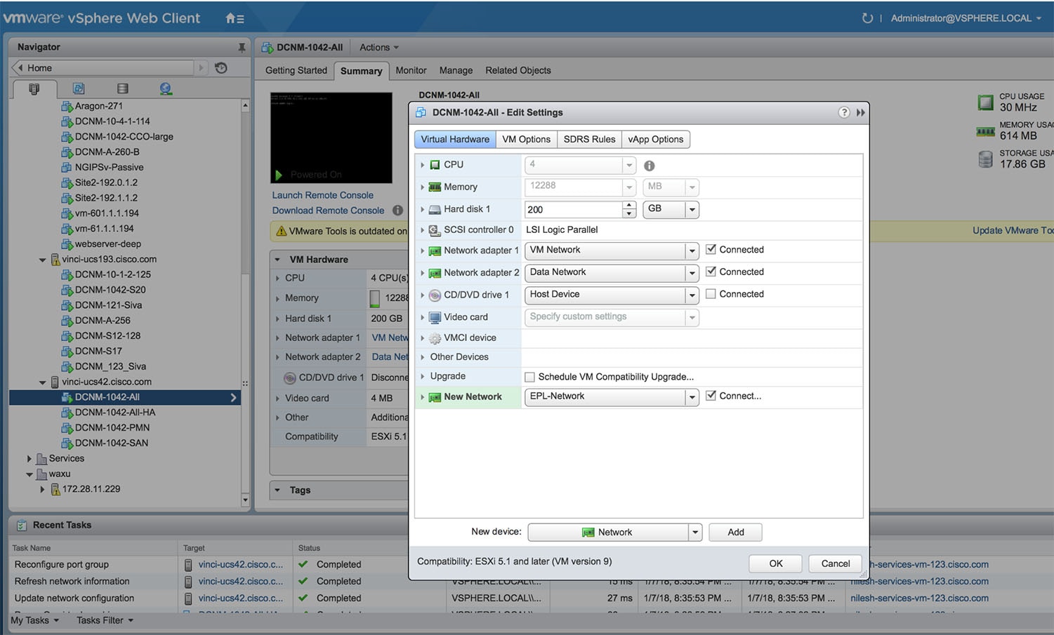
Once in-band connectivity is established between server (physical or virtual) on which DCNM is running and the fabric, BGP peering can be established. There is a simple 4-step wizard for enabling EPL. The 4 steps are highlighted below:
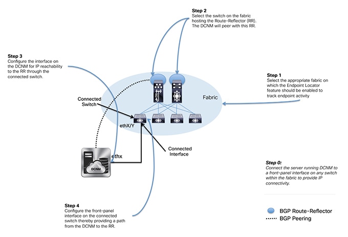
There are 2 sub-modes for configuring EPL which differ in how the network fabric will be configured to do BGP peering from the RR to the DCNM. These specifically differ in the options selected and entered in step 4. These sub-modes are:
-
Fully-automated—In this option, as the name suggests, all the configuration on the network fabric and the DCNM is done as part of EPL enablement. Here, the assumption is that the server on which DCNM is running is directly attached to a ToR/leaf that in turn provides reachability to the RR. In this option, when EPL is enabled, the interface on the ToR/leaf is automatically configured as a routed interface and the corresponding subnet prefix reachability is redistributed into the fabric via the appropriately configured IGP within the fabric. In addition, the RR(s) are configured to accept DCNM as a BGP peer for distributing endpoint information.
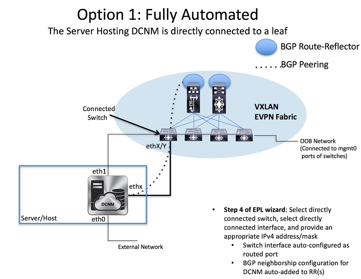
-
Semi-automated—In this option, only the DCNM is configured appropriately for EPL. The assumption is that there is IP reachability already pre-established from the DCNM to the RR, hence an appropriate next-hop IP address should be provided in step 4 for this purpose. In addition, appropriate BGP neighborship configuration must be added to the RRs to accept DCNM as a peer. Note that, DCNM queries the BGP RR to glean information for establishment of the peering (e.g. ASN, RR IP etc.).
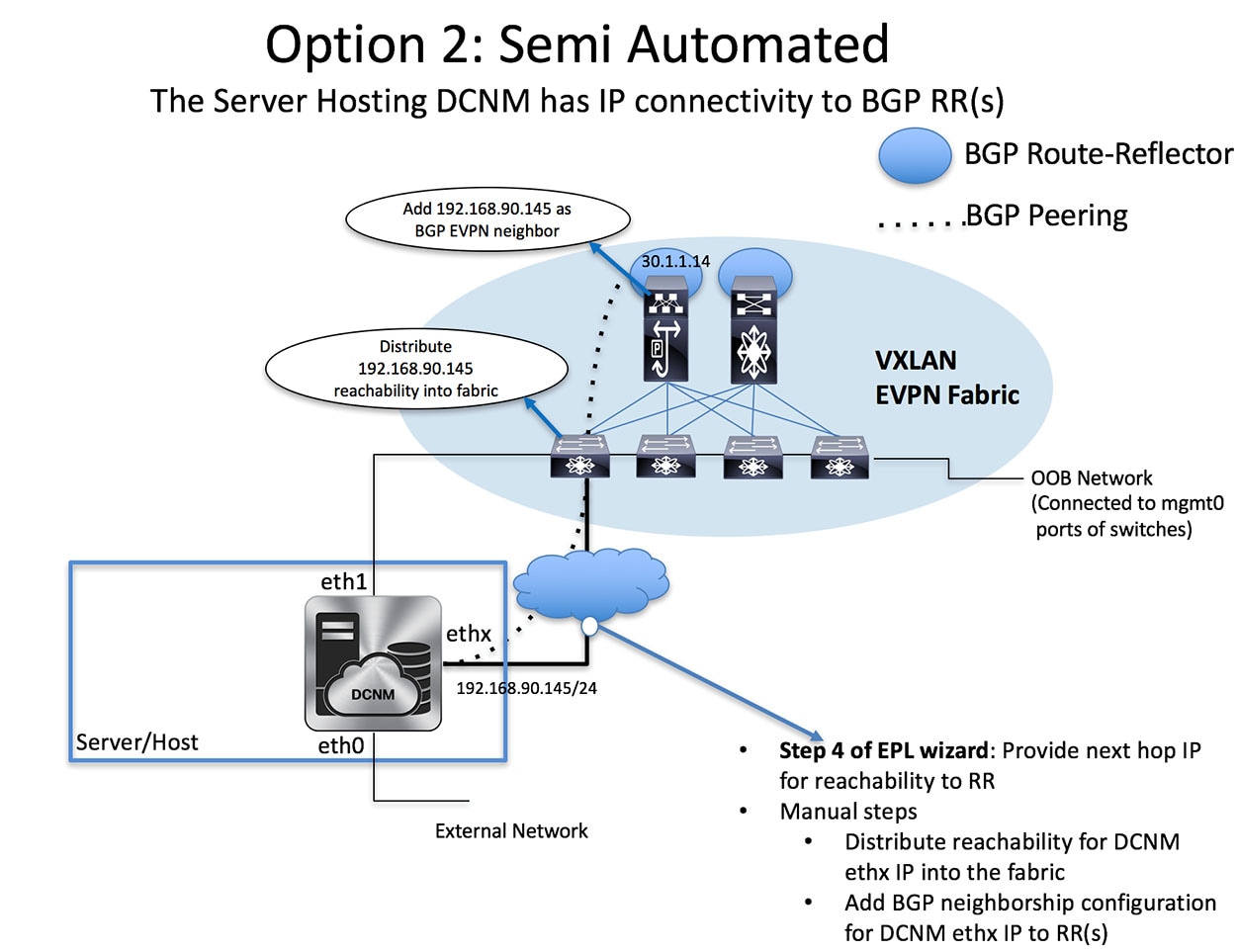
| Step 1 | From the menu bar, choose Configure > Endpoint Locator > Configure. The Endpoint Locator page appears with a See how it works help link.
|
| Step 2 | Click Continue. |
| Step 3 | Select the appropriate fabric on which the Endpoint Locator feature should be enabled to track endpoint activity.
EPL can only be enabled for one fabric (this can be DFA or EVPN).
|
| Step 4 | Select the switch(es) on the fabric hosting the Route-Reflector (RRs). DCNM will peer with the RR(s).
|
| Step 5 | Configure the interface on DCNM for IP reachability to the RR. Select the appropriate interface ethx and provide the IP address and subnet mask for that interface. Through this interface, the in-band connectivity is established from the DCNM to the RR.
|
| Step 6 | In the next step, a selection must be made by checking (fully-automated mode) or unchecking the “Configure my fabric” (semi-automated mode) option. First, we will look at the semi-automated mode which is likely the preferred option in scenarios where there is no direct connectivity between the DCNM server and the ToR. In the semi-automated mode, the “Configure my fabric” option is un-checked. Hence, only the next-hop IP address for reachability to the RR must be specified. Recall that any configuration on the network fabric for reachability between the RR and the DCNM must be done separately in this case.
|
| Step 7 | The last step provides a summary of the information entered in the previous steps. The wizard view allows navigation to any particular step whereby one can make necessary changes/edits. In this step, one must specify whether additional information such as PORT, VLAN, VRF etc. is required when enabling the EPL feature. If the No option is selected, then this information will not be collected and reported by EPL.
However, if the Yes option is selected in the drop down, a warning pop-up appears that feature NX-API must be supported and enabled on the switches/ToRs/leafs to gather this information. Otherwise this additional information cannot be fetched or reported.
|
| Step 8 | Once the appropriate selections are made and various inputs have been reviewed, click on the Continue button to enable EPL. A progress bar will appear indicating the status of the EPL feature enable process.
If there are any errors during the enablement, the enable process will abort and the appropriate error message will be displayed. Otherwise, EPL will be successfully enabled and on clicking the Ok, the screen will be automatically redirected to the EPL dashboard.
|
| Step 9 | In case in Step 4, the “Configure my fabric” option is selected/checked, then the user has opted for the fully-automated mode for enabling EPL. Recall that in this case the DCNM server must be directly attached to a ToR/leaf switch. The appropriate connected switch and port on the other side of the DCNM ethx interface must be selected. The specified IP address will be configured on the selected interface on the connected switch.
In this case, the review step will look as follows:
When the Endpoint Locator feature is enabled, there are a number of steps that occur in the background. DCNM will contact the selected RR(s) and determine the ASN, determine whether the fabric is L3VPN or EVPN enabled, and also determine the interface IP that is bound to the BGP process. Also, appropriate BGP neighbor statements are added on the RR(s), to get it ready to accept the BGP connection that will be initiated from the DCNM. The neighbor address will be the same as that of the ethx interface specified in step 2. DCNM will configure the ethx interface that provides in-band connectivity to the fabric with the appropriate IP address provided in step 2. In order to provide reachability to the RR, a static route will be added to DCNM. If the “Configure my fabric” option is selected during enabling EPL, the connected switch and associated interface specified in step 2 will be configured as a routed interface. This ensures that DCNM has connectivity to the RR. Once EPL is successfully enabled, the user is automatically redirected to the EPL dashboard that depicts operational and exploratory insights into the endpoints that are present in the fabric. For more information, please refer to the Section “Exploring Endpoint Locator Details”. |
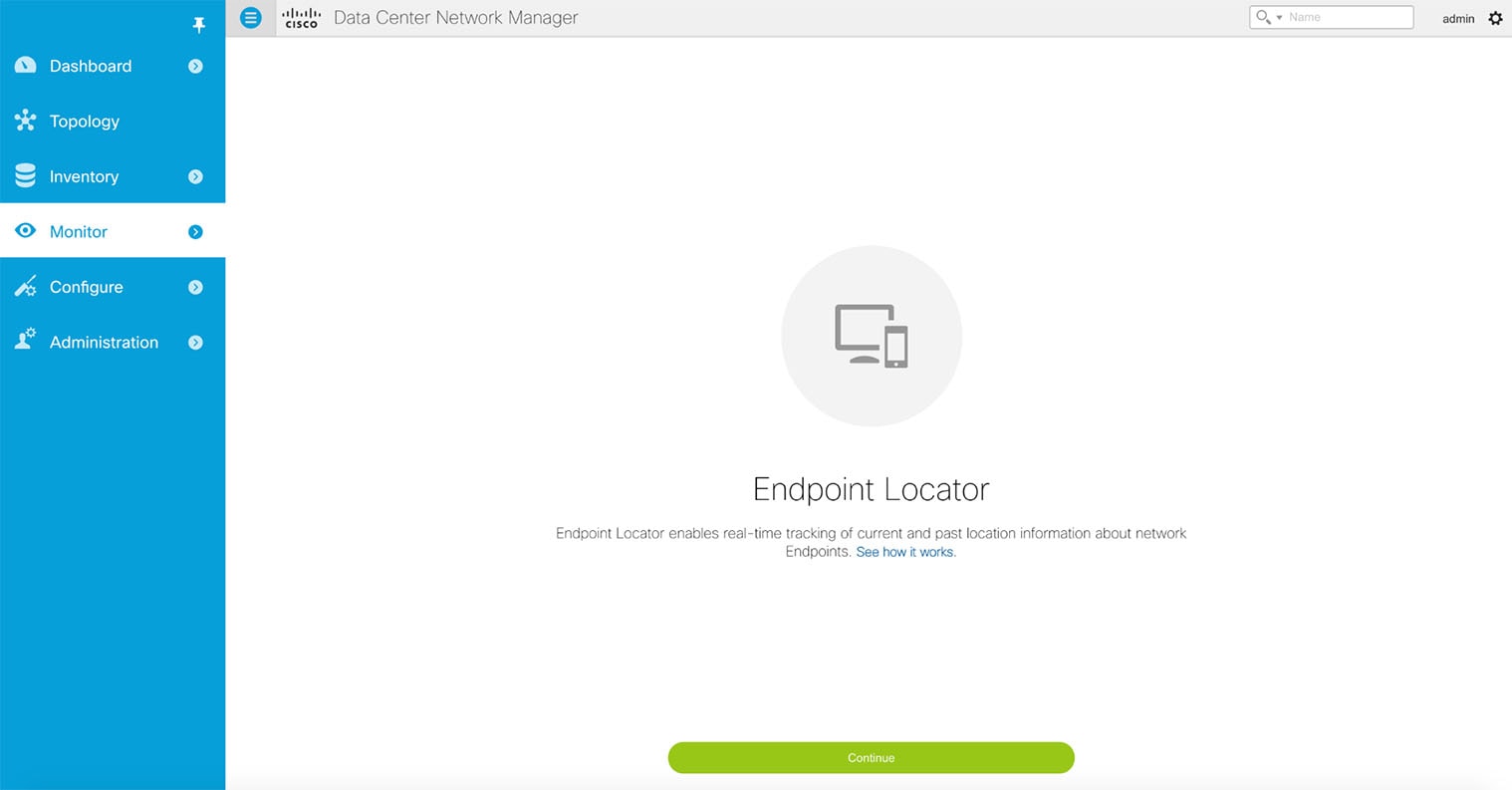
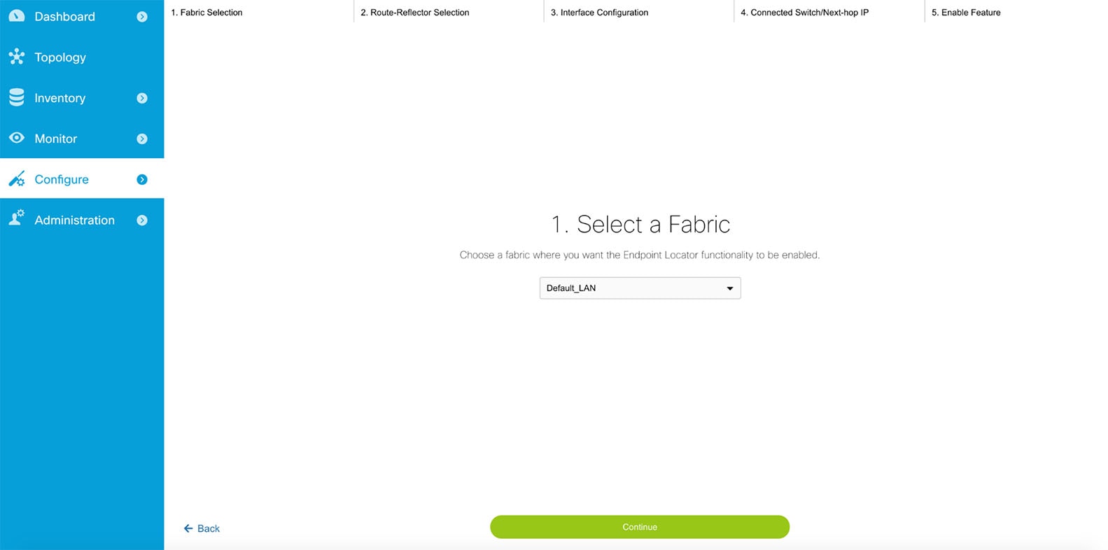
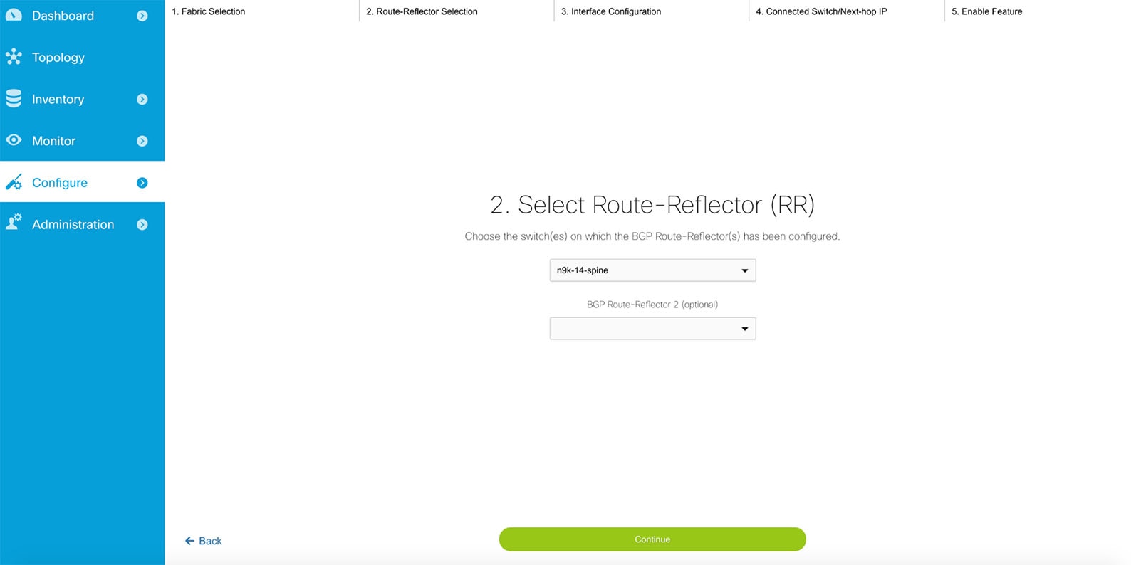
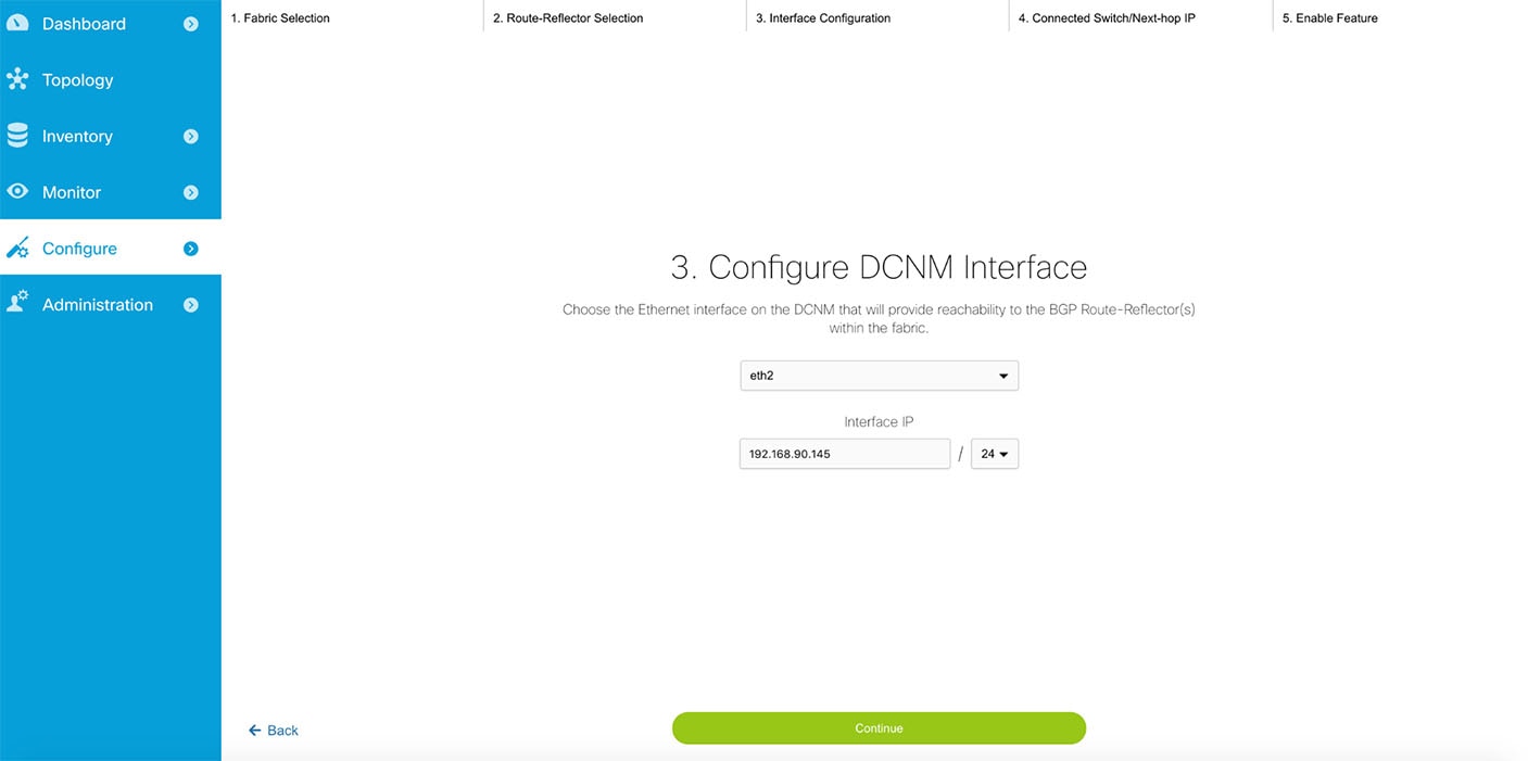
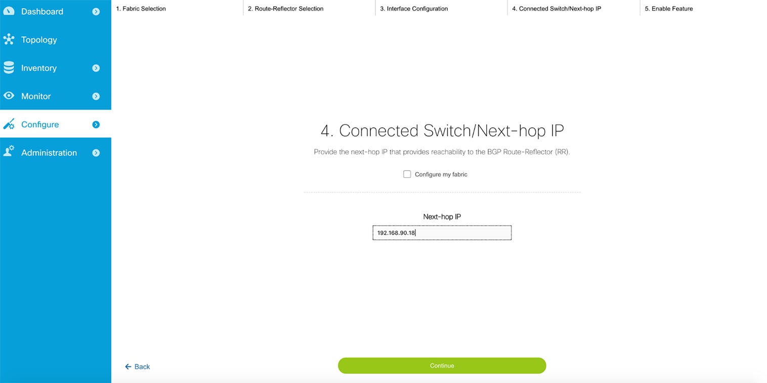
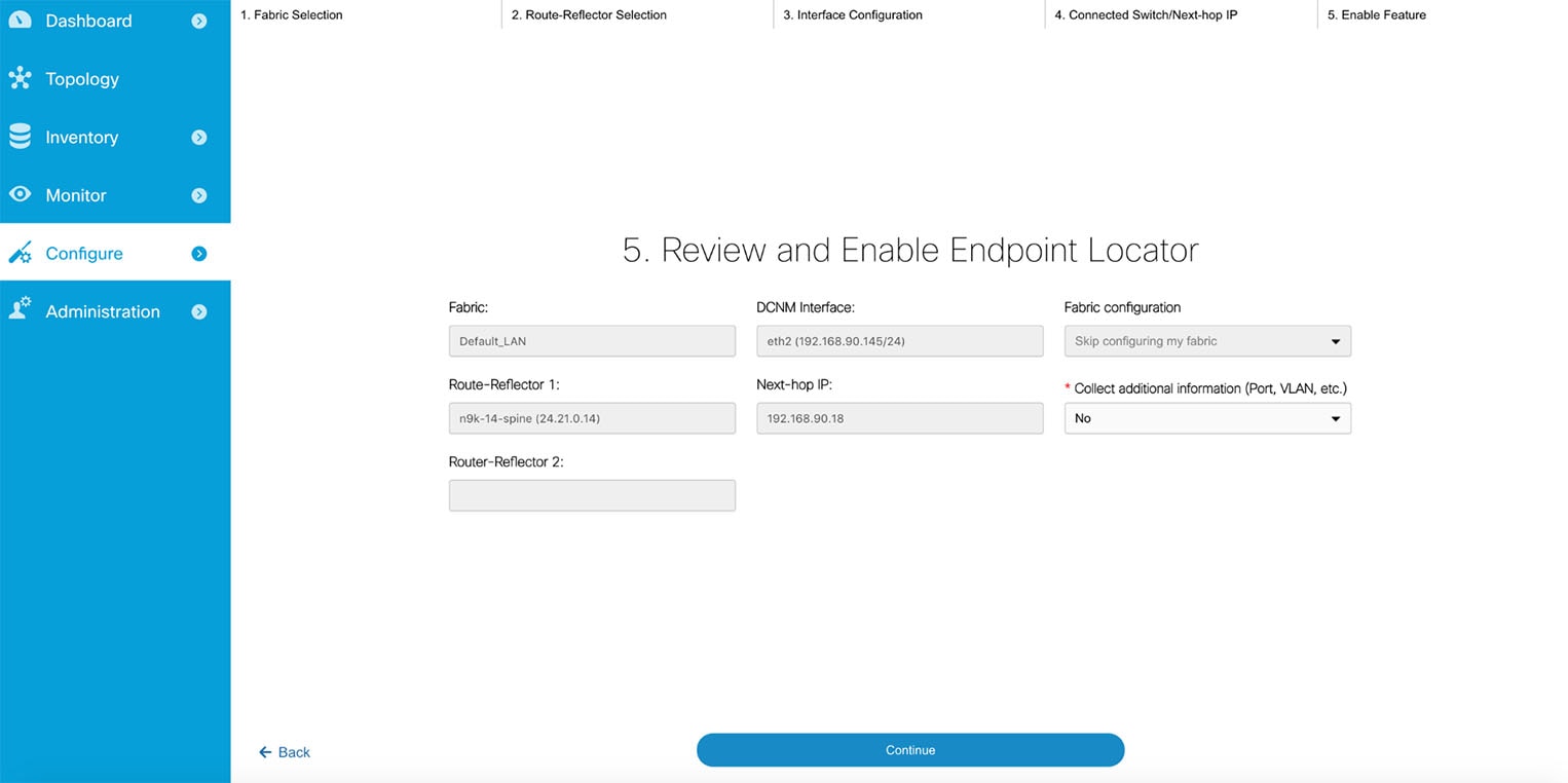
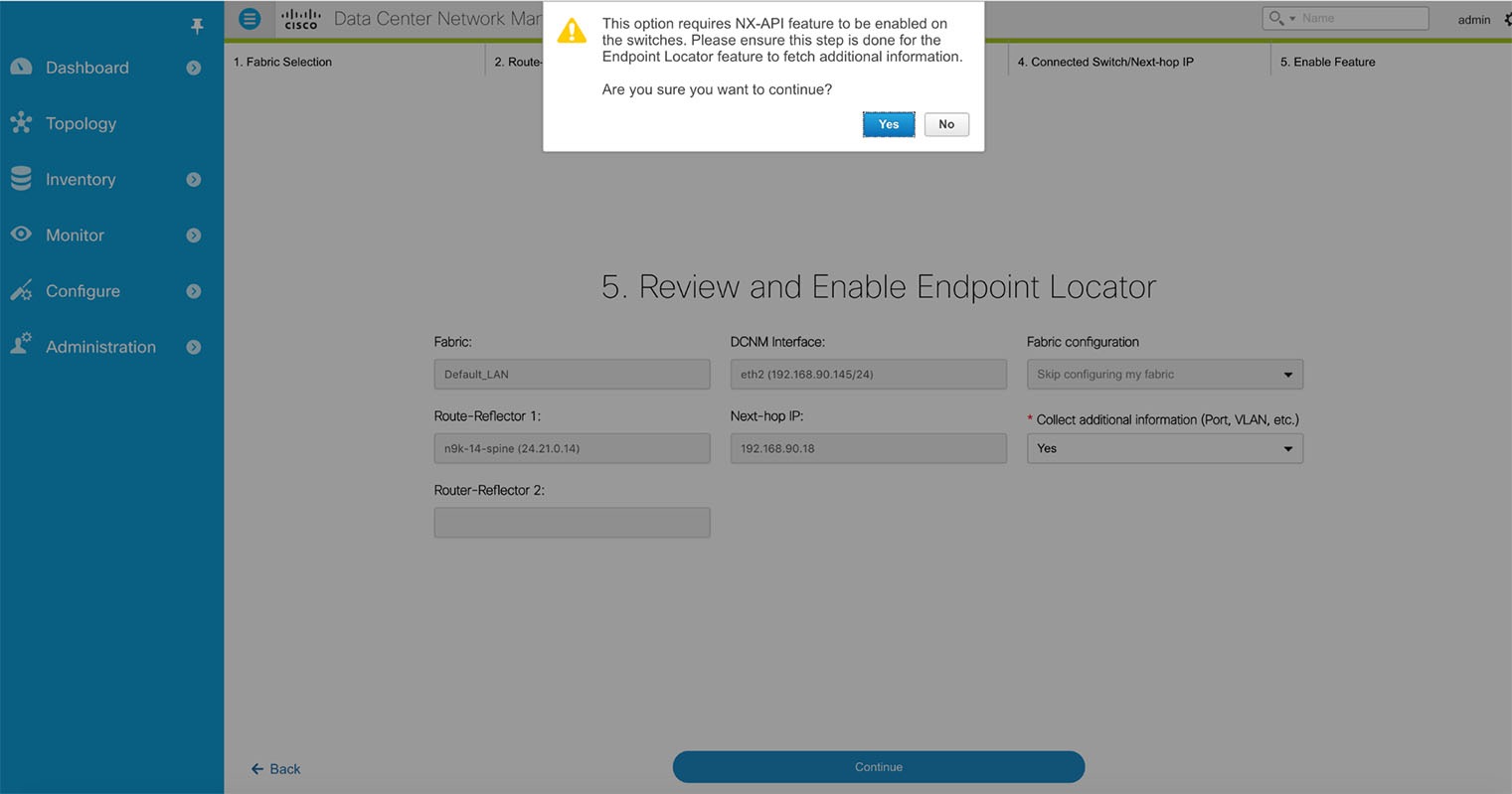
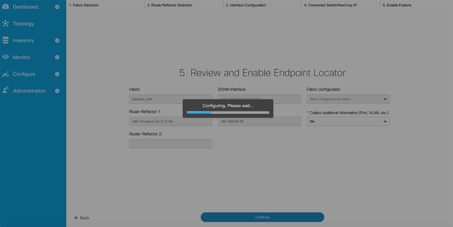
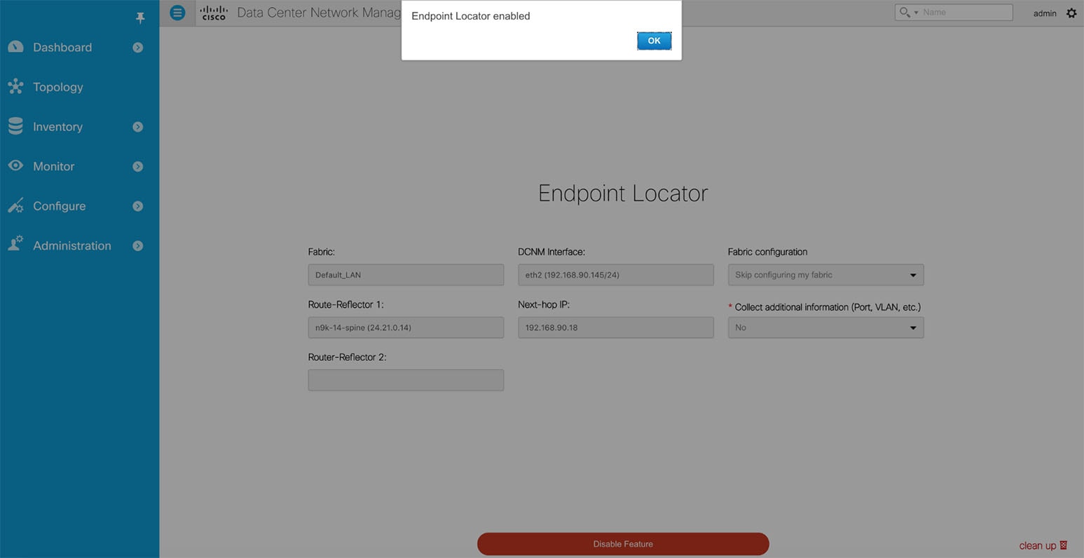
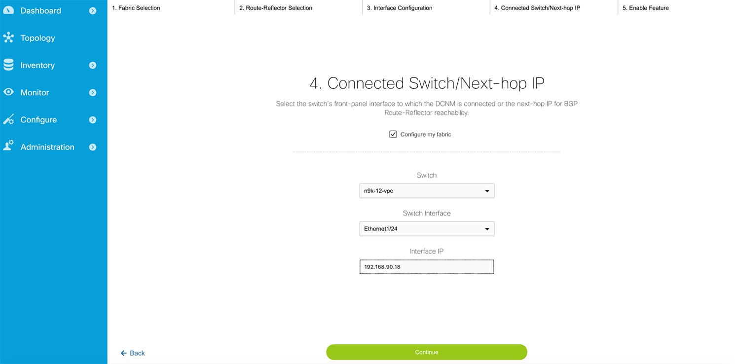
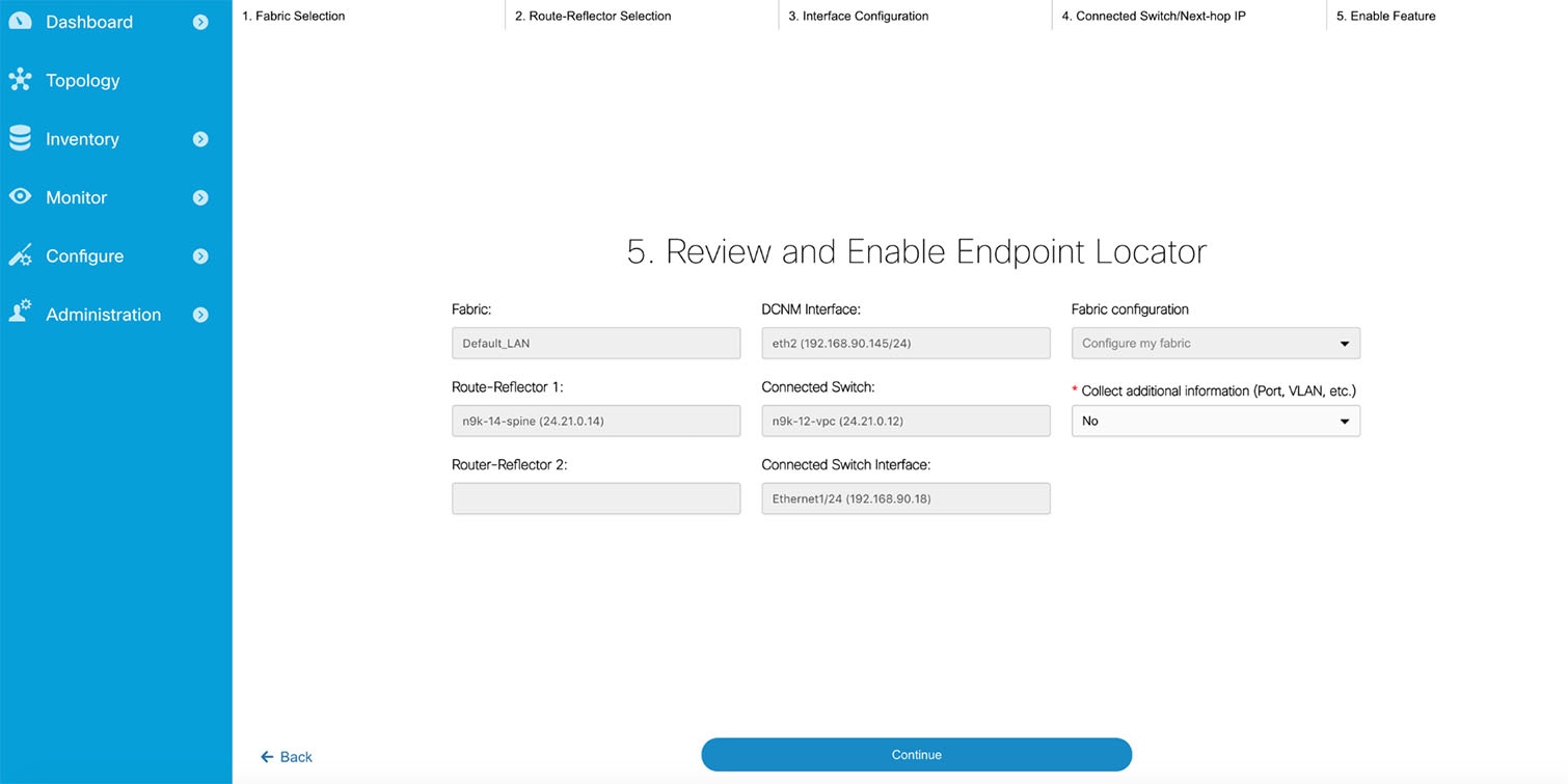
Flushing the Endpoint Database
| Step 1 | Choose Configure > Endpoint Locator > Configure, and then click the clean up link.
This shows a warning message indicating that all the endpoint information from the database will be flushed.
|
| Step 2 | Click Delete to continue or Cancel in case the user wants to abort. |
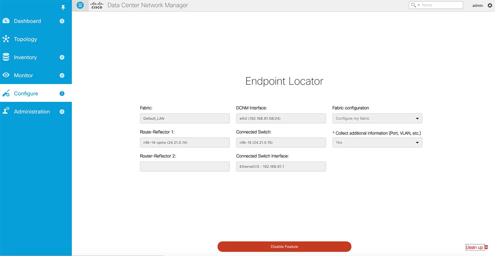
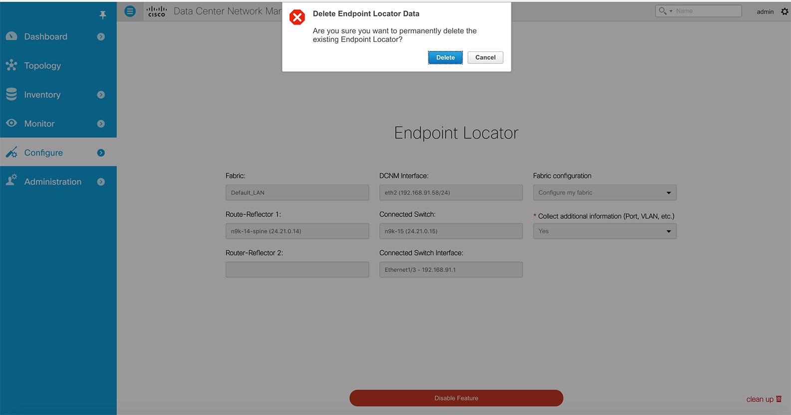
Adding High Availability Node to Endpoint Locator Configuration
| Step 1 | From the menu bar, choose Monitor > Endpoint Locator > Configure. The Endpoint Locator page appears and the fabric configuration details are displayed. |
| Step 2 | Click the Add HA node link. |
| Step 3 | In the Configure Standby DCNM Interface page, choose the Ethernet interface on DCNM that will provide reachability to the BGP Route-Reflector(s) within the fabric. |
| Step 4 | Click Continue. |
| Step 5 | In the Connected Switch on Standby DCNM screen, select the physical switch's front-panel interface to which the DCNM is connected. |
| Step 6 | Click Configure HA Node. The configuration details are displayed on the Endpoint Locator page. |
Configuring Endpoint Locator in DCNM High Availability Mode
| Step 1 | From the menu bar, choose Monitor > Endpoint Locator > Configure. The Endpoint Locator page appears and the fabric configuration details are displayed. |
| Step 2 | In the Select a fabric to configure endpoint locator in DCNM HA mode. |
| Step 3 | Click Continue. |
| Step 4 | Select a Route-Reflector (RR). |
| Step 5 | Click Continue. |
| Step 6 | Configure Ethernet interfaces on both primary and standby DCNM nodes. |
| Step 7 | Click Continue. |
| Step 8 | Select switch interface connected to both primary and standby DCNM. |
| Step 9 | Click Continue. |
| Step 10 | Configure the Connect Switch or Next-hop IP. |
| Step 11 | Click Continue.
After you configure the Endpoint Locator in HA mode, you can view details such as Endpoint Activity and Endpoint History in the Endpoint dashboard. To view these details, navigate to Monitor > Endpoint Locator > Explore. |
Disabling Endpoint Locator
Troubleshooting Endpoint Locator
There may be multiple reasons why enabling the Endpoint Locator feature may fail. Typically, if the appropriate devices are selected and the IP addresses to be used are correctly specified, the connectivity of the DCNM to the BGP RR may not be present due to which the feature cannot be enabled. This is a sanity check that is present to ensure that basic IP connectivity is available. The following image shows an example error scenario that was encountered during an attempt to enable the EPL feature.
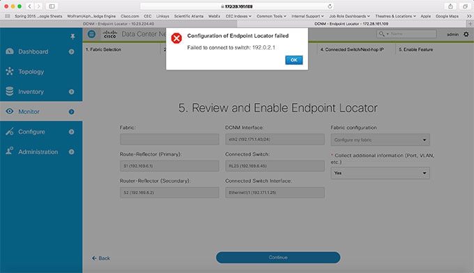
The logs for EPL are located at the following location: /usr/local/cisco/dcm/fm/logs. The log that provides further details on what all occurred when the EPL feature is enabled or disabled, are present in the file epl.log. The following example provides a snapshot of the log that will provide the user further information on when EPL enablement failed.
The following example helps you to understand why Endpoint Locator is unable to Connect to a switch.
#tail -f epl.log
2017.04.08 07:47:05 INFO [epl] Running script: [/sbin/appmgr, status, epls]
2017.04.08 07:47:05 INFO [epl] Received response:
2017.04.08 07:47:05 INFO [epl]
2017.04.08 07:47:05 INFO [epl] >>> Sat Apr 8 07:47:05 PDT 2017
2017.04.08 07:47:05 INFO [epl] appmgr status epls
2017.04.08 07:47:05 INFO [epl]
2017.04.08 07:47:05 INFO [epl] EPLS is stopped...
2017.04.08 07:47:08 INFO [epl] Running command: ifdown eth2
2017.04.08 07:47:08 INFO [epl] Received response:
2017.04.08 07:47:08 INFO [epl] EPL disabled succesfully
2017.04.08 08:00:06 INFO [epl] Enable End Point Locator
2017.04.08 08:00:13 ERROR [epl] Failed to connect to switch 192.169.6.2:java.lang.Exception: Authentication failed : Ssh/Telnet failed to connect with the switch
2017.04.08 08:00:13 INFO [epl] Failed to Enabled End Point Locator. Trying to removing configuration
2017.04.08 08:00:13 INFO [epl] Disable EPL
2017.04.08 08:00:19 ERROR [epl] Failed to connect to switch 192.169.6.2:java.lang.Exception: Authentication failed : Ssh/Telnet failed to connect with the switch
2017.04.08 08:00:19 ERROR [epl] Failed to connect to switch: 192.169.6.2
2017.04.08 08:00:21 ERROR [epl] Failed to unconfigure BGP neighbor or failed to connect to switch or fabric information not provided.
2017.04.08 08:00:21 ERROR [epl] Failed to unconfigure BGP neighbor or failed to connect to switch or fabric information not provided.
2017.04.08 08:00:21 INFO [epl] Received response: configure terminal
Interface Ethernet1/1
no ip address
switchport
end
Enter configuration commands, one per line. End with CNTL/Z.
(config)# Interface Ethernet1/1
(config-if)# no ip address
(config-if)# switchport
(config-if)# end
# from 192.169.6.45
2017.04.08 08:00:21 ERROR [epl] Failed to disable EndPoint locator: java.lang.NullPointerException
2017.04.08 08:00:21 INFO [epl] EPL disabled succesfully
In this example, the LAN credentials set in DCNM for accessing the switch were incorrect. There may be other reasons for which enablement of the EPL feature may fail. In all scenarios, an appropriate error message will be depicted to the user and additional context information can be obtained from epl.log.
Once EPL is successfully enabled, all the debug/error/info logs associated with endpoint information are stored in bgp.log. Depending on the scale of the network and the number of endpoint events, the file size may grow. Hence, there is a restriction on the maximum number and size of bgp.log. Up to 10 such files will be stored with each file having a maximum size of 10MB.
As mentioned earlier, the Endpoint Locator relies on BGP updates to get endpoint information. In order for this to work, the switch loopback or VTEP interface IPs must be discovered on the DCNM for all switches that have endpoints. This can be validated by navigating to the Cisco DCNM Switch Dashboard Interfaces tab, and verifying if the IP/Prefix associated with the corresponding L3 interfaces (typically loopbacks) are correctly displayed.
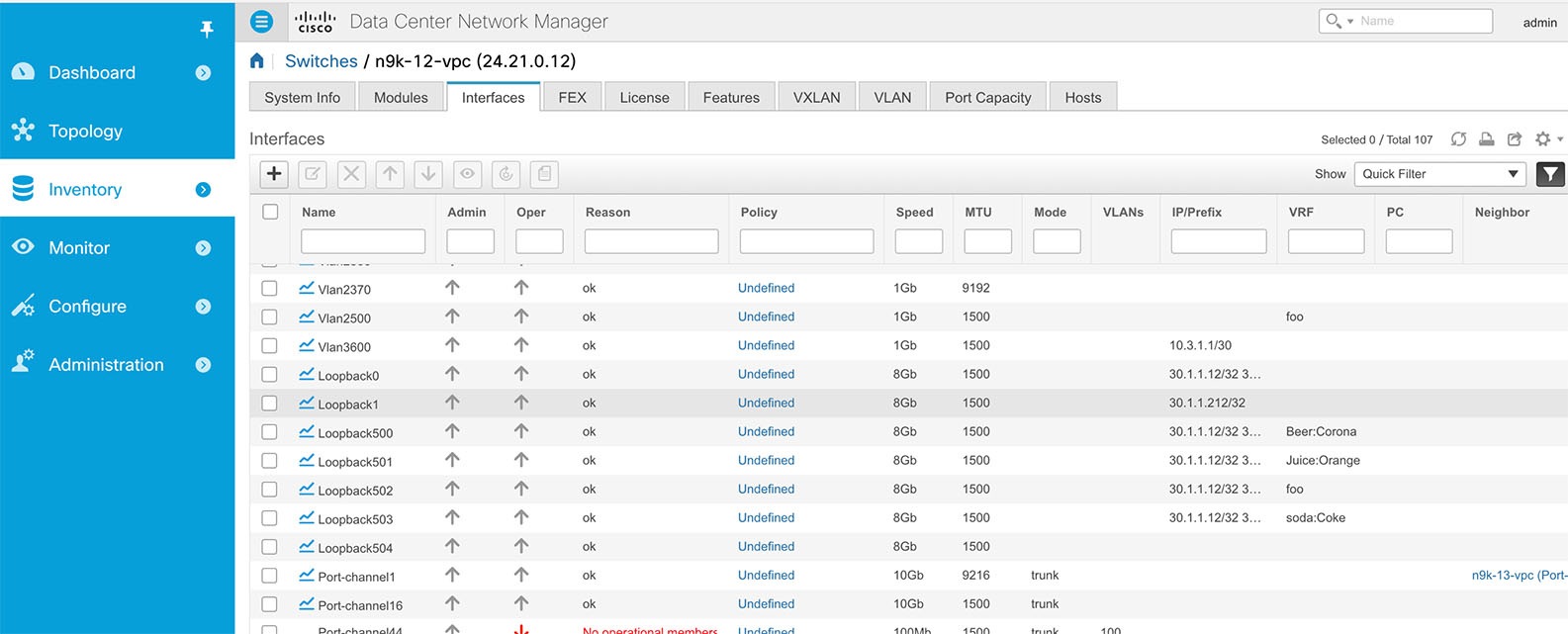
In a large-scale setup, it may take more than 30 seconds (default timer set in Cisco DCNM) to get this information from the switch. If this occurs, the ssh.read-wait-timeout property (in the Administration > DCNM Server > Server Properties page) should be changed from 30000(default) to 60000 or a higher value.
SAN
The SAN menu includes the following submenus:
SAN Zoning
Zoning enables you to set up access control between storage devices or user groups. If you have administrator privileges in your fabric, you can create zones to increase network security and to prevent data loss or corruption. Zoning is enforced by examining the source-destination ID field.
The following table describes the fields and icons that appear on Cisco DCNM Configure > SAN > Zoning tab.
|
Field |
Description |
|---|---|
|
Fabric |
From the Fabric drop-down list, you can choose the fabric for which you are configuring or viewing the SAN Zoning. |
|
VSAN |
From the VSAN drop-down list, you can choose the VSAN for which you are configuring zoning. |
|
Switches |
From the Switch drop-down list, select the switch to which you want to configure. |
|
Commit Changes |
Commits the Zoning configuration changes to all the switches. This field is only applicable when a zone is in the enhanced or smart mode. |
|
Distribute |
Distributes the Zoning configuration to all the switches. This field is only applicable when a zone is in the basic mode. |
|
Export All |
You can export the Zoning configurations to a .csv file, and save it on your local directory. |
|
Zonesets |
Lists all the Zoneset configured for the selected Fabric, VSAN and the Switch. |
|
Zones |
Lists all the Zones configured under the selected Zoneset. |
|
Zone Members |
Lists the members present in the selected Zone. |
|
Available to Add |
Lists the available devices to add to the Zones. |
|
Clear Server Cache |
Clears the cache on the Cisco DCNM server. |
|
Discard Pending Changes |
Discards the changes in progress. |
This section contains the following:
Zonesets
Based on the selected Fabric, VSAN and Switch, the Zoneset area displays the configured zonesets and their status. You can create, copy, delete or edit the zonesets. Further, the zonesets can be activated or deactivated.
| Step 1 | To create zonesets, from Cisco DCNM
Web Client >
Configure > SAN Zoning > Zonesets, click Create Zoneset
icon. |
| Step 2 | To clone or copy zonesets, from Cisco DCNM
Web Client >
Configure > SAN Zoning > Zonesets, select the zone radio
button and click Clone\Copy Zoneset icon.
The Clone or Copy Zoneset window shows two options. |
| Step 3 | To delete the zoneset, from Cisco DCNM
Web Client >
Configure > SAN Zoning > Zones, select the zoneset radio
button and click delete zoneset icon.
A confirmation window appears. Click Yes to delete the zoneset. |
| Step 4 | To edit the zone name, from Cisco DCNM
Web Client >
Configure > SAN Zoning > Zoneset, select the zone radio
button and click Rename Zoneset icon.
In the Name field, enter the new name for the zoneset. Click Rename. |
| Step 5 | To Activate Zoneset, from Cisco DCNM
Web Client
> Configure > SAN Zoning > Zonesets, select the zoneset
radio button and click Activate.
The Zoneset Differences window shows the changes made to the zoneset since it was activated previously. Click Activate. |
| Step 6 | To Deactivate Zoneset, from Cisco DCNM
Web Client >
Configure > SAN Zoning > Zonesets, select the zoneset
radio button and click Deactivate.
A confirmation window appears. Click Yes to deactivate the zoneset. |
Zones
Based on the Zoneset selected, the zones configured under that zoneset are displayed in the Zones area. It will also display true or false only when the VSAN has smart zone enabled. You can create, copy, delete or edit the zones. Furthermore, the zones can be added to or removed from the selected Zoneset. You can also enable or disable smart zone on the zone table.
Note | You must select the Zoneset for which you need to alter the zones. Select Zoneset radio button in the Zonesets area. The zones configured on the selected Zoneset and zones on the switch are displayed. The zones that are a part of the Zone are marked with a green check mark. |
The Zones area has the following fields and their descriptions.
|
Field |
Description |
|---|---|
|
In Zoneset |
Specifies whether a zone is part of a zoneset. Displays true if the zone is part of a zoneset. Otherwise, displays false. You can search by choosing true or false from the In Zoneset drop-down list. |
|
Zone Name |
Displays the name of the zone. You can search by specifying the zone name. |
|
Smart Zone |
Specifies whether a zone is a smart zone. Displays true if the zone is a smart zone. Otherwise, displays false. You can search this field by choosing true or false from the Smart Zone drop-down list. This field only shows up when the VSAN has smart zone enabled. |
| Step 1 | To create zones,
from Cisco DCNM
Web
Client > Configure > SAN > Zoning > Zones, click Create
icon.
| ||
| Step 2 | To Clone Zones,
from Cisco DCNM
Web
Client > Configure > SAN > Zoning > Zones, select the
zone radio button and click Clone Zone icon.
The Clone Zone screen appears. | ||
| Step 3 | To add zone to a
zoneset, from Cisco DCNM
Web
Client > Configure > SAN Zoning > Zones, select the zone
that is not a part of the zoneset and click Add Zone icon. You can select more
than one zone to be added to the Zoneset.
The zone will be added to the selected Zoneset. A green tick mark appears next to the Zone name to indicate that the zone is added to the zoneset. | ||
| Step 4 | To remove zone from a zoneset, from Cisco DCNM Web Client > Configure > SAN Zoning > Zones, check the zone check box and click Remove Zone icon. You can select more than one Zone to be deleted from the Zoneset.
The zone will be removed from the selected Zoneset. A green tick mark disappears next to the Zone name to indicate that the zone is removed from the zoneset. | ||
| Step 5 | To Delete Zones, from Cisco DCNM Web Client > Configure > SAN Zoning > Zones, check zone check box and click Delete Zone icon.
A confirmation window appears. Click Yes to delete the selected zones.
| ||
| Step 6 | To edit the zone
name, from Cisco DCNM
Web
Client > Configure > SAN Zoning > Zones, select the zone
radio button and click Rename Zone icon.
In the Name field, enter the new name for the zone. Click Rename. | ||
| Step 7 | To enable smart zone, from Cisco DCNM
Web Client > Configure > SAN Zoning >
Zones, select the zone radio button and click
Enable Smart Zone icon.
Under the Smart Zone column, it will display True. | ||
| Step 8 | To disable smart zone, from Cisco DCNM
Web Client > Configure > SAN Zoning >
Zones, select the zone radio button and click
Disable Smart Zone icon.
Under the Smart Zone column, it will display false. |
Zone Members
Based on the selected Zoneset and the Zone, the Zone Members area displays the zone members and their status. You can create, or remove members from the Zoneset.
The Zone Members area has the following fields and their descriptions.
|
Field |
Description |
|---|---|
|
Zone |
Displays the Zone under which this member is present. You can search by zone name in this field. |
|
Zoned By |
Displays the type of zoning. You can search by type of zoning such as WWN, FCID, fcAlias, or iSCSI. |
|
Device Type |
Displays the smart zoning device type. The applicable values are Host, Storage, or Both. You can search this field by choosing Host, Storage or Both from the Device Type drop-down list. This field only shows up when the VSAN has smart zone enabled. |
|
Name |
Displays the name of the zone member. You can search by specifying the zone name. |
|
Switch Interface |
Specifies the switch interface that the zone member is attached to. You can search by specifying the switch interface. |
|
FcId |
Specifies the FcID associated with the zone member. You can search by specifying the FcID associated with the zone member. |
|
WWN |
Specifies the WWN of the switch. You can search by specifying the WWN of the switch. |
| Step 1 | To create zone
members, from Cisco DCNM
Web
Client > Configure > SAN Zoning > Zone Members, click
Create icon.
The Create and Add feature allows you to add a member to a zone that does not exist in the fabric, currently. This feature can also be utilized when the device discovery did not discover all the devices. With the Available to add feature, you can add a discovered device to the zone. |
| Step 2 | To Remove Zone
Member, from Cisco DCNM
Web
Client > Configure > SAN Zoning > Zone Members, check the
zone member check box and click Remove Member icon.
You can more than one zone member at a time, for deletion. |
Available to Add
Perform the following task to add discovered devices to the zone(s).
The Available to Add area has the following fields and their descriptions.
|
Field |
Description |
|---|---|
|
Type |
Displays the smart zoning device type. The applicable values are Host or Storage. You can search this field by choosing Hostor Storage from the Type drop-down list. |
|
Name |
Displays the name of the zone. You can search by specifying the zone name. |
|
Switch Interface |
Specifies the switch interface that the zone member is attached to. You can search by specifying the switch interface. |
|
FcId |
Specifies the FcID associated with the zone member. You can search by specifying the FcID associated with the zone member. |
|
WWN |
Specifies the WWN of the switch. You can search by specifying the WWN of the switch. |
| Step 1 | From Cisco DCNM Web Client > Configure
> SAN > Zoning > Available to Add, in the Zone by area
select the Ports or Device radio buttons.
The Zone by feature determines if the device must be added to the zone using the device WWN or Device alias. A window appears showing the list of End Ports or Devices available to add. If you choose Zone By: End Port, the devices are added to the zones by WWN. If you choose Zone By: Device Alias, the devices are added to the zones by Device Alias. Based on the zone by option you choose, the devices are displayed. | ||
| Step 2 | Select the devices to add to a zone. | ||
| Step 3 | Click Add to add the
selected devices to the zone.
|
Configuring FCIP
Cisco DCNM allows you to create FCIP links between Gigabit Ethernet ports, enables Fibre Channel write acceleration and IP compression. You can configure FCIP from Cisco DCNM Web Client > SAN > FCIP.
| Step 1 | From the menu bar, select Configure > SAN > FCIP.
The Welcome page displays the tasks to configure FCIP using the FCIP Wizard. | ||
| Step 2 | Click Next to select the switch pair. | ||
| Step 3 | Select two MDS switches to be connected via FCIP for Between Switch and and Switch from the drop-down list.
Each switch must have an ethernet port connected to an IP network to function correctly.
| ||
| Step 4 | Click Next to select the Ethernet ports. | ||
| Step 5 | Select the Ethernet ports to be used in FCIP ISL between the selected switches.
Down ports should be enabled to function correctly. Security can be enforced for unconfigured 14+2, 18+4, 9250i and SSN16 Ethernet ports. | ||
| Step 6 | Click Next to specify the IP addresses and add IP route. | ||
| Step 7 | Enter the Ethernet ports IP addresses and specify the IP Routes if the port addresses are in a different subnet.
| ||
| Step 8 | Click Next to specify Tunnel properties. | ||
| Step 9 | Specify the following parameters to tunnel the TCP connections.
Enter the parameters
| ||
| Step 10 | Click Next to create FCIP ISL. | ||
| Step 11 | Enter the Profile ID and Tunnel ID for the switch pair, and select the FICON Port Address from the drop-down list. Click View Configured to display the Profiles and Tunnels information. Select the Trunk Mode from nonTrunk, trunk and auto. Specify the Port VSAN for nonTrunk and auto, and allowed VSAN List for Trunk tunnel. | ||
| Step 12 | Click Next to the last summary page.
The Summary view displays what you have selected in the previous steps. | ||
| Step 13 | Click Deploy to configure FCIP or click Finish complete the configuration and deploy later. |
Device Alias
A device alias is a user-friendly name for a port WWN. Device alias name can be specified when configuring features such as zoning, QoS and port security. The device alias application uses the Cisco Fabric Services (CFS) infrastructure to enable efficient database management and fabric-wide distribution.
This section contains context sensitive online help content under Configure > SAN > Device Alias.
The following table describes the fields that appear on Cisco DCNM Web Client Configure > SAN > Device Alias.
|
Field |
Description |
|---|---|
|
Seed Switch |
Displays the device alias seed switch name. |
|
Device Alias |
Displays the alias retrieved from the seed switch. |
|
pWWN |
Displays the port WWN. |
This section contains the following:
Configuration
Select the Fabric from the Fabric drop-down list. The list of device aliases existing on the fabric will be retrieved and displayed.
Before performing any Device Alias configuration, check the status on the CFS tab, to ensure that the status is "success".
Note | To perform Device Alias configuration from the Cisco DCNM Web client, the fabric must be configured as Device Alias enhanced mode. |
| Step 1 | To delete the device alias, Cisco DCNM Web Client > Configure > SAN > Device Alias > Configuration tab, check the device alias you need to delete. | ||
| Step 2 | To create the device alias, from Cisco DCNM Web Client > Configure > SAN > Device Alias > Configuration tab, click Create.
The Add Device Alias windows appears. All the provisioned port WWNs are populated in the table.
You can also create a device alias with a non-provisioned port WWN.
| ||
| Step 3 | For end devices with an attached service profile, the service profile name is populated to the Device Alias field. This allows the service profile name as device alias name for those devices. |
Device Alias creation is CFS auto-committed after clicking Apply. Click CFS tab to check if CFS is properly performed after the device alias was created. In case of failure, you must troubleshoot and fix the problem.
CFS
Select the Fabric from the Fabric drop-down list. The list of device aliases existing on the fabric will be retrieved and displayed.
CFS information is listed for all the eligible switches in the fabric. Before performing any Device Alias configuration, check the status on the CFS tab, to ensure that the status is "success". If the CFS is locked by another user, or if the previous operation failed, ensure that the CFS session is unlocked.
The Cisco DCNM Web Client Configure > SAN > Device Alias > CFS tab shows the following fields.
| Step 1 | To commit the CFS configuration, from Cisco
DCNM Web Client >
Configure > SAN > Device Alias > CFS tab, click the Switch radio
button.
Click Commit. The CFS configuration for this switch is committed. |
| Step 2 | To abort the CFS configuration, from Cisco
DCNM Web Client >
Configure > SAN > Device Alias > CFS tab, click the Switch radio
button.
Click Abort. The CFS configuration for this switch will be aborted. |
| Step 3 | To clear the lock on the CFS configuration of
the switch, from Cisco DCNM Web Client > Configure > SAN > Device Alias > CFS
tab, click the Switch radio button.
Click Clear Lock. If the CFS is locked by another user, or if the previous operation failed, ensure that the CFS session is unlocked. |
Port Monitoring
This feature allows you to save custom Port Monitoring policies in the Cisco DCNM database. It allows you to push the selected custom policy to one or more fabrics or Cisco MDS 9000 Series Switches. The policy is designated as active Port-Monitor policy in the switch.
This feature is supported only on the Cisco MDS 9000 SAN Switches and therefore the Cisco DCNM user is allowed to select the MDS switch to push the policy.
Cisco DCNM provides five templates to customize the policy. The user-defined policies are saved in the Cisco DCNM database. You can select any template or customized policy to push to the selected fabric or switch with the desired port type.
Note | You can edit only user-defined policies. |
The following table describes the fields that appear on Cisco DCNM Web Client > Configure > SAN > Port Monitoring.
|
Field |
Description |
||
|---|---|---|---|
|
Templates |
This drop-down list shows the following templates for policies:
|
||
|
Save |
Allows you to save your changes for the user-defined policies. |
||
|
Save As |
Allows you to save an existing policy as a new policy with a different name. This creates another item in the templates as Custom Policy. The customized policy will be saved under this category. If you click Save As while the policy is edited, the customized policy will be saved.
|
||
|
Delete |
Allows you to delete any user-defined policies. |
||
|
Push to switches |
Allows you to select a fabric or switch and push the selected policies with a desired port type. The available port types are:
The following policies select the trunks/Core policy type:
The following policies select the access-port/Edge policy type:
The following policies select the all policy type:
Select the parameters and click Push to push the policies to the switches in the fabric. If there is any active policy with the same or common port type, the push command will configure the same policy on the selected devices. This policy will replace the existing active policy with the same or common port type. If you click Push to Switches while the policy is edited, the customized policy will not be saved. |
||
|
Counter Description |
Specifies the counter type. Move the pointer to the "i" icon next to the counter description to view detailed information. |
||
|
Rising Threshold |
Specifies the upper threshold limit for the counter type. |
||
|
Rising Event |
Specifies the type of event to be generated when rising threshold is reached or crossed. |
||
|
Falling Threshold |
Specifies the lower threshold limit for the counter type. |
||
|
Falling Event |
Specifies the type of event to be generated when falling threshold is reached or crossed. |
||
|
Poll Interval |
Specifies the time interval to poll for the counter value. |
||
|
Warning Threshold |
Allows you to set an optional threshold value lower than the rising threshold value and higher than the falling threshold value to generate syslogs. The range is 0–9223372036854775807. |
||
|
Port Guard |
Specifies if the port guard is enabled or disabled. The value can be false, flap, or errordisable. The default value is "false". |
||
|
Monitor ? |
The default value is "true". |
 Feedback