System Management Configuration Guide, Cisco DCNM for LAN, Release 7.x
Bias-Free Language
The documentation set for this product strives to use bias-free language. For the purposes of this documentation set, bias-free is defined as language that does not imply discrimination based on age, disability, gender, racial identity, ethnic identity, sexual orientation, socioeconomic status, and intersectionality. Exceptions may be present in the documentation due to language that is hardcoded in the user interfaces of the product software, language used based on RFP documentation, or language that is used by a referenced third-party product. Learn more about how Cisco is using Inclusive Language.
- Updated:
- May 13, 2015
Chapter: Configuring SPAN
Configuring SPAN
This chapter describes how to configure an Ethernet Switched Port Analyzer (SPAN) to analyze traffic between ports on Cisco NX-OS devices.
You can configure an Ethernet switched port analyzer (SPAN) to monitor traffic in and out of your device.

Note![]() System-message logging levels for the SPAN feature must meet or exceed Cisco DCNM requirements. During device discovery, Cisco DCNM detects inadequate logging levels and raises them to the minimum requirements. Cisco Nexus 7000 Series switches that run Cisco NX-OS Release 4.0 are an exception. For Cisco NX-OS Release 4.0, prior to device discovery, use the command-line interface to configure logging levels to meet or exceed Cisco DCNM requirements. For more information, see the Fundamentals Configuration Guide, Cisco DCNM for LAN, Release 5.x
System-message logging levels for the SPAN feature must meet or exceed Cisco DCNM requirements. During device discovery, Cisco DCNM detects inadequate logging levels and raises them to the minimum requirements. Cisco Nexus 7000 Series switches that run Cisco NX-OS Release 4.0 are an exception. For Cisco NX-OS Release 4.0, prior to device discovery, use the command-line interface to configure logging levels to meet or exceed Cisco DCNM requirements. For more information, see the Fundamentals Configuration Guide, Cisco DCNM for LAN, Release 5.x
Note![]() The Cisco NX-OS release that is running on a managed device may not support all the features or settings described in this chaptersection. For the latest feature information and caveats, see the documentation and release notes for your platform and software release.
The Cisco NX-OS release that is running on a managed device may not support all the features or settings described in this chaptersection. For the latest feature information and caveats, see the documentation and release notes for your platform and software release.
Information About SPAN
SPAN analyzes all traffic between source ports by directing the SPAN session traffic to a destination port with an external analyzer attached to it.
You can define the sources and destinations to monitor in SPAN sessions on the local device.
This section includes the following topics:
- SPAN Sources
- SPAN Destinations
- SPAN Sessions
- Virtual SPAN Sessions
- Multiple SPAN Sessions
- High Availability
- Virtualization Support
SPAN Sources
The interfaces from which traffic can be monitored are called SPAN sources. Sources designate the traffic to monitor and whether to copy ingress, egress, or both directions of traffic. SPAN sources include the following:
SPAN Destinations
SPAN destinations refer to the interfaces that monitor source ports. Destination ports receive the copied traffic from SPAN sources.
SPAN Sessions
You can create SPAN sessions designating sources and destinations to monitor.
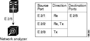
Figure 8-1 shows a SPAN configuration. Packets on three Ethernet ports are copied to destination port Ethernet 2/5. Only traffic in the direction specified is copied.
Virtual SPAN Sessions
You can create a virtual SPAN session to monitor multiple VLAN sources and choose only VLANs of interest to transmit on multiple destination ports. For example, you can configure SPAN on a trunk port and monitor traffic from different VLANs on different destination ports.
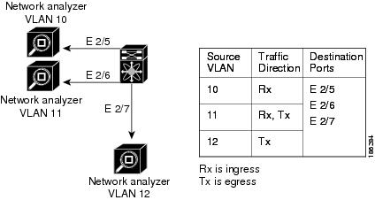
Figure 8-2 shows a virtual SPAN configuration. The virtual SPAN session copies traffic from the three VLANs to the three specified destination ports. You can choose which VLANs to allow on each destination port to limit the traffic that the device transmits on it. In Figure 8-2, the device transmits packets from one VLAN at each destination port.
Note![]() Virtual SPAN sessions cause all source packets to be copied to all destinations, whether the packets are required at the destination or not. VLAN traffic filtering occurs at the egress destination port level.
Virtual SPAN sessions cause all source packets to be copied to all destinations, whether the packets are required at the destination or not. VLAN traffic filtering occurs at the egress destination port level.
Figure 8-2 Virtual SPAN Configuration
For information about configuring a virtual SPAN session, see the “Configuring a Virtual SPAN Session” section.
Multiple SPAN Sessions
You can define multiple SPAN sessions. You can shut down an unused SPAN session.
For information about shutting down SPAN sessions, see the “Shutting Down or Resuming a SPAN Session” section.
High Availability
The SPAN feature supports stateless and stateful restarts. After a reboot or supervisor switchover, applies the running configuration.
Virtualization Support
A virtual device context (VDC) is a logical representation of a set of system resources. SPAN applies only to the VDC where the commands are entered.
For information about configuring VDCs, see the Cisco Nexus 7000 Series NX-OS Virtual Device Context Configuration Guide, Release 5.x.
For information about configuring VDCs, see the Virtual Device Context Configuration Guide, Cisco DCNM for LAN, Release 6.x.
Licensing Requirements for SPAN
The following table shows the licensing requirements for this feature:
Prerequisites
The SPAN feature has the following prerequisite (for a full list of feature-specific prerequisites, see the platform-specific documentation):
- System-message logging levels for the SPAN feature must meet or exceed Cisco DCNM requirements. During device discovery, Cisco DCNM detects inadequate logging levels and raises them to the minimum requirements. Cisco Nexus 7000 Series switches that run Cisco NX-OS Release 4.0 are an exception. For Cisco NX-OS Release 4.0, prior to device discovery, use the command-line interface to configure logging levels to meet or exceed Cisco DCNM requirements. For more information, see the Fundamentals Configuration Guide, Cisco DCNM for LAN, Release 5.x .
Guidelines and Limitations
SPAN has the following configuration guidelines and limitations:
- Table 1 lists the SPAN session configuration limits.
|
|
|
|---|---|
- Although you can define up to 18 SPAN sessions, only two SPAN sessions can be running simultaneously.
- An RSPAN VLAN can only be used as a SPAN source. It cannot be used as a SPAN destination.
- Destinations for a SPAN session include Ethernet ports or port-channel interfaces in either access or trunk mode.
- A destination port can be configured in only one SPAN session at a time.
- Destination ports do not participate in any spanning tree instance. SPAN output includes Bridge Protocol Data Unit (BPDU) Spanning-Tree Protocol hello packets.
- You can configure SPAN destinations to inject packets to disrupt a certain TCP packet stream in support of the Intrusion Detection System (IDS).
- You can configure SPAN destinations to enable a forwarding engine to learn the MAC address of the IDS.
- You cannot configure a port as both a source and destination port.
- A single SPAN session can include mixed sources in any combination of the following:
–![]() The inband interface to the control plane CPU
The inband interface to the control plane CPU
–![]() All packets that arrive on the supervisor hardware (ingress)
All packets that arrive on the supervisor hardware (ingress)
–![]() All packets generated by the supervisor hardware (egress)
All packets generated by the supervisor hardware (egress)
- When a SPAN session contains multiple egress source ports, packets that these ports receive may be replicated even though they are not transmitted on the ports. Some examples of this behavior on source ports are as follows:
–![]() Traffic that results from flooding
Traffic that results from flooding
–![]() Broadcast and multicast traffic
Broadcast and multicast traffic
- For VLAN SPAN sessions with both ingress and egress configured, two packets (one from ingress and one from egress) are forwarded from the destination port if the packets get switched on the same VLAN.
- VLAN SPAN monitors only the traffic that leaves or enters Layer 2 ports in the VLAN.
- You can monitor the inband interface only from the default VDC. Inband traffic from all VDCs is monitored.
- You can configure a SPAN session on the local device only.
- If you configure a SPAN session to monitor a routed interface, only the received traffic is captured, even if the session is configured for both directions. This limitation is only for traffic that enters a Layer 2 interface (with SVI as a Layer 3 interface) and then exits a routed (physical Layer 3) interface, which is the source of the monitor session. If traffic enters a routed (physical Layer 3) interface and exits another routed (physical Layer 3) interface, which is the source of the monitor session, then the destination port of the monitor session captures traffic in both directions. A SPAN session captures traffic in both directions if traffic entering the routed port is destined to an IP address (SVI) on the switch.
Platform Support
The following platform supports this feature. For platform-specific information, including guidelines and limitations, system defaults, and configuration limits, see the corresponding documentation.
|
|
|
|---|---|
Default Settings
Table 8-2 lists the default settings for SPAN parameters.
|
|
|
|---|---|
Configuring SPAN
This section includes the following topics:
- Configuring a SPAN Session
- Configuring a Virtual SPAN Session
- Configuring an RSPAN VLAN
- Shutting Down or Resuming a SPAN Session
Note![]() Cisco NX-OS commands for this feature may differ from those in Cisco IOS.
Cisco NX-OS commands for this feature may differ from those in Cisco IOS.
Configuring a SPAN Session
You can configure a SPAN session on the local device only.
For sources, you can specify Ethernet ports, port channels, the supervisor inband interface, VLANs, and RSPAN VLANs. You can specify private VLANs (primary, isolated, and community) in SPAN sources.
A single SPAN session can include mixed sources in any combination of Ethernet ports, VLANs, or the inband interface to the control plane CPU.
When you specify the supervisor inband interface for a SPAN source, the device monitors all packets that arrive on the supervisor hardware (ingress) and all packets generated by the supervisor hardware (egress).
For destination ports, you can specify Ethernet ports or port channels in either access or trunk mode. You must enable monitor mode on all destination ports.
BEFORE YOU BEGIN
You must have already configured the destination ports in access or trunk mode. For more information, see the Cisco Nexus 7000 Series NX-OS Interfaces Configuration Guide, Release 5.x Interfaces Configuration Guide, Cisco DCNM for LAN, Release 6.x.
SUMMARY STEPS
2.![]() interface ethernet slot / port [ -port ]
interface ethernet slot / port [ -port ]
4.![]() switchport mode [access | trunk | private-vlan]
switchport mode [access | trunk | private-vlan]
5.![]() switchport monitor [ingress [learning]]
switchport monitor [ingress [learning]]
6.![]() Repeat Steps 2 and 3 to configure monitoring on additional SPAN destinations.
Repeat Steps 2 and 3 to configure monitoring on additional SPAN destinations.
7.![]() no monitor session session-number
no monitor session session-number
8.![]() monitor session session-number
monitor session session-number
10.![]() source { interface type | vlan { number | range } [ rx | tx | both ]
source { interface type | vlan { number | range } [ rx | tx | both ]
11.![]() Repeat Step 8 to configure all SPAN sources.
Repeat Step 8 to configure all SPAN sources.
12.![]() filter vlan { number | range }
filter vlan { number | range }
13.![]() Repeat Step 10 to configure all source VLANs to filter.
Repeat Step 10 to configure all source VLANs to filter.
14.![]() destination interface type { number | range }
destination interface type { number | range }
15.![]() Repeat Step 12 to configure all SPAN destination ports.
Repeat Step 12 to configure all SPAN destination ports.
17.![]() show monitor session { all | session-number | range session-range } [ brief ]
show monitor session { all | session-number | range session-range } [ brief ]
DETAILED STEPS
Step 1![]() From the Feature Selector pane, choose Interfaces > Traffic Monitoring > SPAN. The available devices appear in the Summary pane.
From the Feature Selector pane, choose Interfaces > Traffic Monitoring > SPAN. The available devices appear in the Summary pane.
Step 2![]() From the Summary pane, double-click the device that you want to configure with a SPAN session to display the configured SPAN sessions.
From the Summary pane, double-click the device that you want to configure with a SPAN session to display the configured SPAN sessions.
Step 3![]() (Optional) To delete a SPAN session that you are no longer using, right-click the SPAN session and choose Delete.
(Optional) To delete a SPAN session that you are no longer using, right-click the SPAN session and choose Delete.
Step 4![]() (Optional) To configure a new SPAN session from the menu bar, choose File > New Local SPAN Session.
(Optional) To configure a new SPAN session from the menu bar, choose File > New Local SPAN Session.
a.![]() (Only the first time you create a SPAN session) From the Summary pane, double-click the device that you want to configure with a SPAN session to display the configured SPAN sessions.
(Only the first time you create a SPAN session) From the Summary pane, double-click the device that you want to configure with a SPAN session to display the configured SPAN sessions.
b.![]() (Optional) To modify the session number, from the Summary pane, double-click the Session Id field and enter a session number from 1 to 18.
(Optional) To modify the session number, from the Summary pane, double-click the Session Id field and enter a session number from 1 to 18.
Note![]() You can only modify the session number immediately after you create the session.
You can only modify the session number immediately after you create the session.
Step 5![]() From the Summary pane, choose the SPAN session to configure.
From the Summary pane, choose the SPAN session to configure.
Step 6![]() From the Details pane, click the Configuration tab and expand the Session Settings section, if necessary.
From the Details pane, click the Configuration tab and expand the Session Settings section, if necessary.
Step 7![]() (Optional) To add a description of the SPAN session, specify it in the Description field.
(Optional) To add a description of the SPAN session, specify it in the Description field.
Step 8![]() (Optional) In the Filtered VLANs field, click the down arrow to display and choose from the configured VLANs.
(Optional) In the Filtered VLANs field, click the down arrow to display and choose from the configured VLANs.
Step 9![]() Add source Ethernet ports to the SPAN session as follows:
Add source Ethernet ports to the SPAN session as follows:
a.![]() From the Ports association panel, double-click the device and then double-click the desired slot to display ports.
From the Ports association panel, double-click the device and then double-click the desired slot to display ports.
b.![]() Choose the port, right-click on the port row, and choose Add to SPAN Source to add this port to the SPAN session sources.
Choose the port, right-click on the port row, and choose Add to SPAN Source to add this port to the SPAN session sources.
Step 10![]() Add source VLANs or RSPAN VLANs to the SPAN session as follows:
Add source VLANs or RSPAN VLANs to the SPAN session as follows:
a.![]() From the VLANs association panel, double-click the device to display the configured VLANs.
From the VLANs association panel, double-click the device to display the configured VLANs.
b.![]() Choose the VLAN, right-click on the VLAN row, and choose Add to SPAN Source to add this VLAN to the SPAN session sources.
Choose the VLAN, right-click on the VLAN row, and choose Add to SPAN Source to add this VLAN to the SPAN session sources.
Step 11![]() Add destination Ethernet ports to the SPAN session as follows:
Add destination Ethernet ports to the SPAN session as follows:
a.![]() From the Ports association panel, double-click the device and then double-click the desired slot to display ports.
From the Ports association panel, double-click the device and then double-click the desired slot to display ports.
b.![]() Choose an access or trunk port.
Choose an access or trunk port.
c.![]() In the Monitor column, check the check box to enable monitoring on this port.
In the Monitor column, check the check box to enable monitoring on this port.
d.![]() Right-click on the port row and choose Add to SPAN Destination to add this port to the SPAN session destinations.
Right-click on the port row and choose Add to SPAN Destination to add this port to the SPAN session destinations.
Step 12![]() (Optional) To modify SPAN session source settings, follow these steps:
(Optional) To modify SPAN session source settings, follow these steps:
a.![]() From the Details pane, click the Configuration tab and expand the Source and Destination section, if necessary.
From the Details pane, click the Configuration tab and expand the Source and Destination section, if necessary.
b.![]() To modify the ingress or egress choice for a source, check or uncheck the Ingress or Egress check box to activate the desired direction to monitor.
To modify the ingress or egress choice for a source, check or uncheck the Ingress or Egress check box to activate the desired direction to monitor.
c.![]() To delete a SPAN source or destination, choose the source or destination entry, right-click on it, and choose Delete.
To delete a SPAN source or destination, choose the source or destination entry, right-click on it, and choose Delete.
Step 13![]() From the menu bar, choose File > Deploy to apply your changes to the device.
From the menu bar, choose File > Deploy to apply your changes to the device.
RELATED TOPICS
Configuring a Virtual SPAN Session
You can configure a virtual SPAN session to copy packets from source ports, VLANs, and RSPAN VLANs to destination ports on the local device.
For sources, you can specify ports, VLANs, or RSPAN VLANs.
For destination ports, you can specify Ethernet ports. You can choose which VLANs to allow on each destination port to limit the traffic that the device transmits on it.
BEFORE YOU BEGIN
You have already configured the destination ports in trunk mode. For more information, see the Cisco Nexus 7000 Series NX-OS Interfaces Configuration Guide, Release 5.x Interfaces Configuration Guide, Cisco DCNM for LAN, Release 6.x.
SUMMARY STEPS
2.![]() no monitor session session-number
no monitor session session-number
3.![]() monitor session session-number
monitor session session-number
4.![]() source { interface type | vlan } { number | range } [ rx | tx | both ]
source { interface type | vlan } { number | range } [ rx | tx | both ]
5.![]() Repeat Step 4 to configure all virtual SPAN VLAN sources.
Repeat Step 4 to configure all virtual SPAN VLAN sources.
6.![]() destination interface type { number | range }
destination interface type { number | range }
7.![]() Repeat Step 6 to configure all virtual SPAN destination ports.
Repeat Step 6 to configure all virtual SPAN destination ports.
9.![]() show monitor session { all | session-number | range session-range } [ brief ]
show monitor session { all | session-number | range session-range } [ brief ]
10.![]() interface ethernet slot / port [- port ]
interface ethernet slot / port [- port ]
11.![]() switchport trunk allowed vlan {{ number | range }| add { number | range } | except { number | range } | remove { number | range } | all | none }
switchport trunk allowed vlan {{ number | range }| add { number | range } | except { number | range } | remove { number | range } | all | none }
12.![]() Repeat Steps 10 and 11 to configure the allowed VLANs on each destination port.
Repeat Steps 10 and 11 to configure the allowed VLANs on each destination port.
DETAILED STEPS
Step 1![]() From the Feature Selector pane, choose Interfaces > Traffic Monitoring > SPAN. The available devices appear in the Summary pane.
From the Feature Selector pane, choose Interfaces > Traffic Monitoring > SPAN. The available devices appear in the Summary pane.
Step 2![]() From the Summary pane, double-click the device that you want to configure with a SPAN session to display the configured SPAN sessions.
From the Summary pane, double-click the device that you want to configure with a SPAN session to display the configured SPAN sessions.
Step 3![]() (Optional) To delete a SPAN session that you are no longer using, right-click the SPAN session and choose Delete.
(Optional) To delete a SPAN session that you are no longer using, right-click the SPAN session and choose Delete.
Step 4![]() (Optional) To configure a new SPAN session from the menu bar, choose File > New Local SPAN Session.
(Optional) To configure a new SPAN session from the menu bar, choose File > New Local SPAN Session.
a.![]() (Only the first time you create a SPAN session) From the Summary pane, double-click the device that you want to configure with a SPAN session to display the configured SPAN sessions.
(Only the first time you create a SPAN session) From the Summary pane, double-click the device that you want to configure with a SPAN session to display the configured SPAN sessions.
b.![]() (Optional) To modify the session number, from the Summary pane, double-click the Session Id field and enter a session number from 1 to 18.
(Optional) To modify the session number, from the Summary pane, double-click the Session Id field and enter a session number from 1 to 18.
Note![]() You can only modify the session number immediately after you create the session.
You can only modify the session number immediately after you create the session.
Step 5![]() From the Summary pane, choose the SPAN session to configure.
From the Summary pane, choose the SPAN session to configure.
Step 6![]() From the Details pane, click the Configuration tab and expand the Session Settings section, if necessary.
From the Details pane, click the Configuration tab and expand the Session Settings section, if necessary.
Step 7![]() (Optional) To add a description of the SPAN session, specify it in the Description field.
(Optional) To add a description of the SPAN session, specify it in the Description field.
Step 8![]() (Optional) In the Filtered VLANs field, click the down arrow to display and choose from the configured VLANs.
(Optional) In the Filtered VLANs field, click the down arrow to display and choose from the configured VLANs.
Step 9![]() Add source Ethernet ports to the SPAN session as follows:
Add source Ethernet ports to the SPAN session as follows:
a.![]() From the Ports association panel, double-click the device and then double-click the desired slot to display ports.
From the Ports association panel, double-click the device and then double-click the desired slot to display ports.
b.![]() Choose the port, right-click on the port row, and choose Add to SPAN Source to add this port to the SPAN session sources.
Choose the port, right-click on the port row, and choose Add to SPAN Source to add this port to the SPAN session sources.
Step 10![]() Add source VLANs or RSPAN VLANs to the SPAN session as follows:
Add source VLANs or RSPAN VLANs to the SPAN session as follows:
a.![]() From the VLANs association panel, double-click the device to display the configured VLANs.
From the VLANs association panel, double-click the device to display the configured VLANs.
b.![]() Choose the VLAN, right-click on the VLAN row, and choose Add to SPAN Source to add this VLAN to the SPAN session sources.
Choose the VLAN, right-click on the VLAN row, and choose Add to SPAN Source to add this VLAN to the SPAN session sources.
Step 11![]() Add destination Ethernet ports to the SPAN session as follows:
Add destination Ethernet ports to the SPAN session as follows:
a.![]() From the Ports association panel, double-click the device and then double-click the desired slot to display ports.
From the Ports association panel, double-click the device and then double-click the desired slot to display ports.
b.![]() Choose an access or trunk port.
Choose an access or trunk port.
c.![]() In the Monitor column, check the check box to enable monitoring on this port.
In the Monitor column, check the check box to enable monitoring on this port.
d.![]() Right-click on the port row and choose Add to SPAN Destination to add this port to the SPAN session destinations.
Right-click on the port row and choose Add to SPAN Destination to add this port to the SPAN session destinations.
Step 12![]() Limit the VLANs allowed on a trunk port by following these steps:
Limit the VLANs allowed on a trunk port by following these steps:
a.![]() From the Feature Selector pane, choose Interfaces > Physical > Ethernet. The available devices appear in the Summary pane.
From the Feature Selector pane, choose Interfaces > Physical > Ethernet. The available devices appear in the Summary pane.
b.![]() From the Summary pane, double-click the device and then double-click the slot that you want to configure.
From the Summary pane, double-click the device and then double-click the slot that you want to configure.
c.![]() Choose the trunk port to configure.
Choose the trunk port to configure.
d.![]() From the Details pane, click the Port Details tab and expand the Port Mode Settings section, if necessary.
From the Details pane, click the Port Details tab and expand the Port Mode Settings section, if necessary.
e.![]() Limit the VLANs on the trunk by clicking the Allowed VLANs field. The field displays configured VLANs that you can choose.
Limit the VLANs on the trunk by clicking the Allowed VLANs field. The field displays configured VLANs that you can choose.
Step 13![]() From the menu bar, choose File > Deploy to apply your changes to the device.
From the menu bar, choose File > Deploy to apply your changes to the device.
RELATED TOPICS
Configuring an RSPAN VLAN
You can specify a remote SPAN (RSPAN) VLAN as a SPAN session source.
BEFORE YOU BEGIN
Ensure that you are in the correct VDC (or use the switchto vdc command).
SUMMARY STEPS
DETAILED STEPS
Step 1![]() From the Feature Selector pane, choose Switching > VLAN. The available devices appear in the Summary pane.
From the Feature Selector pane, choose Switching > VLAN. The available devices appear in the Summary pane.
Step 2![]() From the Summary pane, double-click the device that you want to configure.
From the Summary pane, double-click the device that you want to configure.
Step 3![]() Choose the VLAN to configure.
Choose the VLAN to configure.
Step 4![]() From the Details pane, click the VLAN Details tab and expand the Advanced Settings section, if necessary.
From the Details pane, click the VLAN Details tab and expand the Advanced Settings section, if necessary.
Step 5![]() Check the RSPAN VLAN check box.
Check the RSPAN VLAN check box.
Step 6![]() From the menu bar, choose File > Deploy to apply your changes to the device.
From the menu bar, choose File > Deploy to apply your changes to the device.
|
|
|
|
|---|---|---|
(Optional) Displays the VLAN configuration. Remote SPAN VLANs are listed together. |
||
(Optional) Copies the running configuration to the startup configuration. |
RELATED TOPICS
Shutting Down or Resuming a SPAN Session
You can shut down SPAN sessions to discontinue the copying of packets from sources to destinations. This action can free up hardware resources to enable another session.
You can resume (enable) SPAN sessions to resume the copying of packets from sources to destinations. In order to enable a SPAN session that is already enabled but operationally down, you must first shut it down and then enable it.
You can configure the shut and enabled SPAN session states with either a global or monitor configuration mode command.
BEFORE YOU BEGIN
Ensure that you are in the correct VDC (or use the switchto vdc command).
SUMMARY STEPS
2.![]() monitor session { session-range | all } shut
monitor session { session-range | all } shut
3.![]() no monitor session { session-range | all } shut
no monitor session { session-range | all } shut
DETAILED STEPS
Step 1![]() From the Feature Selector pane, choose Interfaces > Traffic Monitoring > SPAN.
From the Feature Selector pane, choose Interfaces > Traffic Monitoring > SPAN.
The available devices appear in the Summary pane.
Step 2![]() From the Summary pane, double-click the device to display the configured SPAN sessions.
From the Summary pane, double-click the device to display the configured SPAN sessions.
Step 3![]() From the Summary pane, choose the SPAN session to configure.
From the Summary pane, choose the SPAN session to configure.
Step 4![]() From the Details pane, click the Configuration tab and expand the Session Settings section, if necessary.
From the Details pane, click the Configuration tab and expand the Session Settings section, if necessary.
Step 5![]() Resume (enable) the SPAN session by choosing Up in the Admin Status field.
Resume (enable) the SPAN session by choosing Up in the Admin Status field.
Step 6![]() Shut down the SPAN session by choosing Down in the Admin Status field.
Shut down the SPAN session by choosing Down in the Admin Status field.
Note![]() If a monitor session is enabled but its operational status is down, to enable the session, you must first shut down the session and then resume the session.
If a monitor session is enabled but its operational status is down, to enable the session, you must first shut down the session and then resume the session.
RELATED TOPICS
Verifying the SPAN Configuration
To display SPAN configuration information, perform one of the following tasks:
|
|
|
|---|---|
show monitor session { all | session-number | range session-range } [ brief ] |
For detailed information about the fields in the output from these commands, see the Cisco Nexus 7000 Series NX-OS System Management Command Reference.
SPAN Example Configurations
This section includes the following topics:
- SPAN Session Example Configuration
- Virtual SPAN Session Example Configuration
- Private VLAN Source in SPAN Session Example Configuration
SPAN Session Example Configuration
To configure a SPAN session, follow these steps:
Step 1![]() Configure destination ports in access or trunk mode, and enable SPAN monitoring.
Configure destination ports in access or trunk mode, and enable SPAN monitoring.
Step 2![]() Configure a SPAN session.
Configure a SPAN session.
Virtual SPAN Session Example Configuration
To configure a virtual SPAN session, follow these steps:
Step 1![]() Configure destination ports in access or trunk mode, and enable SPAN monitoring.
Configure destination ports in access or trunk mode, and enable SPAN monitoring.
Step 2![]() Configure a SPAN session.
Configure a SPAN session.
Private VLAN Source in SPAN Session Example Configuration
To configure a SPAN session that includes a private VLAN source, follow these steps:
Step 1![]() Configure source VLANs.
Configure source VLANs.
Step 2![]() Configure destination ports in access or trunk mode, and enable SPAN monitoring.
Configure destination ports in access or trunk mode, and enable SPAN monitoring.
Step 3![]() Configure a SPAN session.
Configure a SPAN session.
Field Descriptions for SPAN
This section includes the following field descriptions for SPAN:
- Local SPAN Session: Configuration: Session Settings Section
- Local SPAN Session: Configuration: Source and Destination Section
Local SPAN Session: Configuration: Session Settings Section
Local SPAN Session: Configuration: Source and Destination Section
|
|
|
|---|---|
|
|
|
|
|
|
Additional References
For additional information related to implementing SPAN, see the following sections:
Related Documents
Standards
|
|
|
|---|---|
No new or modified standards are supported by this feature, and support for existing standards has not been modified by this feature. |
Feature History for SPAN
Table 8-5 lists the release history for this feature.
|
|
|
|
|---|---|---|
 Feedback