-
null
Bias-Free Language
The documentation set for this product strives to use bias-free language. For the purposes of this documentation set, bias-free is defined as language that does not imply discrimination based on age, disability, gender, racial identity, ethnic identity, sexual orientation, socioeconomic status, and intersectionality. Exceptions may be present in the documentation due to language that is hardcoded in the user interfaces of the product software, language used based on RFP documentation, or language that is used by a referenced third-party product. Learn more about how Cisco is using Inclusive Language.
- Updated:
- March 21, 2015
Chapter: Configuring MVPNs
- Finding Feature Information
- Information About MVPNs
- Information About the BGP Advertisement Method for MVPN Support
- Licensing Requirements for MVPNs
- Prerequisites for MVPNs
- Guidelines and Limitations for MVPNs
- Default Settings for MVPNs
- Configuring MVPNs
- Verifying the MVPN Configuration
- Configuration Examples for MVPNs
- Additional References for MVPNs
- Feature History for MVPNs
Configuring MVPNs
This chapter describes how to configure multicast virtual private networks (MVPNs) on Cisco NX-OS devices.
This chapter includes the following sections:
- Finding Feature Information
- Information About MVPNs
- Information About the BGP Advertisement Method for MVPN Support
- Licensing Requirements for MVPNs
- Prerequisites for MVPNs
- Guidelines and Limitations for MVPNs
- Default Settings for MVPNs
- Configuring MVPNs
- Verifying the MVPN Configuration
- Configuration Examples for MVPNs
- Additional References for MVPNs
- Feature History for MVPNs
Finding Feature Information
Your software release might not support all the features documented in this module. For the latest caveats and feature information, see the Bug Search Tool at https://tools.cisco.com/bugsearch/ and the release notes for your software release. To find information about the features documented in this module, and to see a list of the releases in which each feature is supported, see the “New and Changed Information” chapter or the Feature History table below.
Information About MVPNs
You can use an MVPN feature to support multicast over a Layer 3 VPN. IP multicast is used to stream video, voice, and data to an VPN network core.
Historically, point-to-point tunnels were the only way to connect through an enterprise or service provider network. Although such tunneled networks had scalability issues, they were the only means of passing IP multicast traffic through a virtual private network (VPN).
Because Layer 3 VPNs support only unicast traffic connectivity, deploying with a Layer 3 VPN allows operators to offer both unicast and multicast connectivity to Layer 3 VPN customers.
This section includes the following topics:
- MVPN Overview
- MVPN Routing and Forwarding and Multicast Domains
- Multicast Distribution Trees
- Multicast Tunnel Interface
- Benefits of MVPNs
MVPN Overview
An MVPN allows an operator to configure and support multicast traffic in an MVPN environment. MVPNs support routing and forwarding of multicast packets for each individual virtual routing and forwarding (VRF) instance, and it also provides a mechanism to transport VPN multicast packets across the enterprise or service provider backbone. IP multicast is used to stream video, voice, and data to a VPN network core.
A VPN allows network connectivity across a shared infrastructure, such as an Internet Service Provider (ISP). Its function is to provide the same policies and performance as a private network at a reduced cost of ownership.
MVPNs allow an enterprise to transparently interconnect its private network across the network backbone. Using MVPNs to interconnect an enterprise network does not change the way that an enterprise network is administered and it does not change general enterprise connectivity.
MVPN Routing and Forwarding and Multicast Domains
MVPNs introduce multicast routing information to the VPN routing and forwarding table. When a provider edge (PE) router receives multicast data or control packets from a customer edge (CE) router, the router forwards the data or control packets according to the information in the MVPN routing and forwarding (MVRF). MVPNs do not use label switching.
A set of MVRFs that can send multicast traffic to each other constitutes a multicast domain. For example, the multicast domain for a customer that wanted to send certain types of multicast traffic to all global employees would consist of all CE routers that are associated with that enterprise.
Multicast Distribution Trees
MVPNs establish a static default multicast distribution tree (MDT) for each multicast domain. The default MDT defines the path used by PE routers to send multicast data and control messages to every other PE router in the multicast domain.
MVPNs also support the dynamic creation of MDTs for high-bandwidth transmission. Data MDTs are intended for high-bandwidth sources such as full-motion video inside the VPN to ensure optimal traffic forwarding in the VPN core. When the multicast transmission exceeds the defined threshold, the sending PE router creates the data MDT and sends a User Datagram Protocol (UDP) message, which contains information about the data MDT, to all routers on the default MDT. Once every second, the PE router examines the statistics to determine whether a multicast stream has exceeded the data MDT threshold. After a PE router sends the UDP message, it waits 3 more seconds before switching over.
Data MDTs are created for bidirectional routes if you use the mdt data bidir-enable command in that VRF. (Data MDTs are not created for bidirectional customer routes by default.)
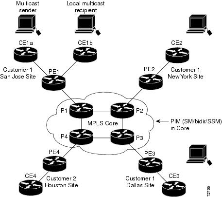
In the following example, a service provider has a multicast customer with offices in San Jose, New York, and Dallas. A one-way multicast presentation is occurring in San Jose. The service provider network supports all three sites that are associated with this customer, in addition to the Houston site of a different enterprise customer.
The default MDT for the enterprise customer consists of provider routers P1, P2, and P3 and their associated PE routers. PE4 is not part of the default MDT, because it is associated with a different customer. Figure 34-1 shows that no data flows along the default MDT, because no one outside of San Jose has joined the multicast.
Figure 34-1 Default Multicast Distribution Tree Overview
An employee in New York joins the multicast session. The PE router that is associated with the New York site sends a join request that flows across the default MDT for the multicast domain of the customer. PE1, the PE router that is associated with the multicast session source, receives the request. Figure 34-2 depicts that the PE router forwards the request to the CE router that is associated with the multicast source (CE1a).
Figure 34-2 Initializing the Data MDT
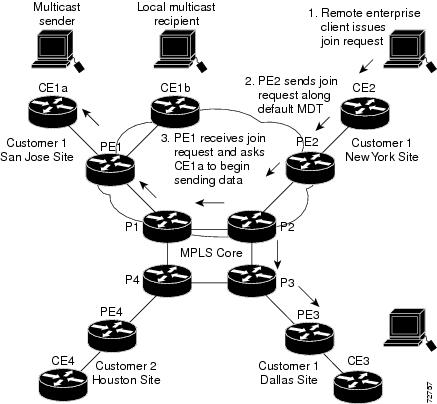
The CE router (CE1a) begins to send the multicast data to the associated PE router (PE1), which sends the multicast data along the default MDT. Immediately after sending the multicast data, PE1 recognizes that the multicast data exceeds the bandwidth threshold for which a data MDT should be created. Therefore, PE1 creates a data MDT, sends a message to all routers using the default MDT that contains information about the data MDT, and, three seconds later, begins sending the multicast data for that particular stream using the data MDT. Only PE2 has interested receivers for this source, so only PE2 joins the data MDT and receives traffic on it. (If the data MDT had not been configured and only the default MDT had been configured, all the customer sites would have received the traffic even though they were not interested in it.)
PE routers maintain a PIM relationship with other PE routers over the default MDT and a PIM relationship with its directly attached P routers.
Multicast Tunnel Interface
An MVPN routing and forwarding (MVRF), which is created per multicast domain, requires the router to create a tunnel interface from which all MVRF traffic is sourced. A multicast tunnel interface is an interface that the MVRF uses to access the multicast domain. The interface is a conduit that connects an MVRF and the global MVRF. One tunnel interface is created per MVRF.
Benefits of MVPNs
Information About the BGP Advertisement Method for MVPN Support
This section includes the following topics:
Overview
When you configure the default MDT in a PIM Source Specific Multicast (PIM-SSM) environment rather than a PIM-SM environment, the receiver PE needs information about the source PE and the default MDT. This information is used to send (S, G) joins toward the source PE to build a distribution tree from the source PE without the need for a rendezvous point (RP). The source provider edge (PE) address and default MDT address are sent using the Border Gateway Protocol (BGP).
BGP MDT SAFI
BGP MDT SAFI is the BGP advertisement method that is used for MVPNs. In the current release, only IPv4 is supported. MDT SAFI has the following settings:
In Cisco NX-OS, the source PE address and the MDT address are passed to PIM using BGP MDT SAFI updates. The Route Descriptor (RD) type has changed to RD type 0 and BGP determines the best path for the MDT updates before passing the information to PIM.
You must configure the MDT SAFI address family for BGP neighbors by using the address-family ipv4 mdt command. You must still enable neighbors that do not support the MDT SAFI for the MDT SAFI in the local BGP configuration. Prior to the MDT SAFI, additional BGP configuration from the VPNv4 unicast configuration was not needed to support MVPNs.
Licensing Requirements for MVPNs
|
|
|
|---|---|
MVPNs require an MPLS license. For a complete explanation of the Cisco NX-OS licensing scheme and how to obtain and apply licenses, see the Cisco NX-OS Licensing Guide. |
Prerequisites for MVPNs
Configuring MVPNs has the following prerequisites:
- Ensure that you have configured MPLS and Label Distribution Protocol (LDP) in your network. All routers in the core, including the PE routers, must be able to support MPLS forwarding. VPNv4 routes are not installed by BGP if labeled paths do not exist for PE source addresses.
- Ensure that you have installed the correct license for MPLS and any other features you will be using with MPLS.
Guidelines and Limitations for MVPNs
MVPNs have the following configuration guidelines and limitations:
- Bidirectional Forwarding Detection (BFD) is not supported on the Multicast Tunnel Interface (MTI).
- By default, the BGP update source is used as the source of the MVPN tunnel. However, you can use the mdt source to override the BGP update source and provide a different source to the multicast tunnel.
- Cisco NX-OS Release 5.2(4) and later 5.x releases as well as Cisco NX-OS Release 6.1(1) and later 6.x releases support multicast GRE tunnel interfaces for PE-CE routing with MVPN.
MDT SAFI has the following configuration and limitations guidelines:
Default Settings for MVPNs
Table 34-1 lists the default settings for MVPN parameters.
|
|
|
|---|---|
mdt mtu mtu1 |
|
mdt data bidir-enable2 |
|
mdt default asm-use-shared-tree [only]3 |
Configuring MVPNs
This section includes the following topics:
- Enabling Features
- Enabling PIM on Interfaces
- Configuring a Default MDT for a VRF
- Enforcing MDT SAFI for a VRF
- Configuring the MDT Address Family in BGP for MVPNs
- Configuring a Data MDT
Enabling Features
You enable required features by using the detailed steps in this section. This procedure is required for enabling features.

Note![]() Some protocols, such as rip/ospf, must be running both on customer VRFs as well as the core.
Some protocols, such as rip/ospf, must be running both on customer VRFs as well as the core.
SUMMARY STEPS
DETAILED STEPS
|
|
|
|
|---|---|---|
Enables the MPLS Layer 3 VPN feature, which is needed to determine unicast routes across sites. |
||
Enabling PIM on Interfaces
You can configure Protocol Independent Multicast (PIM) on all interfaces that are used for IP multicast. We recommend that you configure PIM sparse mode on all physical interfaces of provider edge (PE) routers that connect to the backbone. We also recommend that you configure PIM sparse mode on all loopback interfaces if they are used for BGP peering or if their IP address is used as an RP address for PIM.
Note![]() This procedure is required for enabling PIM on interfaces. For more information on PIM, see the Cisco Nexus 7000 Series NX-OS Multicast Routing Configuration Guide.
This procedure is required for enabling PIM on interfaces. For more information on PIM, see the Cisco Nexus 7000 Series NX-OS Multicast Routing Configuration Guide.
SUMMARY STEPS
DETAILED STEPS
|
|
|
|
|---|---|---|
Configuring a Default MDT for a VRF
You can configure a default MDT for a VRF.
The default MDT must be the same that is configured on all routers that belong to the same VPN. The source IP address is the address that you use to source the BGP sessions.
SUMMARY STEPS
DETAILED STEPS
|
|
|
|
|---|---|---|
Configures the multicast address range for data MDTs for a VRF as follows: |
Enforcing MDT SAFI for a VRF
You can enforce the use of MDT subsequent address family identifiers (SAFI) for a VRF, or you can configure MDT to interoperate with peers that do not support MDT SAFI.
SUMMARY STEPS
DETAILED STEPS
Configuring the MDT Address Family in BGP for MVPNs
You can configure an MDT address family session on PE routers to establish MDT peering sessions for MVPNs.
Use the address-family ipv4 mdt command under neighbor mode to configure an MDT address-family session. MDT address-family sessions are used to pass the source PE address and MDT address to PIM using BGP MDT Subaddress Family Identifier (SAFI) updates.
Prerequisites
Before MVPN peering can be established through an MDT address family, you must configure MPLS in the BGP network and multiprotocol BGP on PE routers that provide VPN services to CE routers.
SUMMARY STEPS
5.![]() address-family ipv4 unicast
address-family ipv4 unicast
6.![]() route-target import route-target-ext-community
route-target import route-target-ext-community
7.![]() route-target export route-target-ext-community
route-target export route-target-ext-community
10.![]() address-family {vpnv4} [ unicast]
address-family {vpnv4} [ unicast]
11.![]() address-family {ipv4} [ unicast]
address-family {ipv4} [ unicast]
15.![]() address-family vpnv4 [ unicast]
address-family vpnv4 [ unicast]
17.![]() (Optional) show bgp {ipv4} unicast neighbors vrf vrf-name
(Optional) show bgp {ipv4} unicast neighbors vrf vrf-name
DETAILED STEPS
Configuring a Data MDT
Multicast groups that are used to create the data MDT are dynamically chosen from a pool of configured IP addresses. If the number of streams is greater than the maximum number of data MDTs per VRF per PE, multiple streams share the same data MDT. See Appendix A, “Configuration Limits for Cisco NX-OS MPLS” for information on the maximum supported number of data MDTs per VRF per PE.
Prerequisites
Before configuring a data MDT, you must configure the default MDT on the VRF.
SUMMARY STEPS
3.![]() mdt data data prefix [ threshold threshold-value ] [ routemap policy-name ]
mdt data data prefix [ threshold threshold-value ] [ routemap policy-name ]
DETAILED STEPS
Verifying the MVPN Configuration
To display the MVPN configuration, perform one of the following tasks:
Configuration Examples for MVPNs
This section includes the following configuration examples:
Example: Configuring MVPN
The following example shows how to configure an MVPN with two contexts:
Example: Configuring the Multicast Address Range for Data MDTs
The following example shows how to assign to the VPN routing instance a VRF named blue. The MDT default for a VPN VRF is 10.1.1.1, and the multicast address range for MDTs is 10.1.2.0 with wildcard bits of 0.0.0.3:
Additional References for MVPNs
For additional information related to MVPN configuration, see the following sections:
Related Documents
Standards
|
|
|
|---|---|
No new or modified standards are supported by this feature, and support for existing standards has not been modified by this feature. |
MIBs
|
|
|
|---|---|
To locate and download MIBs for selected platforms, releases, and feature sets, use Cisco MIB Locator found at the following URL: |
Feature History for MVPNs
Table 34-2 lists the release history for this feature.
|
|
|
|
|---|---|---|
Added support for multicast GRE tunnel interfaces for PE-CE routing with MVPN. |
||
Added support for multicast GRE tunnel interfaces for PE-CE routing with MVPN. |
||
 Feedback