Cisco Nexus 7000 Series NX-OS Unicast Routing Configuration Guide, Release 4.x
Bias-Free Language
The documentation set for this product strives to use bias-free language. For the purposes of this documentation set, bias-free is defined as language that does not imply discrimination based on age, disability, gender, racial identity, ethnic identity, sexual orientation, socioeconomic status, and intersectionality. Exceptions may be present in the documentation due to language that is hardcoded in the user interfaces of the product software, language used based on RFP documentation, or language that is used by a referenced third-party product. Learn more about how Cisco is using Inclusive Language.
- Updated:
- December 14, 2009
Chapter: Configuring IS-IS
- Information about IS-IS
- Licensing Requirements for IS-IS
- Prerequisites for IS-IS
- Configuration Guidelines and Limitations
- Configuring IS-IS
- IS-IS Configuration Modes
- Enabling the IS-IS Feature
- Creating an IS-IS Instance
- Restarting an IS-IS Instance
- Shutting Down IS-IS
- Configuring IS-IS on an Interface
- Shutdown IS-IS on an Interface
- Configuring IS-IS Authentication in an Area
- Configuring IS-IS Authentication on an Interface
- Configuring a Mesh Group
- Configuring a Designated Intermediate System
- Configuring Dynamic Host Exchange
- Setting the Overload Bit
- Configuring the Attached Bit
- Configuring the Transient Mode for Hello Padding
- Configuring a Summary Address
- Configuring Redistribution
- Limiting the Number of Redistributed Routes
- Configuring a Graceful Restart
- Configuring Virtualization
- Tuning IS-IS
- Verifying IS-IS Configuration
- Displaying IS-IS Statistics
- IS-IS Example Configuration
- Related Topics
- Default Settings
- Additional References
- Feature History for IS-IS
Configuring IS-IS
This chapter describes how to configure Integrated Intermediate System-to-Intermediate System (IS-IS).
This chapter includes the following sections:
•![]() Licensing Requirements for IS-IS
Licensing Requirements for IS-IS
•![]() Configuration Guidelines and Limitations
Configuration Guidelines and Limitations
•![]() Verifying IS-IS Configuration
Verifying IS-IS Configuration
Information about IS-IS
IS-IS is an Interior Gateway Protocol (IGP) based on Standardization (ISO)/International Engineering Consortium (IEC) 10589. Cisco NX-OS supports Internet Protocol version 4 (IPv4). IS-IS is a dynamic link-state routing protocol that can detect changes in the network topology and calculate loop-free routes to other nodes in the network. Each router maintains a link-state database that describes the state of the network and sends packets on every configured link to discover neighbors. IS-IS floods the link-state information across the network to each neighbor. The router also sends advertisements and updates on the link-state database through all the existing neighbors.

Note ![]() Cisco NX-OS does not support IPv6 for IS-IS.
Cisco NX-OS does not support IPv6 for IS-IS.
This section includes the following topics:
•![]() High Availability and Graceful Restart
High Availability and Graceful Restart
IS-IS Overview
IS-IS sends a hello packet out every configured interface to discover IS-IS neighbor routers. The hello packet contains information, such as the authentication, area, and supported protocols, which the receiving interface uses to determine compatibility with the originating interface. The hello packets are also padded to ensure that IS-IS establishes adjacencies only with interfaces that have matching maximum transmission unit (MTU) settings. Compatible interfaces form adjacencies, which update routing information in the link-state database through link-state update messages (LSPs). By default, the router sends a periodic LSP refresh every 10 minutes and the LSPs remain in the link-state database for 20 minutes (the LSP lifetime). If the router does not receive an LSP refresh before the end of the LSP lifetime, the router deletes the LSP from the database.
The LSP interval must be less than the LSP lifetime or the LSPs time out before they are refreshed.
IS-IS sends periodic hello packets to adjacent routers. If you configure transient mode for hello packets, these hello packets do not include the excess padding used before IS-IS establishes adjacencies. If the MTU value on adjacent routers changes, IS-IS can detect this change and send padded hello packets for a period of time. IS-IS uses this feature to detect mismatched MTU values on adjacent routers. See the "Configuring the Transient Mode for Hello Padding" section.
IS-IS Areas
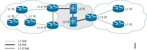
You can design IS-IS networks as a single area that includes all routers in the network or as multiple areas that connect into a backbone or Level 2 area. Routers in a nonbackbone area are Level 1 routers which establish adjacencies within a local area (intra-area routing). Level 2 area routers establish adjacencies to other Level 2 routers and perform routing between Level 1 areas (inter-area routing). A router can have both Level 1 and Level 2 areas configured. These Level 1/Level 2 routers act as area border routers which route information from the local area to the Level 2 backbone area (see Figure 9-1).
Within a Level 1 area, routers know how to reach all other routers in that area. The Level 2 routers know how to reach other area border routers and other Level 2 routers. Level 1/Level 2 routers straddle the boundary between two areas, routing traffic to and from the Level 2 backbone area. Level1/Level2 routers use the attached (ATT) bit signal Level 1 routers to set a default route to this Level1/Level2 router to connect to the Level 2 area.
In some instances, such as when you have two or more Level1/Level 2 routers in an area, you may want to control which Level1/Level2 router that the Level 1 routers use as the default route to the Level 2 area. You can configure which Level1/Level2 router sets the attached bit. See the "Verifying IS-IS Configuration" section.
Each IS-IS instance in Cisco NX-OS supports either a single Level 1 or Level 2 area, or one of each. By default, all IS-IS instances automatically support Level 1 and Level 2 routing.
Figure 9-1 IS-IS Network Divided into Areas
An autonomous system boundary router (ASBR) advertises external destinations throughout the IS-IS autonomous system. External routes are the routes redistributed into IS-IS from any other protocol.
NET and System ID
Each IS-IS instance has an associated network entity title (NET). The NET is comprised of the IS-IS system ID, which uniquely identifies this IS-IS instance in the area and the area ID. For example, if the NET is 47.0004.004d.0001.0001.0c11.1111.00, then the system ID is 0000.0c11.1111.00 and the area is ID 47.0004.004d.0001.
Designated Intermediate System
IS-IS uses a designated intermediate system (DIS) in broadcast networks to prevent each router from forming unnecessary links with every other router on the broadcast network. IS-IS routers send LSPs to the DIS, which manages all the link-state information for the broadcast network. You can configure the IS-IS priority which IS-IS uses to select the DIS in an area.
Note ![]() No DIS is required on a point-to-point network.
No DIS is required on a point-to-point network.
IS-IS Authentication
You can configure authentication to control adjacencies and the exchange of LSPs. Routers that want to become neighbors must exchange the same password for their configured level of authentication. IS-IS blocks a router that does not have the correct password. You can configure IS-IS authentication globally or for an individual interface for Level 1, Level 2, or both Level 1/Level 2 routing.
IS-IS supports the following authentication methods:
•![]() Clear text—All packets exchanged carry a cleartext 128-bit password.
Clear text—All packets exchanged carry a cleartext 128-bit password.
•![]() MD5 digest—All packets exchanged carry a message digest that is based on a 128-bit key.
MD5 digest—All packets exchanged carry a message digest that is based on a 128-bit key.
To provide protection against passive attacks, IS-IS never sends the MD5 secret key as cleartext through the network In addition, IS-IS includes a sequence number in each packet to protect against replay attacks.
You can use also keychains for hello and LSP authentication. See Cisco Nexus 7000 Series NX-OS Security Configuration Guide, Release 4.x for information on keychain management.
Mesh Groups
A mesh group is a set of interfaces in which all routers reachable over the interfaces have at least one link to every other router. Many links can fail without isolating one or more routers from the network.
In normal flooding, an interface receives a new LSP and floods the LSP out over all other interfaces on the router. With mesh groups, when an interface that is part of a mesh group receives a new LSP, the interface does not flood the new LSP over the other interfaces that are part of that mesh group.
Note ![]() You may want to limit LSPs in certain mesh network topologies to improve network scalability. Limiting LSP floods may also reduce the reliability of the network (in case of failures). For this reason, we recommend that you use mesh groups only if specifically required, and then only after careful network design.
You may want to limit LSPs in certain mesh network topologies to improve network scalability. Limiting LSP floods may also reduce the reliability of the network (in case of failures). For this reason, we recommend that you use mesh groups only if specifically required, and then only after careful network design.
You can also configure mesh groups in block mode for parallel links between routers. In this mode, all LSPs are blocked on that interface in a mesh group after the routers initially exchange their link-state information.
Overload Bit
IS-IS uses the overload bit to tell other routers not to use the local router to forward traffic but to continue routing traffic destined for that local router.
You may want to use the overload bit in these situations:
•![]() The router is in a critical condition.
The router is in a critical condition.
•![]() Graceful introduction and removal of the router to/from the network.
Graceful introduction and removal of the router to/from the network.
•![]() Other (administrative or traffic engineering) reasons. For example, to wait for BGP convergence.
Other (administrative or traffic engineering) reasons. For example, to wait for BGP convergence.
Route Summarization
You can configure a summary aggregate address. Route summarization simplifies route tables by replacing a number of more-specific addresses with an address that represents all the specific addresses. For example, you can replace 10.1.1.0/24, 10.1.2.0/24, and 10.1.3.0/24 with one summary address, 10.1.0.0/16.
If more specific routes are in the routing table, IS-IS advertises the summary address with a metric equal to the minimum metric of the more specific routes.
Note ![]() Cisco NX-OS does not support automatic route summarization.
Cisco NX-OS does not support automatic route summarization.
Route Redistribution
You can use IS-IS to redistribute static routes, routes learned by other IS-IS autonomous systems, or routes from other protocols. You must configure a route map with the redistribution to control which routes are passed into IS-IS. A route map allows you to filter routes based on attributes such as the destination, origination protocol, route type, route tag, and so on. For more information, see Chapter 16 "Configuring Route Policy Manager."
Whenever you redistribute routes into an IS-IS routing domain, Cisco NX-OS does not, by default, redistribute the default route into the IS-IS routing domain. You can generate a default route into IS-IS, which can be controlled by a route policy.
You also configure the default metric that is used for all imported routes into IS-IS.
Load Balancing
You can use load balancing to allow a router to distribute traffic over all the router network ports that are the same distance from the destination address. Load balancing increases the utilization of network segments and increases effective network bandwidth.
Cisco NX-OS supports the Equal Cost Multiple Paths (ECMP) feature with up to 16 equal-cost paths in the IS-IS route table and the unicast RIB. You can configure IS-IS to load balance traffic across some or all of those paths.
Virtualization Support
Cisco NX-OS supports multiple instances of the IS-IS protocol that runs on the same system. IS-IS supports Virtual Routing and Forwarding instances (VRFs). VRFs exist within virtual device contexts (VDCs). You can configure up to four IS-IS instances in a VDC.
By default, Cisco NX-OS places you in the default VDC and default VRF unless you specifically configure another VDC and VRF. See the Cisco Nexus 7000 Series NX-OS Virtual Device Context Configuration Guide, Release 4.xe and Chapter 14 "Configuring Layer 3 Virtualization."
High Availability and Graceful Restart
Cisco NX-OS supports RFC 3847 for graceful restart of IS-IS. IS-IS automatically restarts if the process experiences problems. After the restart, IS-IS initiates a graceful restart so that the platform is not taken out of the network topology. If you manually restart IS-IS, it performs a graceful restart and applies the running configuration.
Note ![]() You must enable graceful restart to support in-service software upgrades (ISSU) for IS-IS. If you disable graceful restart, Cisco NX-OS issues a warning that ISSU cannot be supported with this configuration.
You must enable graceful restart to support in-service software upgrades (ISSU) for IS-IS. If you disable graceful restart, Cisco NX-OS issues a warning that ISSU cannot be supported with this configuration.
Multiple IS-IS Instances
Cisco NX-OS supports a maximum of four instances of the IS-IS protocol that run on the same node. You cannot configure multiple instances over the same interface. Every instance uses the same system router ID.
Licensing Requirements for IS-IS
The following table shows the licensing requirements for this feature:
Prerequisites for IS-IS
IS-IS has the following prerequisites:
•![]() You must enable the IS-IS feature (see the "Enabling the IS-IS Feature" section).
You must enable the IS-IS feature (see the "Enabling the IS-IS Feature" section).
•![]() If you configure VDCs, install the Advanced Services license and enter the desired VDC (see the Cisco Nexus 7000 Series NX-OS Virtual Device Context Configuration Guide, Release 4.x).
If you configure VDCs, install the Advanced Services license and enter the desired VDC (see the Cisco Nexus 7000 Series NX-OS Virtual Device Context Configuration Guide, Release 4.x).
Configuration Guidelines and Limitations
IS-IS has the following configuration guidelines and limitations:
•![]() You can configure a maximum of four IS-IS instances per VDC.
You can configure a maximum of four IS-IS instances per VDC.
•![]() Because the default reference bandwidth is different for Cisco NX-OS and Cisco IOS, the advertised tunnel IS-IS metric is different for these two operating systems.
Because the default reference bandwidth is different for Cisco NX-OS and Cisco IOS, the advertised tunnel IS-IS metric is different for these two operating systems.
Configuring IS-IS
To configure IS-IS, follow these steps:
Step 1 ![]() Enable the IS-IS feature (see the "Enabling the IS-IS Feature" section).
Enable the IS-IS feature (see the "Enabling the IS-IS Feature" section).
Step 2 ![]() Create an IS-IS instance (see the "Creating an IS-IS Instance" section).
Create an IS-IS instance (see the "Creating an IS-IS Instance" section).
Step 3 ![]() Add an interface to the IS-IS instance (see the "Configuring IS-IS on an Interface" section).
Add an interface to the IS-IS instance (see the "Configuring IS-IS on an Interface" section).
Step 4 ![]() Configure optional features, such as authentication, mesh groups, and dynamic host exchange.
Configure optional features, such as authentication, mesh groups, and dynamic host exchange.
This section contains the following topics:
•![]() Configuring IS-IS on an Interface
Configuring IS-IS on an Interface
•![]() Shutdown IS-IS on an Interface
Shutdown IS-IS on an Interface
•![]() Configuring IS-IS Authentication in an Area
Configuring IS-IS Authentication in an Area
•![]() Configuring IS-IS Authentication on an Interface
Configuring IS-IS Authentication on an Interface
•![]() Configuring a Designated Intermediate System
Configuring a Designated Intermediate System
•![]() Configuring Dynamic Host Exchange
Configuring Dynamic Host Exchange
•![]() Configuring a Summary Address
Configuring a Summary Address
•![]() Limiting the Number of Redistributed Routes
Limiting the Number of Redistributed Routes
Note ![]() If you are familiar with the Cisco IOS CLI, be aware that the Cisco NX-OS commands for this feature might differ from the Cisco IOS commands that you would use.
If you are familiar with the Cisco IOS CLI, be aware that the Cisco NX-OS commands for this feature might differ from the Cisco IOS commands that you would use.
IS-IS Configuration Modes
The following sections show how to enter each of the configuration modes. From a mode, you can enter the ? command to display the commands available in that mode.
This section includes the following topics:
•![]() Router Address Family Configuration Mode
Router Address Family Configuration Mode
Router Configuration Mode
The following example shows how to enter router configuration mode:
switch#: config t
switch(config)# router isis isp
switch(config-router)#
Router Address Family Configuration Mode
The following example shows how to enter router address family configuration mode:
switch(config)# router isis isp
switch(config-router)# address-family ipv4 unicast
switch(config-router-af)#
Enabling the IS-IS Feature
You must enable the IS-IS feature before you can configure IS-IS.
BEFORE YOU BEGIN
Ensure that you are in the correct VDC (or use the switchto vdc command).
SUMMARY STEPS
1. ![]() config t
config t
2. ![]() feature isis
feature isis
3. ![]() show feature
show feature
4. ![]() copy running-config startup-config
copy running-config startup-config
DETAILED STEPS
Use the no feature isis command to disable the IS-IS feature and remove all associated configuration.
|
|
|
|---|---|
no feature isis
Example: switch(config)# no feature isis |
Disables the IS-IS feature and removes all associated configuration. |
Creating an IS-IS Instance
You can create an IS-IS instance and configure the area level for that instance.
BEFORE YOU BEGIN
Ensure that you have enabled the IS-IS feature (see the "Enabling the IS-IS Feature" section).
Ensure that you are in the correct VDC (or use the switchto vdc command).
SUMMARY STEPS
1. ![]() config t
config t
2. ![]() router isis instance-tag
router isis instance-tag
3. ![]() net network-entity-title
net network-entity-title
4. ![]() is-type {level-1 | level-2 | level-1-2}
is-type {level-1 | level-2 | level-1-2}
5. ![]() show isis [vrf vrf-name] process
show isis [vrf vrf-name] process
6. ![]() copy running-config startup-config
copy running-config startup-config
DETAILED STEPS
Use the no router isis command to remove the IS-IS instance and the associated configuration.
|
|
|
|---|---|
no router isis instance-tag
Example: switch(config)# no router isis Enterprise |
Deletes the IS-IS instance and all associated configuration. |
Note ![]() You must also remove any IS-IS commands configured in interface mode to completely remove all configuration for the IS-IS instance.
You must also remove any IS-IS commands configured in interface mode to completely remove all configuration for the IS-IS instance.
You can configure the following optional parameters for IS-IS:
|
|
|
|---|---|
distance value
Example: switch(config-router)# distance 30 |
Sets the administrative distance for IS-IS. The range is from 1 to 255. The default is 115. See the "Administrative Distance" section. |
log-adjacency-changes
Example: switch(config-router)# log-adjacency-changes |
Sends a system message whenever an IS-IS neighbor changes state. |
lsp-mtu size Example: switch(config-router)# lsp-mtu 600 |
Sets the MTU for LSPs in this IS-IS instance. The range is from 128 to 4352 bytes. The default is 1492. |
maximum-paths number Example: switch(config-router)# maximum-paths 6 |
Configures the maximum number of equal-cost paths that IS-IS maintains in the route table. The range is from 1 to 16. The default is 4. |
reference-bandwidth bandwidth-value {Mbps | Gbps}
Example: switch(config-router)# reference-bandwidth 100 Gbps |
Sets the default reference bandwidth used for calculating the IS-IS cost metric. The range is from 1 to 4000 Gbps. The default is 40 Gbps. |
The following example shows how to create an IS-IS instance in a level 2 area:
switch# config t
switch(config)# router isis Enterprise
switch(config-router)# net 47.0004.004d.0001.0001.0c11.1111.00
switch(config-router)# is-type level 2
switch(config-router)# copy running-config startup-config
To clear neighbor statistics and remove adjacencies, use the following command in router configuration mode:
Restarting an IS-IS Instance
You can restart an IS-IS instance. This clears all neighbors for the instance.
To restart an IS-IS instance and remove all associated neighbors, use the following command:
|
|
|
|---|---|
restart isis instance-tag
Example: switch(config)# restart isis Enterprise |
Restarts the IS-IS instance and removes all neighbors. |
Shutting Down IS-IS
You can shut down the IS-IS instance. This disables this IS-IS instance and retains the configuration.
To shut down the IS-IS instance, use the following command in router configuration mode:
|
|
|
|---|---|
shutdown
Example: switch(config-router)# shutdown |
Disables the IS-IS instance. |
Configuring IS-IS on an Interface
You can add an interface to an IS-IS instance.
BEFORE YOU BEGIN
Ensure that you have enabled the IS-IS feature (see the "Enabling the IS-IS Feature" section).
Ensure that you are in the correct VDC (or use the switchto vdc command).
SUMMARY STEPS
1. ![]() config t
config t
2. ![]() interface interface-type slot/port
interface interface-type slot/port
3. ![]() medium { broadcast | p2p} (Optional)
medium { broadcast | p2p} (Optional)
4. ![]() ip router isis instance-tag
ip router isis instance-tag
5. ![]() show isis [vrf vrf-name] [instance-tag] interface [interface-type slot/port]
show isis [vrf vrf-name] [instance-tag] interface [interface-type slot/port]
6. ![]() copy running-config startup-config
copy running-config startup-config
DETAILED STEPS
You can configure the following optional parameters for IS-IS in interface mode:
The following example shows how to add Ethernet 1/2 interface to an IS-IS instance:
switch# config t
switch(config)# interface ethernet 1/2
switch(config-if)# ip router isis Enterprise
switch(config-if)# copy running-config startup-config
Shutdown IS-IS on an Interface
You can gracefully shut down IS-IS on an interface. This removes all adjacencies and stops IS-IS traffic on this interface but preserves the IS-IS configuration.
To disable IS-IS on an interface, use the following command in interface configuration mode:
|
|
|
|---|---|
switch(config-if)# isis shutdown
Example: switch(config-router)# isis shutdown |
Disables IS-IS on this interface. The IS-IS interface configuration remains. |
Configuring IS-IS Authentication in an Area
You can configure IS-IS to authenticate LSPs in an area.
BEFORE YOU BEGIN
Ensure that you have enabled the IS-IS feature (see the "Enabling the IS-IS Feature" section).
Ensure that you are in the correct VDC (or use the switchto vdc command).
SUMMARY STEPS
1. ![]() config t
config t
2. ![]() router isis instance-tag
router isis instance-tag
3. ![]() authentication-type {cleartext | md5} {level-1 | level-2}
authentication-type {cleartext | md5} {level-1 | level-2}
4. ![]() authentication key-chain key {level-1 | level-2}
authentication key-chain key {level-1 | level-2}
5. ![]() authentication-check {level-1 | level-2}
authentication-check {level-1 | level-2}
6. ![]() copy running-config startup-config
copy running-config startup-config
DETAILED STEPS
The following example shows how to configure cleartext authentication on an IS-IS instance:
switch# config t
switch(config)# router isis Enterprise
switch(config-router)# authentication-type cleartext level-2
switch(config-router)# authentication key-chain ISISKey level-2
switch(config-router)# copy running-config startup-config
Configuring IS-IS Authentication on an Interface
You can configure IS-IS to authenticate Hello packets on an interface.
BEFORE YOU BEGIN
Ensure that you have enabled the IS-IS feature (see the "Enabling the IS-IS Feature" section).
Ensure that you are in the correct VDC (or use the switchto vdc command).
SUMMARY STEPS
1. ![]() config t
config t
2. ![]() interface interface-type slot/port
interface interface-type slot/port
3. ![]() isis authentication-type {cleartext | md5} {level-1 | level-2}
isis authentication-type {cleartext | md5} {level-1 | level-2}
4. ![]() isis authentication key-chain key {level-1 | level-2}
isis authentication key-chain key {level-1 | level-2}
5. ![]() isis authentication-check {level-1 | level-2}
isis authentication-check {level-1 | level-2}
6. ![]() copy running-config startup-config
copy running-config startup-config
DETAILED STEPS
The following example shows how to configure cleartext authentication on an IS-IS instance:
switch# config t
switch(config)# interface ethernet 1/2
switch(config-if)# isis authentication-type cleartext level-2
switch(config-if)# isis authentication key-chain ISISKey
switch(config-if)# copy running-config startup-config
Configuring a Mesh Group
You can add an interface to a mesh group to limit the amount of LSP flooding for interfaces in that mesh group. You can optionally block all LSP flooding on an interface in a mesh group.
To add an interface to a mesh group, use the following command in interface configuration mode:
|
|
|
|---|---|
isis mesh-group {blocked | mesh-id}
Example: switch(config-if)# isis mesh-group 1 |
Adds this interface to a mesh group. The range is from 1 to 4294967295. |
Configuring a Designated Intermediate System
You can configure a router to become the designated intermediate system (DIS) for a multiaccess network by setting the interface priority.
To configure the DIS, use the following command in interface configuration mode:
|
|
|
|---|---|
isis priority number {level-1 | level-2}
Example: switch(config-if)# isis priority 100 level-1 |
Sets the priority for DIS selection. The range is from 0 to 127. The default is 64. |
Configuring Dynamic Host Exchange
You can configure IS-IS to map between the system ID and the hostname for a router using dynamic host exchange.
To configure dynamic host exchange, use the following command in router configuration mode:
|
|
|
|---|---|
hostname dynamic
Example: switch(config-router)# hostname dynamic |
Enables dynamic host exchange. |
Setting the Overload Bit
You can configure the router to signal other routers not to use this router as an intermediate hop in their shortest path first (SPF) calculations. You can optionally configure the overload bit temporarily on startup, until BGP converges.
In addition to setting the overload bit, you might also want to suppress certain types of IP prefix advertisements from LSPs for Level 1 or Level 2 traffic.
To set the overload bit, use the following command in router configuration mode:
Configuring the Attached Bit
You can configure the attached bit to control which Level1/Level2 router that the Level 1 routers use as the default route to the Level 2 area. If you disable setting the attached bit, the Level 1 routers will not use this Level1/Level 2 router to reach the Level 2 area.
To configure the attached bit for a Level1/Level2 router, use the following command in router configuration mode:
|
|
|
|---|---|
[no] attached-bit Example: switch(config-router)# no attached-bit |
Configures the Level1/Level 2 router to set the attached bit. This is enabled by default. |
Configuring the Transient Mode for Hello Padding
You can configure the transient mode for hello padding to pad hello packets when IS-IS establishes adjacency and remove that padding after IS-IS establishes adjacency.
To configure the mode for hello padding, use the following command in router configuration mode:
Configuring a Summary Address
You can create aggregate addresses that are represented in the routing table by a summary address. One summary address can include multiple groups of addresses for a given level. Cisco NX-OS advertises the smallest metric of all the more-specific routes.
BEFORE YOU BEGIN
Ensure that you have enabled the IS-IS feature (see the "Enabling the IS-IS Feature" section).
Ensure that you are in the correct VDC (or use the switchto vdc command).
SUMMARY STEPS
1. ![]() config t
config t
2. ![]() router isis instance-tag
router isis instance-tag
3. ![]() address-family ipv4 {unicast | multicast}
address-family ipv4 {unicast | multicast}
4. ![]() summary-address ip-prefix/mask-len {level-1 | level-2 | level-1-2}
summary-address ip-prefix/mask-len {level-1 | level-2 | level-1-2}
5. ![]() show isis [vrf vrf-name] ip summary-address ip-prefix [longer-prefixes]
show isis [vrf vrf-name] ip summary-address ip-prefix [longer-prefixes]
6. ![]() copy running-config startup-config
copy running-config startup-config
DETAILED STEPS
The following example shows how to configure an IPv4 unicast summary address for IS-IS:
switch# config t
switch(config)# router isis Enterprise
switch(config-router)# address-family ipv4 unicast
switch(config-router-af)# summary-address 192.0.2.0/24 level-2
switch(config-router-af)# copy running-config startup-config
Configuring Redistribution
You can configure IS-IS to accept routing information from another routing protocol and redistribute that information through the IS-IS network. You can optionally assign a default route for redistributed routes.
BEFORE YOU BEGIN
Ensure that you have enabled the IS-IS feature (see the "Enabling the IS-IS Feature" section).
Ensure that you are in the correct VDC (or use the switchto vdc command).
SUMMARY STEPS
1. ![]() config t
config t
2. ![]() router isis instance-tag
router isis instance-tag
3. ![]() address-family ipv4 unicast
address-family ipv4 unicast
4. ![]() redistribute {bgp as | direct |{eigrp | isis | ospf | ospfv3 | rip} instance-tag | static} route-map map-name
redistribute {bgp as | direct |{eigrp | isis | ospf | ospfv3 | rip} instance-tag | static} route-map map-name
5. ![]() default-information originate [always] [route-map map-name]
default-information originate [always] [route-map map-name]
6. ![]() distribute {level-1 | level-2} into {level-1 | level-2} {route-map route-map | all}
distribute {level-1 | level-2} into {level-1 | level-2} {route-map route-map | all}
7. ![]() show isis [vrf vrf-name] ip route ip-prefix [detail | longer-prefixes [summary | detail]]
show isis [vrf vrf-name] ip route ip-prefix [detail | longer-prefixes [summary | detail]]
8. ![]() copy running-config startup-config
copy running-config startup-config
DETAILED STEPS
|
|
|
|
|---|---|---|
Step 1 |
config t
Example: switch# config t switch(config)# |
Enters configuration mode. |
Step 2 |
router isis instance-tag
Example: switch(config)# router isis Enterprise switch(config-router)# |
Creates a new IS-IS instance with the configured instance tag. |
Step 3 |
address-family ipv4 unicast
Example: switch(config-router)# address-family ipv4 unicast switch(config-router-af)# |
Enters address family configuration mode. |
Step 4 |
redistribute {bgp as | {eigrp | isis | ospf | ospfv3 | rip} instance-tag | static | direct} route-map map-name
Example: switch(config-router-af)# redistribute eigrp 201 route-map ISISmap |
Redistributes routes from other protocols into IS-IS. See the "Configuring Route Maps" section for more information about route maps. |
Step 5 |
default-information originate [always] [route-map map-name]
Example: switch(config-router-af)# default-information originate always |
(Optional) Generates a default route into IS-IS. |
Step 6 |
distribute {level-1 | level-2} into {level-1 | level-2} {route-map route-map | all}
Example: switch(config-router-af)# distribute level-1 into level-2 all |
(Optional) Redistributes routes from one IS-IS level to the other IS-IS level. |
Step 7 |
show isis [vrf vrf-name] ip route ip-prefix [detail | longer-prefixes [summary | detail]]
Example: switch(config-router-af)# show isis ip route |
(Optional) Shows the routes IS-IS. |
Step 8 |
copy running-config startup-config
Example: switch(config-router-af)# copy running-config startup-config |
(Optional) Saves this configuration change. |
The following example shows how to redistribute EIGRP into IS-IS:
switch# config t
switch(config)# router isis Enterprise
switch(config-router)# address-family ipv4 unicast
switch(config-router-af)# redistribute eigrp 201 route-map ISISmap
switch(config-router-af)# copy running-config startup-config
Limiting the Number of Redistributed Routes
Route redistribution can add many routes to the IS-IS route table. You can configure a maximum limit to the number of routes accepted from external protocols. IS-IS provides the following options to configure redistributed route limits:
•![]() Fixed limit—Log a message when IS-IS reaches the maximum the configured maximum. IS-IS does not accept any more redistributed routes. You can optionally configure a threshold percentage of the maximum where IS-IS will log a warning when that threshold is passed.
Fixed limit—Log a message when IS-IS reaches the maximum the configured maximum. IS-IS does not accept any more redistributed routes. You can optionally configure a threshold percentage of the maximum where IS-IS will log a warning when that threshold is passed.
•![]() Warning only—Log a warning only when IS-IS reaches the maximum. IS-IS continues to accept redistributed routes.
Warning only—Log a warning only when IS-IS reaches the maximum. IS-IS continues to accept redistributed routes.
•![]() Withdraw—Start the timeout period when IS-IS reaches the maximum. After the timeout period, IS-IS requests all redistributed routes if the current number of redistributed routes is less than the maximum limit. If the current number of redistributed routes is at the maximum limit, IS-IS withdraws all redistributed routes. You must clear this condition before IS-IS accepts more redistributed routes.
Withdraw—Start the timeout period when IS-IS reaches the maximum. After the timeout period, IS-IS requests all redistributed routes if the current number of redistributed routes is less than the maximum limit. If the current number of redistributed routes is at the maximum limit, IS-IS withdraws all redistributed routes. You must clear this condition before IS-IS accepts more redistributed routes.
You can optionally configure the timeout period.
BEFORE YOU BEGIN
Ensure that you have enabled the IS-IS feature (see the "Enabling the IS-IS Feature" section).
Ensure that you are in the correct VDC (or use the switchto vdc command).
SUMMARY STEPS
1. ![]() config t
config t
2. ![]() router is-is instance-tag
router is-is instance-tag
3. ![]() redistribute {bgp id | direct | eigrp id | isis id | ospf id | rip id | static} route-map map-name
redistribute {bgp id | direct | eigrp id | isis id | ospf id | rip id | static} route-map map-name
4. ![]() redistribute maximum-prefix max [threshold] [warning-only | withdraw [num-retries timeout]]
redistribute maximum-prefix max [threshold] [warning-only | withdraw [num-retries timeout]]
5. ![]() show running-config eigrp
show running-config eigrp
6. ![]() copy running-config startup-config
copy running-config startup-config
DETAILED STEPS
The following example shows how to limit the number of redistributed routes into IS-IS:
switch# config t
switch(config)# router eigrp isis Enterprise
switch(config-router)# redistribute bgp route-map FilterExternalBGP
switch(config-router)# redistribute maximum-prefix 1000 75
Configuring a Graceful Restart
You can configure a graceful restart for IS-IS.
BEFORE YOU BEGIN
Ensure that you have enabled the IS-IS feature (see the "Enabling the IS-IS Feature" section).
Create the VDCs and VRFs.
Ensure that you are in the correct VDC (or use the switchto vdc command).
SUMMARY STEPS
1. ![]() config t
config t
2. ![]() router isis instance-tag
router isis instance-tag
3. ![]() graceful-restart
graceful-restart
4. ![]() graceful-restart t3 manual time
graceful-restart t3 manual time
5. ![]() show running-config isis
show running-config isis
6. ![]() copy running-config startup-config
copy running-config startup-config
DETAILED STEPS
The following example shows how to enable a graceful restart:
switch# config t
switch(config)# router isis Enterprise
switch(config-router)# graceful-restart
switch(config-router)# copy running-config startup-config
Configuring Virtualization
You can configure multiple IS-IS instances in each VDC. You can also create multiple VRFs within each VDC and use the same or multiple IS-IS instances in each VRF. You assign an IS-IS interface to a VRF.
You must configure a NET for the configured VRF.
Note ![]() Configure all other parameters for an interface after you configure the VRF for an interface. Configuring a VRF for an interface deletes all the configuration for that interface.
Configure all other parameters for an interface after you configure the VRF for an interface. Configuring a VRF for an interface deletes all the configuration for that interface.
BEFORE YOU BEGIN
Ensure that you have enabled the IS-IS feature (see the "Enabling the IS-IS Feature" section).
Create the VDCs.
Ensure that you are in the correct VDC (or use the switchto vdc command).
SUMMARY STEPS
1. ![]() config t
config t
2. ![]() vrf context vrf_name
vrf context vrf_name
3. ![]() exit
exit
4. ![]() router isis instance-tag
router isis instance-tag
5. ![]() vrf vrf_name
vrf vrf_name
6. ![]() net network-entity-title
net network-entity-title
7. ![]() exit
exit
8. ![]() interface type slot/port
interface type slot/port
9. ![]() vrf member vrf-name
vrf member vrf-name
10. ![]() ip address ip-prefix/length
ip address ip-prefix/length
11. ![]() ip router isis instance-tag
ip router isis instance-tag
12. ![]() show isis [vrf vrf-name] [instance-tag] interface [interface-type slot/port]
show isis [vrf vrf-name] [instance-tag] interface [interface-type slot/port]
13. ![]() copy running-config startup-config
copy running-config startup-config
DETAILED STEPS
The following example shows how to create a VRF and add an interface to the VRF:
switch# config t
switch(config)# vrf context NewVRF
switch(config-vrf)# exit
switch(config)# router isis Enterprise
switch(config-router)# vrf NewVRF
switch(config-router-vrf)# net 47.0004.004d.0001.0001.0c11.1111.00
switch(config-router-vrf)# interface ethernet 1/2
switch(config-if)# vrf membmer NewVRF
switch(config-if)# ip address 192.0.2.1/16
switch(config-if)# ip router isis Enterprise
switch(config-if)# copy running-config startup-config
Tuning IS-IS
You can tune IS-IS to match your network requirements.
You can use the following optional commands in router configuration mode to tune IS-IS:
You can use the following optional command in router address configuration mode:
You can use the following optional commands in interface configuration mode to tune IS-IS:
Verifying IS-IS Configuration
To verify the IS-IS configuration, use the following commands:
For detailed information about the fields in the output from these commands, see the Cisco NX-OS Command Reference.
Displaying IS-IS Statistics
To display IS-IS statistics, use the following commands:
To clear IS-IS configuration statistics, perform one of the following tasks:
IS-IS Example Configuration
The following example shows how to configure IS-IS:
router isis Enterprise
is-type level-1
net 49.0001.0000.0000.0003.00
graceful-restart
address-family ipv4 unicast
default-information originate
interface ethernet 2/1
ip address 192.0.2.1/24
isis circuit-type level-1
ip router isis Enterprise
Related Topics
See the Chapter 16 "Configuring Route Policy Manager" for more information on route maps.
Default Settings
Table 9-1 lists the default settings for IS-IS parameters.
Additional References
For additional information related to implementing IS-IS, see the following sections:
Related Documents
Standards
|
|
|
|---|---|
No new or modified standards are supported by this feature, and support for existing standards has not been modified by this feature. |
— |
Feature History for IS-IS
Table 9-2 lists the release history for this feature.
 Feedback