Overview
This switch chassis includes the following modules:
-
Supervisor modules (one or two)—one of the following types in slots SUP 1 and SUP 2 (numbered from left to right on the chassis):
-
System controllers (two) (N9K-SC-A) in slots SC 1 and SC 2 (numbered from left to right on the chassis)
-
Line cards (up to 16) in slots LC 1 through LC 16 (numbered from top to bottom on the chassis) supported by the same type of fabric module
For compatibility information, please refer to the Line Card and Fabric Module Compatibility data sheets.

Note
Do not mix ACI-mode line cards with NX-OS mode line cards in the same switch.
Note
The N9K-X9716D-GX line card, is not compatible with this switch.
-
Fabric modules in slots FM 1 to FM 6 (numbered from left to right on the chassis)
See the following table for the required fabric module types and quantities that are required for maximum bandwidth.
Table 1. Supported Fabric Modules and Line Cards Fabric Module
Fabric Modules Required for Maximum Bandwidth
Supported Line Cards
N9K-C9516-FM
4
N9K-X9736PQ
N9K-C9516-FM-E2
4
5
5
N9K-X9732C-EX
N9K-X9736C-FX
N9K-X9736Q-FX
Table 2. FM-25 Feature Support Matrix for Cisco Nexus 9000 Series line cards and fabric modules Line cards
X9736PQ
X9736Q-FX
X9732C-EX
X9736C-FX
Fabric modules
C9516-FM-E-E2
No
Yes
Yes
Yes
Note
The fabric modules must be installed in specific slots as follows (installing fabric modules in other slots can cause a module mismatch condition):
-
For three modules, they must be in slots FM 2, FM 4, and FM 6
-
For four modules, they must be in slots FM2, FM 3, FM 4, and FM 6
-
For five modules, they can be in slots FM 1, FM 2, FM 3, FM 4, and FM 6. Alternatively, they can be in Slots FM 2, FM 3, FM 4, FM 5, and FM 6.
-
For five FM-E or FM-E2 modules, they must be in Slots FM 2, FM 3, FM 4, FM 5, and FM 6
-
For six modules, they are in slots FM 1, FM 2, FM 3, FM 4, FM 5, and FM 6
Note
All of the fabric modules in a modular switch must be of the same type.
Note
Fabric slots FM 2, FM 4, or FM 6 must be filled with functioning fabric modules in order to provide power to the fan trays covering those modules.
If fabric slots FM 1, FM 3, or FM 5 are not filled with a fabric module, you must make sure that they have a blank module (N9K-C9516-FM-CV) installed to preserve the designed airflow.
Note
For more information about Line card and fabric module compatibility, see the Cisco Nexus 9500 Platform Line Cards and Fabric Modules Data Sheet.
-
-
Fan trays (three) (N9K-C9516-FAN) in slots FAN 1 to FAN 3 (numbered from left to right on the chassis)
-
Power supplies (up to five with the combined power mode, up to six with the n+1 power redundancy mode, or up to ten with the n+n power redundancy mode) in slots PS 1 to PS 10 (numbered from left to right on the chassis)
-
Cisco Nexus 9500 Series 3-kW AC power supply (N9K-PAC-3000W-B)
-
Cisco Nexus 9500 Series 3-kW Universal AC/DC power supply (N9K-PUV-3000W-B)
-
Cisco Nexus 9500 Series 3.15-kW Dual Input Universal AC/DC power supply (N9K-PUV2-3000W-B)
-
Cisco Nexus 9500 Series 3-kW (-48 V) DC power supply (N9K-PDC-3000W-B)
Note
The switch can be powered by a mix of AC, DC, HVAC/HVDC power sources.
-
Note |
All chassis slots are numbered from left to right or from top to bottom. |
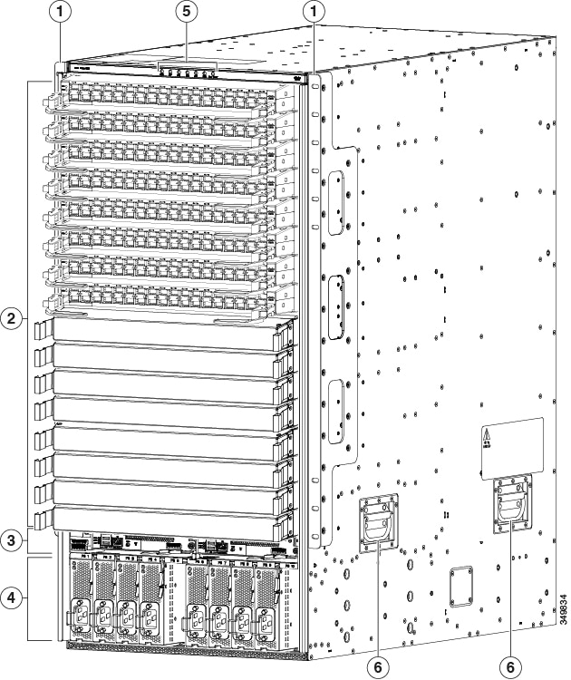
The following figure shows the hardware features seen from the front of the chassis.
|
1 |
2 vertical mounting brackets used to mount the chassis onto a rack |
4 |
3-kW AC, Universal AC/DC, or DC power supplies (AC power supplies shown) |
|
2 |
I/O modules (up to 16) |
5 |
Chassis LEDs |
|
3 |
Supervisor modules (1 or 2) |
6 |
Chassis handles (used only for positioning the chassis on the bottom support rails—do not use these handles for lifting the chassis) |
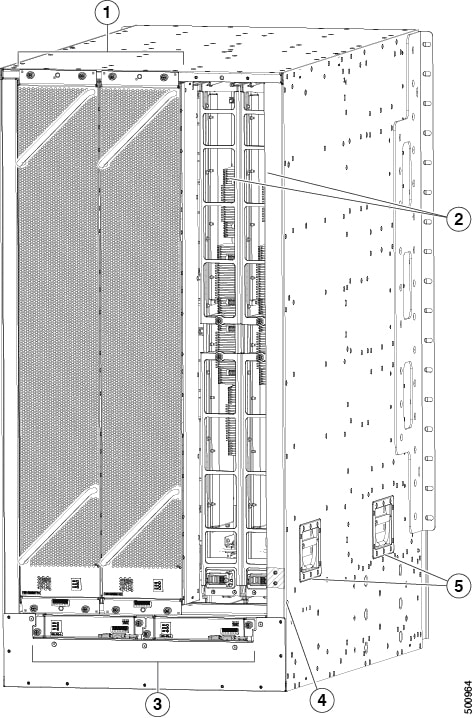
The following figure shows the hardware features seen from the rear of the chassis (one fan tray has been removed to show the fabric modules behind the fan trays).
|
1 |
Fan trays (3—right fan tray not shown in order to display the fabric modules located behind the fan trays) |
4 |
Grounding pad |
|
2 |
Fabric modules (up to 6 with up to 2 behind each fan tray) |
5 |
Chassis handles (used only for positioning the chassis on the bottom support rails—do not use these handles for lifting the chassis) |
|
3 |
System controllers (2) |
 Feedback