- Title
- Table of Contents
- New and Changed Information
- Preface
-
- Configuring Basic MPLS TE
- Configuring Automatic Bandwidth Adjustment for MPLS TE Tunnels
- Configuring MPLS TE RSVP
- Configuring the Path Selection Metric for MPLS TE Tunnels
- Configuring LSP Attributes for MPLS TE
- Configuring MPLS TE Verbatim Paths
- Configuring MPLS TE Forwarding Adjacency
- Configuring MPLS TE Path Protection
- Configuring MPLS TE Fast Reroute Link and Node Protection
-
- Configuring Any Transport over MPLS
- Configuring Any Transport over MPLS Pseudowire Provisioning
- Configuring Ethernet over MPLS
- Configuring EoMPLS Layer 2 VPN Graceful Restart
- Configuring Virtual Private LAN Service
- Configuring Layer 2 VPN Pseudowire Redundancy
- Configuring Layer 2 VPN VPLS Dual-Homing with a vPC
- Configuration Limits for Cisco NX-OS MPLS
- RFCs
Cisco Nexus 7000 Series NX-OS MPLS Configuration Guide
Bias-Free Language
The documentation set for this product strives to use bias-free language. For the purposes of this documentation set, bias-free is defined as language that does not imply discrimination based on age, disability, gender, racial identity, ethnic identity, sexual orientation, socioeconomic status, and intersectionality. Exceptions may be present in the documentation due to language that is hardcoded in the user interfaces of the product software, language used based on RFP documentation, or language that is used by a referenced third-party product. Learn more about how Cisco is using Inclusive Language.
- Updated:
- January 12, 2017
Chapter: Overview
- Finding Feature Information
- Information About MPLS LDP
- Licensing Requirements for MPLS LDP
- Prerequisites for MPLS LDP
- Guidelines and Limitations for MPLS LDP
- Default Settings for MPLS LDP
- Configuring MPLS LDP
- Enabling MPLS LDP Globally
- Enabling MPLS LDP on an Interface
- Enabling Directly Connected MPLS LDP Sessions
- Establishing Nondirectly Connected MPLS LDP Sessions
- Configuring MPLS LDP Backoff Intervals
- Configuring the MPLS LDP Hold Time
- Specifying the LDP Router ID
- Configuring an MPLS LDP Transport Address
- Preserving QoS Settings with an MPLS LDP Explicit-Null Label
- Shutting Down MPLS LDP Services
- Verifying the MPLS LDP Configuration
- Configuration Examples for MPLS LDP
- Additional References for MPLS LDP
- Feature History for MPLS LDP
Configuring the MPLS Label Distribution Protocol
This chapter describes how to configure the Multiprotocol Label Switching (MPLS) Label Distribution Protocol (LDP) on Cisco NX-OS devices.
This chapter includes the following sections:
- Finding Feature Information
- Information About MPLS LDP
- Licensing Requirements for MPLS LDP
- Prerequisites for MPLS LDP
- Guidelines and Limitations for MPLS LDP
- Default Settings for MPLS LDP
- Configuring MPLS LDP
- Verifying the MPLS LDP Configuration
- Configuration Examples for MPLS LDP
- Additional References for MPLS LDP
- Feature History for MPLS LDP
Finding Feature Information
Your software release might not support all the features documented in this module. For the latest caveats and feature information, see the Bug Search Tool at https://tools.cisco.com/bugsearch/ and the release notes for your software release. To find information about the features documented in this module, and to see a list of the releases in which each feature is supported, see the “New and Changed Information” chapter or the Feature History table below.
Information About MPLS LDP
MPLS LDP enables peer label-switched routers (LSRs) to exchange label binding information for supporting hop-by-hop forwarding in an MPLS network.
The following topics provide information about MPLS LDP:
- Introduction to MPLS LDP
- MPLS LDP Functional Overview
- MPLS LDP Sessions
- LDP Label Bindings and Label Spaces
- LDP Identifiers
- MPLS LDP Transport Address
- Explicit-Null Labels
- High Availability for MPLS LDP
Introduction to MPLS LDP
MPLS LDP provides the means for LSRs to request, distribute, and release label prefix binding information to peer routers in a network. LDP enables LSRs to discover potential peers and to establish LDP sessions with those peers for the purpose of exchanging label binding information.
MPLS LDP enables one LSR to inform another LSR of the label bindings it has made. Once a pair of routers communicates the LDP parameters, they establish a label-switched path (LSP). MPLS LDP enables LSRs to distribute labels along normally routed paths to support MPLS forwarding. This method of label distribution is also called hop-by-hop forwarding. With IP forwarding, when a packet arrives at a router, the router looks at the destination address in the IP header, performs a route lookup, and forwards the packet to the next hop. With MPLS forwarding, when a packet arrives at a router, the router looks at the incoming label, looks up the label in a table, and then forwards the packet to the next hop. MPLS LDP is useful for applications that require hop-by-hop forwarding, such as MPLS virtual private networks (VPNs).
MPLS LDP Functional Overview
MPLS LDP provides the building blocks for MPLS-enabled applications, such as MPLS VPNs.
MPLS LDP provides a standard methodology for hop-by-hop, or dynamic label, distribution in an MPLS network by assigning labels to routes that have been chosen by the underlying Interior Gateway Protocol (IGP) routing protocols. The resulting label-switched paths (LSPs) forward label traffic across an MPLS backbone to particular destinations. These capabilities enable operators to implement MPLS-based IP VPNs.
MPLS LDP Sessions
When you enable MPLS LDP, the LSRs send out messages to try to find other LSRs with which they can create LDP sessions. The following sections explain the differences between directly connected LDP sessions and nondirectly connected LDP sessions.
Directly Connected MPLS LDP Sessions
If an LSR is one hop from its neighbor, it is directly connected to its neighbor. The LSR sends out LDP link hello messages as User Datagram Protocol (UDP) packets to all the routers on the subnet (multicast). A neighboring LSR may respond to the link hello message, allowing the two routers to establish an LDP session. This process is called basic discovery .
To initiate an LDP session between routers, the routers determine which router takes the active role and which router takes the passive role. The router that takes the active role establishes an LDP TCP connection and initiates the negotiation of the LDP session parameters. To determine the roles, the two routers compare their transport addresses. The router with the higher IP address takes the active role and establishes the session.
After the LDP TCP connection is established, the LSRs negotiate the session parameters, including the method of label distribution to be used. Two methods are available:
- Downstream unsolicited —An LSR advertises label mappings to peers without being asked to.
- Downstream on demand —An LSR advertises label mappings to a peer only when the peer asks for them.

Note Downstream on demand is a feature of LDP, but it is not supported in Cisco NX-OS.
Nondirectly Connected MPLS LDP Sessions
If the LSR is more than one hop from its neighbor, it is nondirectly connected to its neighbor. For these nondirectly connected neighbors, the LSR sends out a targeted hello message as a UDP packet that is specifically addressed to that LSR (unicast). The nondirectly connected LSR responds to the hello message, and the two routers begin to establish an LDP session. This process is called extended discovery .
An MPLS LDP targeted session is a label distribution session between routers that are not directly connected. You establish nondirectly connected MPLS LDP sessions by enabling the transmission of targeted hello messages.
The exchange of targeted hello messages between two nondirectly connected neighbors can occur in several ways, including the following:
- Router 1 sends targeted hello messages that carry a response request to Router 2. Router 2 sends targeted hello messages in response if its configuration permits. In this situation, Router 1 is considered to be active, and Router 2 is considered to be passive.
- Router 1 and Router 2 both send targeted hello messages to each other. Both routers are considered to be active. Both, one, or neither router can also be passive, if they have been configured to respond to requests for targeted hello messages from each other.
The default behavior of an LSR is to ignore requests from other LSRs that send targeted hello messages. You can configure an LSR to respond to requests for targeted hello messages using the discovery targeted-hello accept command.
LDP Label Bindings and Label Spaces
An LDP label binding is an association between a destination prefix and a label. The label used in a label binding is allocated from a set of possible labels called a label space .
LDP supports two types of label spaces:
- Interface-specific —An interface-specific label space uses interface resources for labels. Depending on its configuration, an LDP platform may support zero, one, or more interface-specific label spaces.
- Platform-wide —An LDP platform supports a single platform-wide label space for use by interfaces that can share the same labels. For Cisco platforms, all interface types use the platform-wide label space.
LDP Identifiers
LDP uses a 6-byte quantity called an LDP Identifier (or LDP ID) to name label spaces. The LDP ID is made up of the following components:
- The first four bytes, called the LDP router ID, identify the LSR that owns the label space.
- The last two bytes, called the local label space ID, identify the label space within the LSR. For the platform-wide label space, the last two bytes of the LDP ID are always both 0.
The LDP ID takes the following form: LDP router ID : local label space ID.
The following are examples of LDP IDs:
The following steps describe the default process for determining the LDP router ID:
1. The router examines the IP addresses of all operational interfaces.
2. If these IP addresses include loopback interface addresses, the router selects the largest loopback address as the LDP router ID.
Configuring a loopback address helps to ensure a stable LDP ID for the router because the state of loopback addresses does not change, even in the presence of link-down events. Generally, it is also desirable for the LDP router ID to be preserved across reboots.
The loopback IP address does not become the LDP router ID under the following circumstances:
– If the loopback interface has been explicitly shut down.
– If you configured a different interface to be used as the LDP router ID.
Note If you use a loopback interface, make sure that the IP address for the loopback interface is configured with a /32 network mask. In addition, make sure that the routing protocol in use is configured to advertise the corresponding /32 network.
3. Otherwise, the router selects the largest IP address that pertains to an operational interface as the LDP router ID.
Note Although the LDP algorithm for selecting a router ID attempts to select a loopback interface, it cannot be guaranteed across all startup scenarios. Therefore, we recommend that you explicitly configure the LDP router ID.
MPLS LDP Transport Address
The default method for determining the LDP router ID might result in a router ID that is not usable in certain situations. For example, the router might select an IP address as the LDP router ID that the routing protocol cannot advertise to a neighboring router. Therefore, you may want to specify the IP address of an interface as the LDP router ID. When you do so, the router selects the IP address of the specified interface (if the interface is operational) the next time it is necessary to select an LDP router ID, which is typically the next time the current router ID interface is shut down or its address is changed.
The establishment of an LDP session between two routers requires a session TCP connection by which label advertisements can be exchanged between the routers. To establish the session TCP connection, each router must know the transport address (IP address) of the other router.
The LDP discovery mechanism allows a router to advertise the transport address for its end-of-session TCP connection. When the transport address advertisement is explicit, the transport address appears as part of the contents of the discovery hello messages that are sent to the peer. When the transport address advertisement is implicit, the transport address is not included in the discovery hello messages, and the peer uses the source IP address of the received hello messages as the peer transport address.
Note When a router has multiple links that connect it to its peer device, the router must advertise the same transport address in the LDP discovery hello messages that it sends on all such interfaces.
Explicit-Null Labels
Typically, LDP advertises an implicit-null label for directly connected prefixes. The implicit-null label causes the second to last (penultimate) LSR to remove the MPLS header from the packet. In this case, the penultimate LSR and the last LSR do not have access to the quality-of-service (QoS) values that the packet carried before the MPLS header was removed. To preserve the QoS values, you can configure the LSR to advertise an explicit-null label (with a value of zero). The LSR at the penultimate hop forwards MPLS packets with a null label instead of forwarding IP packets.
Note An explicit null label is not needed when the penultimate hop receives MPLS packets with a label stack that contains at least two labels and penultimate hop popping is performed. In this case, the inner label can still carry the QoS value needed by the penultimate and edge LSRs to implement their QoS policy.
High Availability for MPLS LDP
The Cisco NX-OS architecture and high availability infrastructure provide support for feature components to be restarted and resume operations transparently to other services on the device and on neighboring devices. This support allows for continuous operation and minimal data loss during planned software changes and unplanned software failures.
MPLS LDP supports these Cisco NX-OS high availability technologies:
Licensing Requirements for MPLS LDP
Prerequisites for MPLS LDP
Guidelines and Limitations for MPLS LDP
MPLS LDP has the following configuration guidelines and limitations:
- MPLS LDP does not guarantee that a loopback interface will be selected before a physical interface during a reload. We recommend that you explicitly configure the router ID to ensure that the same router ID is selected across router reloads and configuration copies.
- BGP Labeled Unit stitching with MPLS LDP is not currently supported.
- Cisco NX-OS TCP does not support stateful process restarts for itself or for its clients.
- Cisco NX-OS Release 6.1 introduces support for more than four process instances for OSPFv2 per VDC. However, only the first four configured OSPFv2 instances are supported with MPLS LDP.
Default Settings for MPLS LDP
Table 3-1 lists the default settings for MPLS LDP parameters.
|
|
|
|---|---|
Configuring MPLS LDP
This section includes the following topics:
- Enabling MPLS LDP Globally
- Enabling MPLS LDP on an Interface
- Enabling Directly Connected MPLS LDP Sessions
- Establishing Nondirectly Connected MPLS LDP Sessions
- Configuring MPLS LDP Backoff Intervals
- Configuring the MPLS LDP Hold Time
- Specifying the LDP Router ID
- Configuring an MPLS LDP Transport Address
- Preserving QoS Settings with an MPLS LDP Explicit-Null Label
- Shutting Down MPLS LDP Services
Enabling MPLS LDP Globally
Prerequisites
Ensure that the MPLS feature set is installed in the default VDC and enabled in the VDC for which you are configuring LDP. For more information on the MPLS feature set, see the “Configuring the MPLS Feature Set” chapter.
Ensure that you are in the correct VDC (or use the switchto vdc command).
Make sure that the address reserved IDS check is disabled.
Note This check should be disabled by default. If it is enabled, use the no hardware ip verify address reserved command to disable it.
SUMMARY STEPS
DETAILED STEPS
Enabling MPLS LDP on an Interface
You can enable MPLS LDP on individual interfaces. To enable LDP, you should configure it globally and on each interface where it is needed.
Note Alternatively, you can globally configure MPLS LDP on every interface associated with a specified Interior Gateway Protocol (IGP) instance using the MPLS LDP autoconfiguration feature. Because you do not have to configure LDP separately on each interface, the autoconfiguration feature makes LDP configuration easier, faster, and error free. For more information, see the “Configuring the MPLS Autoconfiguration” chapter.
Prerequisites
Ensure that you are in the correct VDC (or use the switchto vdc command).
Ensure that the interface on which you want to enable MPLS LDP is up.
SUMMARY STEPS
2. interface interface slot/port
DETAILED STEPS
Enabling Directly Connected MPLS LDP Sessions
You can configure MPLS LDP sessions between two directly connected routers.
Note Alternatively, you can use the neighbor ip-address targeted command to create a targeted session between directly connected MPLS LSRs when the MPLS label forwarding convergence time is an issue. This command can improve the label convergence time for directly connected neighbor LSRs when the links that directly connect them are down. When the links between the neighbor LSRs are up, both the link and targeted hellos maintain the LDP session. If the links between the neighbor LSRs go down, the targeted hellos maintain the session, which allows the LSRs to retain labels that are learned from each other. When a link that directly connects the LSRs comes back up, the LSRs can immediately reinstall labels for forwarding without having to reestablish their LDP session and exchange labels. See the “Configuring MPLS LDP Session Protection” chapter for information on automatically starting targeted hellos to protect directly connected LDP sessions.
Prerequisites
Ensure that you are in the correct VDC (or use the switchto vdc command).
Ensure that the interface for which you want to establish an MPLS LDP session is up.
SUMMARY STEPS
2. interface interface slot/port
6. (Optional) discovery hello { holdtime seconds | interval seconds }
7. (Optional) show mpls ldp discovery [ detail ]
DETAILED STEPS
Establishing Nondirectly Connected MPLS LDP Sessions
You can configure nondirectly connected MPLS LDP sessions, which enable you to establish an LDP session between routers that are not directly connected.
Prerequisites
Ensure that you are in the correct VDC (or use the switchto vdc command).
Ensure that the neighbor IP address is reachable, if you want to set up a targeted session to another LSR.
Note When LDP is enabled on a TE tunnel, LDP uses targeted hellos and sets up a targeted session to the tunnel tailend LSR.
Ensure that the tunnel for which you want to establish an MPLS LDP session is up.
Configure the routers at both ends of the tunnel to be active or enable one router to be passive with the discovery targeted-hello accept command. (See Step 4 for information on using this command.)
SUMMARY STEPS
3. neighbor ip-address targeted
4. discovery targeted-hello {accept [ from prefix-list ] | holdtime seconds | interval seconds }
DETAILED STEPS
Configuring MPLS LDP Backoff Intervals
You can configure the backoff interval to limit the time it takes to establish an LDP session and to prevent neighbors from overwhelming each other while exchanging parameter information. If you configure a backoff interval and a session setup attempt fails due to an incompatibility between routers, each LSR delays its next attempt (that is, backs off), increasing the delay exponentially with each successive failure until the maximum backoff delay is reached.
Note You should change the settings from the default values only if such settings result in undesirable behavior.
Prerequisites
Ensure that you are in the correct VDC (or use the switchto vdc command).
SUMMARY STEPS
3. backoff initial-backoff max-backoff
DETAILED STEPS
Configuring the MPLS LDP Hold Time
You can configure the MPLS LDP hold time to specify how long an LDP session is maintained in the absence of LDP messages from the session peer.
Note When an LDP session is established between two LSRs, the hold time used for the session is the lower of the values configured on the two LSRs.
Prerequisites
Ensure that you are in the correct VDC (or use the switchto vdc command).
SUMMARY STEPS
3. holdtime { seconds | infinite }
DETAILED STEPS
Specifying the LDP Router ID
You can configure the IP address of an interface as the LDP router ID.
Prerequisites
Ensure that you are in the correct VDC (or use the switchto vdc command).
Ensure that MPLS LDP is enabled on the interface.
Ensure that the specified interface is operational before assigning it as the LDP router ID.
SUMMARY STEPS
2. interface interface slot/port
5. router-id interface number [ force ]
DETAILED STEPS
Configuring an MPLS LDP Transport Address
If the LDP router ID is not appropriate for your situation, you can specify the transport address advertised in the LDP discovery hello messages sent on an interface. By default, LDP advertises its LDP router ID as the transport address.
Prerequisites
Ensure that you are in the correct VDC (or use the switchto vdc command).
SUMMARY STEPS
2. interface interface slot/port
3. mpls ldp discovery transport-address { ip-address | interface}
DETAILED STEPS
Preserving QoS Settings with an MPLS LDP Explicit-Null Label
You can configure an LSR to advertise an explicit-null label (with a value of zero) in order to preserve QoS values. An explicit-null label is advertised in place of an implicit-null label for directly connected prefixes.
Prerequisites
Ensure that you are in the correct VDC (or use the switchto vdc command).
SUMMARY STEPS
3. explicit-null [ for prefix-list | to prefix-list | for prefix-list to prefix-list ]
DETAILED STEPS
Shutting Down MPLS LDP Services
Prerequisites
Ensure that you are in the correct VDC (or use the switchto vdc command).
SUMMARY STEPS
4. (Optional) show mpls ldp neighbor [ ip-address | interface ] [ detail ]
DETAILED STEPS
Verifying the MPLS LDP Configuration
To display the MPLS LDP configuration, perform one of the following tasks:
For detailed information about the fields in the output from these commands, see the Cisco Nexus 7000 Series NX-OS MPLS Command Reference.
Configuration Examples for MPLS LDP
This section provides configuration examples for MPLS LDP and includes the following topics:
- Examples: Configuring Directly Connected MPLS LDP Sessions
- Examples: Establishing Nondirectly Connected MPLS LDP Sessions
- Examples: Specifying the LDP Router ID
- Examples: Preserving QoS Settings with an MPLS LDP Explicit-Null Label
Examples: Configuring Directly Connected MPLS LDP Sessions
The following example shows how to configure MPLS LDP sessions between two directly connected routers.
switch(config)# interface ethernet 2/1
switch(config-if)# ip address 10.1.1.1 255.255.255.0
switch(config)# interface ethernet 2/1
switch(config-if)# ip address 10.1.1.2 255.255.255.0
The following example shows how to verify that interface Ethernet 2/1 has been configured to use LDP:
The following example shows how to verify that the interface is up and is sending LDP discovery hello messages and that the period of time between the sending of consecutive hello messages is 5 seconds:
The following example shows how to verify that the LDP session between routers was successfully established:
Examples: Establishing Nondirectly Connected MPLS LDP Sessions
The following examples show the configuration of platforms for MPLS LDP nondirectly connected sessions using the sample network shown in Figure 3-1. Note that Routers 1, 4, 5, and 6 in this sample network are not directly connected to each other.
Figure 3-1 Sample Network for Configuring LDP for Targeted Sessions
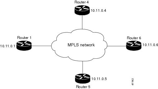
The configuration example shows the following:
- Targeted sessions between Routers 1 and 4 and Routers 1 and 5 use LDP. Routers 1, 4, and 5 are active.
- Targeted sessions between Routers 1 and 6 use LDP. Router 1 is active and Router 6 is passive.
By default, a router cannot be a passive neighbor in targeted sessions. Therefore, Router 1, Router 4, and Router 5 are active neighbors in any targeted sessions. The discovery targeted-hello accept command permits Router 6 to be a passive target in targeted sessions with Router 1. Router 6 can also be an active neighbor in targeted sessions, although the example does not include such a configuration.
Examples: Specifying the LDP Router ID
The following example shows how to assign interface Ethernet 2/2 as the LDP router ID:
The following example shows how to display the LDP router ID (10.15.15.15):
Examples: Preserving QoS Settings with an MPLS LDP Explicit-Null Label
The following example shows how to configure an explicit-null label on an egress LSR, which causes that LSR to advertise the explicit-null label to all adjacent MPLS routers:
The following example shows how to configure an explicit-null label and specify the for keyword with a prefix list, which causes all adjacent MPLS router tables to swap an explicit-null label only for those entries specified in the prefix list:
The following example shows how to configure an explicit-null label and specify the to keyword with a prefix list, which enables you to advertise explicit-null labels only to those adjacent routers specified in the prefix list. To advertise an explicit-null label to a particular router, you must specify the router’s LDP ID in the prefix list.
The following example shows how to configure an explicit-null label with both the for and to keywords, which enables you to specify which routes to advertise with explicit-null labels and to which adjacent routers to advertise these explicit-null labels:
Additional References for MPLS LDP
For additional information related to implementing MPLS LDP, see the following sections:
Related Documents
|
|
|
|---|---|
MIBs
|
|
|
|---|---|
Feature History for MPLS LDP
Table 3-2 lists the release history for this feature.
|
|
|
|
|---|---|---|
 Feedback