Cisco Nexus 5000 Series NX-OS FCoE Operations Guide, Release 5.1(3)N1(1)
Bias-Free Language
The documentation set for this product strives to use bias-free language. For the purposes of this documentation set, bias-free is defined as language that does not imply discrimination based on age, disability, gender, racial identity, ethnic identity, sexual orientation, socioeconomic status, and intersectionality. Exceptions may be present in the documentation due to language that is hardcoded in the user interfaces of the product software, language used based on RFP documentation, or language that is used by a referenced third-party product. Learn more about how Cisco is using Inclusive Language.
- Updated:
- August 15, 2013
Chapter: FcoE Port Configuration Examples
FCoE Port Configuration Examples
This appendix describes port configuration examples relating to FCoE topologies and it includes the following sections:
VE Port Configuration Example
This section provides a sample configuration of the Cisco Nexus 5000 Series switch FCoE VE Port implementation. The configuration covers the switches in switch mode. FCoE initiators are used in this lab. You can attach either FC F Port storage directly to a Nexus 5000 Series switch FC GEMs, or use an FCoE target.

Note![]() This example can be used for configuring VE ports between two Cisco Nexus 5000 Series switches in both fabrics. It does not include server configurations.
This example can be used for configuring VE ports between two Cisco Nexus 5000 Series switches in both fabrics. It does not include server configurations.
FCoE VE Port Topology Example
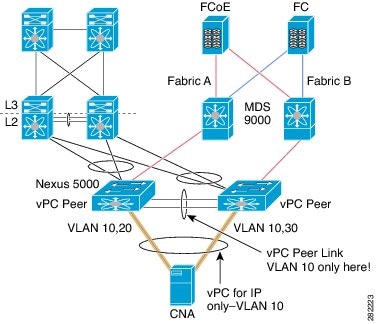
Figure 3-1 shows the topology that was used for the configuration example. The following configuration parameters are used in this topology:
- FCoE VLAN for Fabric A: 10
- FCoE VSAN for Fabric A: 10
- FCoE VLAN for Fabric B: 20
- FCoE VSAN for Fabric B: 20
- Ethernet Only VLAN across both fabrics: 200
You should choose these values before the time of configuration.
Figure 3-1 FCoE VE Port Topology
Note![]() The FCoE VLAN/VSAN numbering does not have to be the same within the fabric. As a best practice, use different FCoE VLANs and VSAN numbers between the two fabrics to avoid confusion. Configurations have often been set up to assign ODD VLAN/VSANs for one fabric and EVEN VLANs/VSANs for the other fabric. This is just one example of keeping the numbers separate between the two fabrics
The FCoE VLAN/VSAN numbering does not have to be the same within the fabric. As a best practice, use different FCoE VLANs and VSAN numbers between the two fabrics to avoid confusion. Configurations have often been set up to assign ODD VLAN/VSANs for one fabric and EVEN VLANs/VSANs for the other fabric. This is just one example of keeping the numbers separate between the two fabrics
Enabling FCoE and Verifying QoS Configuration
Step 2![]() (Optional) If you do not want to use the default Quality of Service (QoS) settings, specify your own policies:
(Optional) If you do not want to use the default Quality of Service (QoS) settings, specify your own policies:
Note![]() Note: if you use custom policies, class-fcoe must be included in your QoS policies.
Note: if you use custom policies, class-fcoe must be included in your QoS policies.
Step 3![]() Verify that the FCoE policy maps can be found in the running configuration:
Verify that the FCoE policy maps can be found in the running configuration:
Note![]() Note: If you specified customized QoS policy map names in Step 2, make sure you replace the default map names with your customized map names.
Note: If you specified customized QoS policy map names in Step 2, make sure you replace the default map names with your customized map names.
Quality of Service configuration on the Nexus 5000 series consists of three main constructs:
- Class-map and policy-map type qos: for classification purposes
- Class-map and policy-map type network: for network properties such as drop and no drop, queue size
- Class-map and policy-map type queueing: for bandwidth allocation
This exercise consists of changing the bandwidth allocation and the COS settings for FCoE.
Without proper configuration of class-fcoe in QoS, the following problems may occur:
- vFC interfaces do not come up (CNAs require advertisement of DCB parameters for FCoE)
- Drops noticed for I/Os
Note QoS has the following guidelines:
- A classification policy-map only applies in input
- A network policy-map applies globally (system)
- A queueing policy-map normally is meaningful in output, but since the exercise uses it to control the bandwidth allocation from CNA to the Cisco Nexus 5000 Series switch, in this case it is applied in input
Beginning in Cisco NX-OS Release 5.0(2)N1(1), you can modify the buffer allocation for no-drop classes:
Step 4![]() Verify the FCoE system class is active:
Verify the FCoE system class is active:
Step 5![]() Repeat Step 1 through Step 4 on both upstream Cisco Nexus 5000 Series switches (CORE_N5k-1 and CORE_N5k-2 in this example).
Repeat Step 1 through Step 4 on both upstream Cisco Nexus 5000 Series switches (CORE_N5k-1 and CORE_N5k-2 in this example).
Configuring VE Ports
FCoE VLAN and VSAN numbering in this example is as follows:
Note![]() There are two switches in Fabric A and two switches in Fabric B. The FCoE VLAN/VSANs must match between the switches in the same fabric in order to bring up the VE port between them.
There are two switches in Fabric A and two switches in Fabric B. The FCoE VLAN/VSANs must match between the switches in the same fabric in order to bring up the VE port between them.
Step 1![]() Configure the VSAN on the Nexus 5000 Series switch for Fabric A:
Configure the VSAN on the Nexus 5000 Series switch for Fabric A:
Step 2![]() Configure the FCoE VLAN to VSAN mapping and verify that it is up and operational for Fabric A:
Configure the FCoE VLAN to VSAN mapping and verify that it is up and operational for Fabric A:
Step 3![]() Repeat Step 1 and Step 2 on the upstream Nexus 5000 Series switch in Fabric A.
Repeat Step 1 and Step 2 on the upstream Nexus 5000 Series switch in Fabric A.
Step 4![]() Configure the VSAN on the Nexus 5000 for Fabric B:
Configure the VSAN on the Nexus 5000 for Fabric B:
Step 5![]() Configure the FCoE VLAN to VSAN mapping and verify that it is up and operational for Fabric B
Configure the FCoE VLAN to VSAN mapping and verify that it is up and operational for Fabric B
Step 6![]() Repeated Step 1 and Step 2 on the upstream Nexus 5000 Series switch in Fabric B.
Repeated Step 1 and Step 2 on the upstream Nexus 5000 Series switch in Fabric B.
Step 7![]() Configure the underlying 10-Gigabit Ethernet port that the vFC interface will be bound to. The VE port will use this interface as the physical transport for FCoE traffic between the two switches. This interface needs to be configured to trunk the appropriate FCoE VLAN as well as the Ethernet VLAN (in this example, we are using VLAN 200 to carry Ethernet traffic).
Configure the underlying 10-Gigabit Ethernet port that the vFC interface will be bound to. The VE port will use this interface as the physical transport for FCoE traffic between the two switches. This interface needs to be configured to trunk the appropriate FCoE VLAN as well as the Ethernet VLAN (in this example, we are using VLAN 200 to carry Ethernet traffic).
The 10-Gigabit Ethernet interfaces connecting the switches in this lab are shown in the topology above:
- Fabric A uses FCoE VLAN 10 and VSAN 10
- Fabric B uses FCoE VLAN 20 and VSAN 20
- PODX-N5K-1 (Fabric A) uses Ethernet 1/15 to connect to CORE N5K1
- PODX-N5K-2 (Fabric B) uses Ethernet 1/16 to connect to CORE N5K2
Configuration for both switches in Fabric A:
Configuration for both switches in Fabric A:
Step 8![]() Configure the vFC interface on the switch that will be bound to the VE port and add this vFC interface to VSAN 44 in the VSAN database:
Configure the vFC interface on the switch that will be bound to the VE port and add this vFC interface to VSAN 44 in the VSAN database:
The vFC numbers for the VE ports are as follows:
- Fabric A uses FCoE VLAN 10 and VSAN 10
- Fabric B uses FCoE VLAN 20 and VSAN 20
- POD1-N5K-1 (Fabric A) uses Ethernet 1/15 to connect to CORE N5K1
- POD1-N5K-2 (Fabric B) uses Ethernet 1/16 to connect to CORE N5K2
- POD1-N5K-1 (Fabric A) uses vfc 15 and binds it to Ethernet 1/15
- POD1-N5K-2 (Fabric B) uses vfc 16 and binds it to Ethernet 1/16
Configuration for both switches in Fabric A:
Configuration for both switches in Fabric B:
Note![]() Don’t forget that these interface configurations must be configured on both sides of the ISL connecting the two switches in the same fabric.
Don’t forget that these interface configurations must be configured on both sides of the ISL connecting the two switches in the same fabric.
Step 9![]() Verify that the vFC is up and operational. By default, the vFC will show as trunking. Make sure that it is bound to the correct physical interface and that VSAN 44 shows as allowed and active as well as up on the vFC interface.
Verify that the vFC is up and operational. By default, the vFC will show as trunking. Make sure that it is bound to the correct physical interface and that VSAN 44 shows as allowed and active as well as up on the vFC interface.
Verify both switches in Fabric A:
Verify both switches in Fabric A:
 Feedback